Mainshaft Assembly How to Assemble the Mainshaft Assembly Special Instructions Each mainshaft gear must have its I.D. snap ring installed before placement on the mainshaft. Do not replace reverse gear I.D. snap ring. Gear limit washers are internally splined and locked to the mainshaft by the key. Gear spacers are externally splined to engage with gear hub clutching teeth. There is one limit washer and one spacer for each mainshaft gear. Axial clearance (end-play) limits are .006"-.015" for all mainshaft gears. If the axial clearance is less than the minimum .006" tolerance, the limit washer should be replaced with a thinner limit washer. This will increase the axial clearance between the gears. If the axial clearance is greater than the maximum .015" tolerance, a thicker limit washer should be installed. This will decrease the axial clearance between the gears.
Special Tools •
A vise with brass jaws or wood blocks
•
Feeler gauges
•
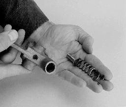
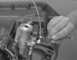
A piece of 5/32" air line, 1' long
Procedure -
119
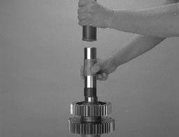
1.
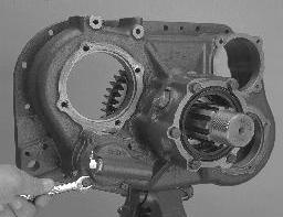
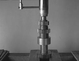
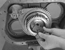
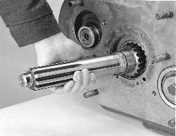
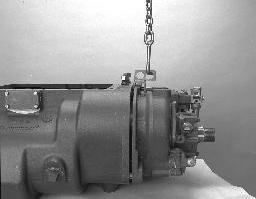
With mainshaft pilot-end down, secure the mainshaft in a vise equipped with brass jaws or wood blocks.
2.
If previously removed, install the roll pin in keyway.
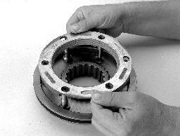
3.
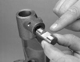
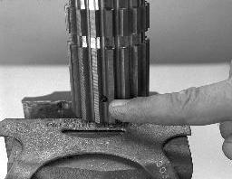
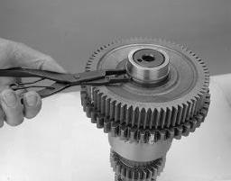
With the washer flat side up, position the 3rd speed gear limit washer (white) in the mainshaft 1st or bottom groove. Rotate the washer until the washer splines and mainshaft spIines align.
4.
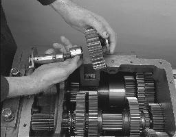
Start at the mainshaft bottom and install the air line in the keyway to lock the washer in place. As limit washers and gears are installed, continue to push the air line up.