2 minute read
Timing Procedures

It is essential that both countershaft assemblies of the front and auxiliary sections are "timed." This assures proper tooth contact is made between mainshaft gears seeking to center on the mainshaft during torque transfer and mating countershaft gears that distribute the load evenly. If not properly timed, serious damage to the transmission is likely to result from unequal tooth contact causing the mainshaft gears to climb out of equilibrium.
Timing is a simply procedure of marking the appropriate teeth of a gear set prior to installation and placing them in proper mesh while in the transmission. In the front section, it is necessary to time only the drive gear set. And depending on the model, only the LO range, deep reduction, or splitter gear set is timed in the auxiliary section.
Front Section
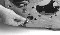
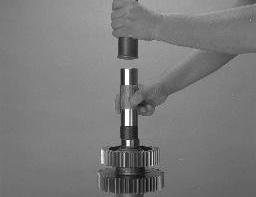
A. Marking countershaft drive teeth.
1. Prior to placing each countershaft assembly into the case, clearly mark the tooth located directly over the drive gear keyway as shown. This tooth is stamped with an "O" to aid identification.
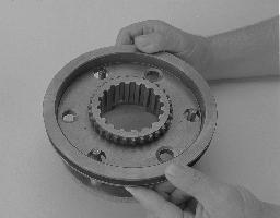
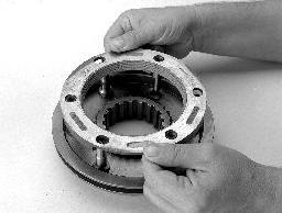
B. Marking main drive gear teeth.
1. Mark any two adjacent teeth on the main drive gear. 2. Mark the two adjacent teeth located directly opposite the first set marked on the main drive gear. As shown to the left, there should be an equal number of unmarked gear teeth on each side between the marked sets.
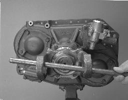
C. Meshing marked countershaft drive gear teeth with marked main drive gear teeth.
(After placing the mainshaft assembly into the case, the countershaft bearings are installed to complete installation of the countershaft assemblies.) 1. When installing the bearings on the left countershaft, mesh the countershaft drive gear marked tooth with either set of main drive gear two marked teeth. 2. Repeat the procedure when installing the bearings on the right countershaft, make use of the remaining set of main drive gear two marked teeth to time assembly.
Auxiliary Section
A. Timing the auxiliary countershafts.
Standard Auxiliary Section 1. Mark any two teeth on the LO range gear. Then mark two teeth located directly opposite the first marked. 2. Prior to placing each auxiliary countershaft assembly into housing, mark the tooth on each auxiliary countershaft assembly LO range gear stamped with the "O". 3. Follow the assembly procedures in the "Auxiliary Section".
Helical Auxiliary Section 1. Mark any tooth on the LO range gear. Then mark a tooth located directly opposite the first marked. 2. Prior to placing each auxiliary countershaft assembly into housing, mark the two teeth on each auxiliary countershaft assembly LO range gear stamped with the two "O"s. Repeat the procedure on each auxiliary countershaft reduction gear. 3. Follow the assembly procedures in the "Auxiliary Section".