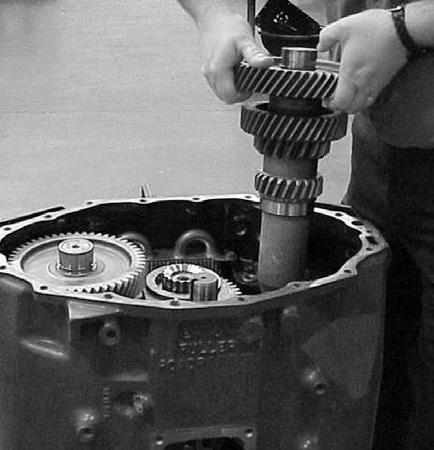
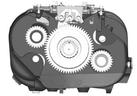
Timing Timing Procedures Special Instructions Both front and rear countershaft assemblies must be "timed". Correct timing assures the mainshaft gears will be properly centered between the countershafts. Timing is a simple service procedure completed by marking the appropriate teeth of a gear set prior to installation and placing them in proper mesh during assembly. Since Lightning models are assembled as a single unit, there are three critical gear sets that must be timed. In the order in which they are assembled, these gears include: the splitter gear set, the auxiliary mainshaft drive gear set, and the 3rd/4th gear set.
Special Tools •
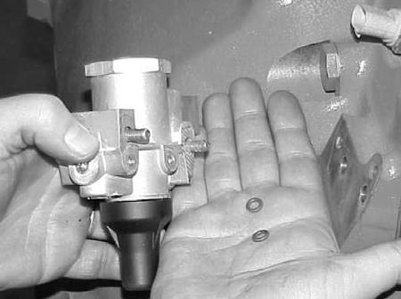
Tool Markers Dye
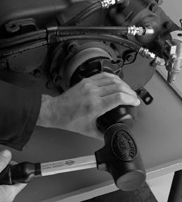
Procedure 1.
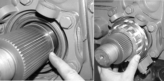
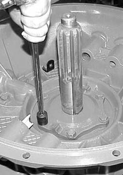
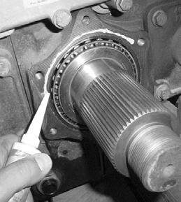
Marking the auxiliary mainshaft splitter gear
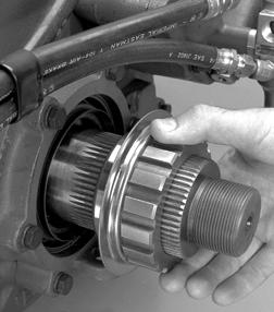
2.
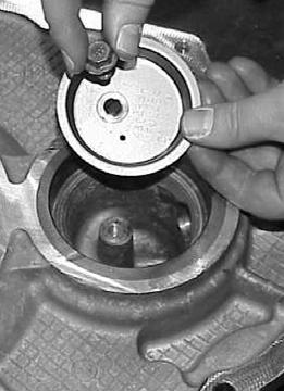
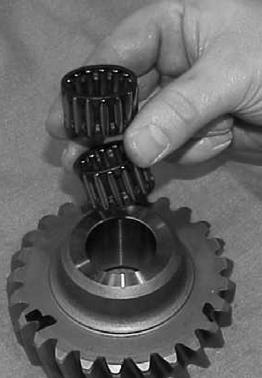
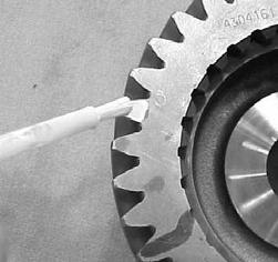
Prior to installing the splitter gear on the end of the auxiliary mainshaft, clearly mark any two teeth that are directly opposite of each other. Mark the teeth on the front side of the gear identified by the internal clutching teeth.
3.
There should be an equal number of unmarked gear teeth between the marked teeth.
1.
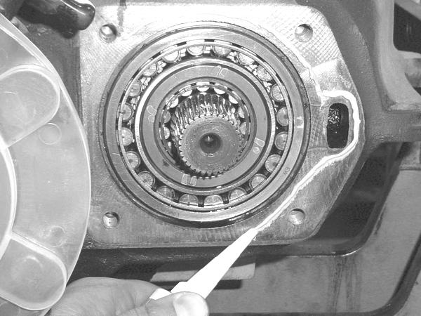
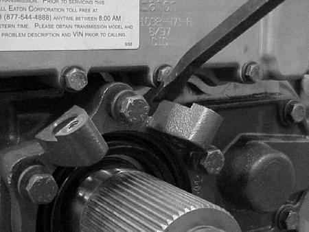
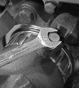
Marking the auxiliary countershaft gears
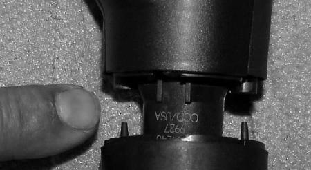
2.
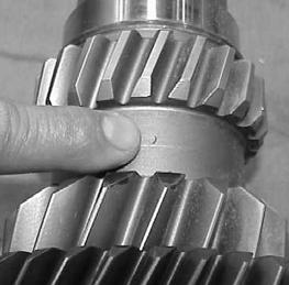
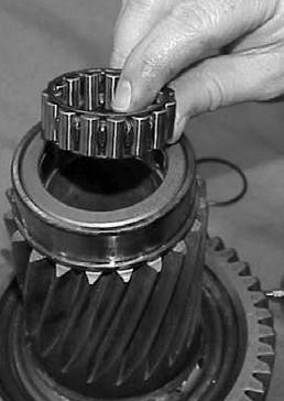
Locate the timing mark on the rear side of the forward most gear (auxiliary coutershaft driven gear) and mark the two adjacent teeth next to the timing mark as shown.
3.
Repeat the procedure for the two teeth on the next gear (auxiliary countershaft splitter gear) that line up exactly with the timing mark on the drive gear.
28
Timing
Since Lightning transmission models contain all helical style gearing and the countershafts are single piece units, the process of marking the gear teeth is unique compared to other models.