


01 | 2023 EMO - Journal Anzeige the machine
Hall 9, E24 e.g. cobot for only €4,970
tool industry: REMOLDING

Innovative 3-D printing, interlinked production processes, man-machine-collaboration and sustainability. As the world´s leading trade fair for the manufacturing industry, EMO Hannover focuses on current topics in production technology and at the same time builds bridges to business models of the future.


With the only official trade fair magazine, VDI nachrichten and VDI Fachmedien inform trade fair visitors about exhibitors and products, showcase technical world novelties and let experts from science and industry have their say.

Von Jens D. Billerbeck Jean-Marc Chery, STMicroelectronics, Reinhard Ploss, Infineon, und Kurt Sievers, NXP. Ihnen zur Seite der ZVEI-Präsident und Chef von Pepperl & Fuchs, Gunther Kegel. Letzterer brachte die Stimmung der Branche auf den Punkt: „Wir wurden ins kalte Wasser geworfen, aber wir haben schnell gelernt zu schwimmen.“
Einhellig waren die CEOs im Panel der Meinung, die Corona-Pandemie habe im Frühjahr zu starken Verwerfungen und unklarer Risikolage bezüglich der weltweiten Lieferketten der Chipindustrie geführt, doch mittlerweile sei man unter veränderten Bedingungen wieder auf der Erfolgsspur. Einige Branchen hätten sich gerade wegen der Pandemie erfreulich entwickelt, so der Bereich IT und Kommunikation. Egal, ob der Markt nun 2021 oder erst 2022 die Ver-
luste des ersten Halbjahres 2020 kompensiert, an den langfristig positiven Aussichten für die Chipmärkte ließ keiner der Beteiligten Zweifel. Anhaltende Risiken wie die schwelenden Handelskonflikte und die Gefahr einer „entglobalisierten“ Welt schienen da deutlich präsenter als das Virus. Pragmatismus und die Fähigkeit, sich an neue Gegebenheiten schnell anzupassen, zeichnen die Industrie seit ihren Anfängen aus. Waren die
AD CLOSING DATE: 01-09-2023
PUBLICATION DATE: September 18, 20, 22
Bi-lingual German/English
Distributed directly to target group: As the only official trade fair magazine exclusively on the exhibition grounds to visitors as well as exhibitors. Motif change possible!!
Megathemen der vergangenen Jahre das Smartphone und die Cloud, setzt NXP-Chef Sievers für die nächsten zehn Jahre auf sicheres Edge-Computing: Datenverarbeitung inklusive künstlicher Intelligenz
Petra Seelmann-Maedchen Head of Sales Solutions


Phone: +49 211 6188-191
pmaedchen@vdi-nachrichten.com


Sarah Simon Head of Media Sales Phone: +49 211 6103-166 ssimon@vdi-fachmedien.de
Edition 60,000 Copies (3 daily issues)

In September it will be happening. After four years, EMO Hannover will take place again from 18 to 23 September 2023. Currently, around 1750 exhibitors from 42 countries are expected, representing the entire spectrum of production technology. According to the VDW (German Machine Tool Builders‘ Association) as organiser, EMO Hannover 2023 will focus on three megatrends: The Future of Business, The Future of Connectivity and The Future of Sustainability. This is a continuation from previous events. There, too, topics such as digitalisation or connectivity were the focus of the trade fair. So nothing new under the sun?
Thematically that may be true, but not in terms of content. For example, umati, the global initiative for open communication interfaces for the machine industry, will be even more extensively and comprehensively represented in Hannover. Meet-the-experts rounds and live demonstrations will show visitors the sophistication of the technical solutions and the benefits they can offer users. In the immediate vicinity in Hall 9, visitors will find the booths of the OPC Foundation and the Machine Information Interoperability (MII) department of the VDMA.
In our article „Smooth data flow“ starting on page 43, you can read how the „OPC UA Geometrical Measurement Systems“ working group has now succeeded in taking an important step towards standardising communication. The OPC UA Companion Specification for Geometric Measurement Systems (GMS) has been completed and adopted. According to the authors, the companies involved in the VDMA have completed the development of the interface in a record-breaking time. In addition, the working group „OPC UA Cutting Tools“ has been set up. The goal: the effective exchange of tool data between CAD/CAM system, tool grinding machine and measuring machine.
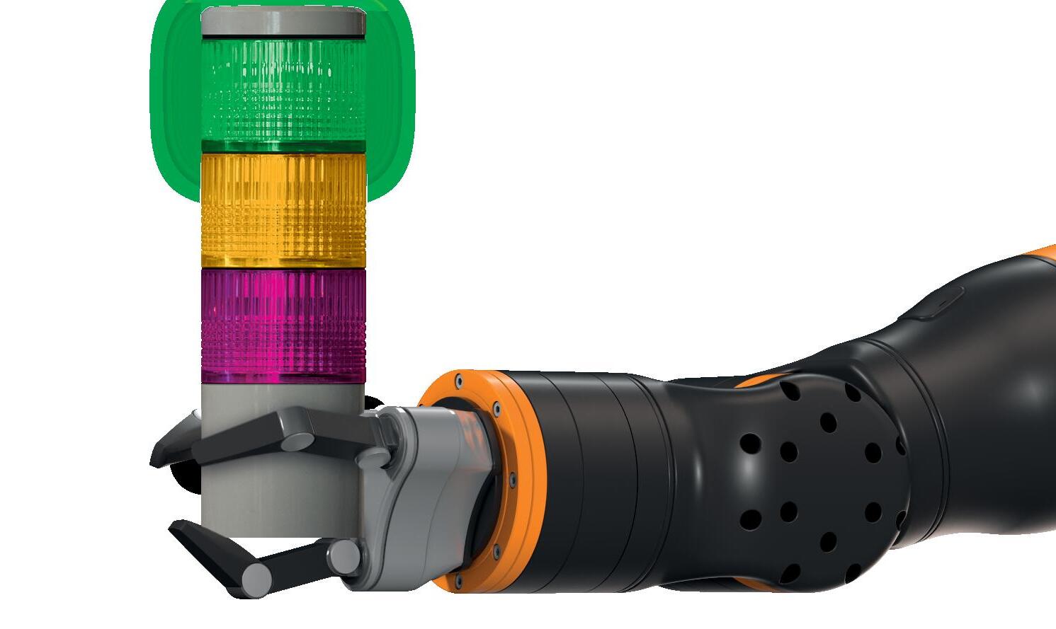
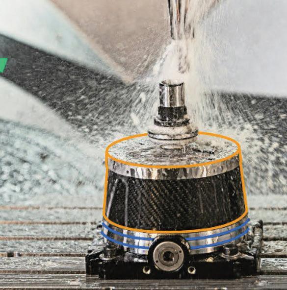
The topic of sustainability is also not really new, but it is becoming more and more concrete in its implementation. The tool manufacturer Ceratizit, for example, wants to demonstrate that high performance and particularly sustainable production are not mutually exclusive in high-performance tools. The company manufactures the geometry of a solid carbide milling cutter series from a specially developed carbide grade and can thus point to an extremely low carbon footprint.
Another example is the energy chain manufacturer igus, which has developed a process to recycle decommissioned energy chains, regardless of the original manufacturer. Since the start of the project, igus says it has already collected over 60 tonnes of high-performance plastics, half of which were collected last year. New products are created again from the recyclate, for example the first energy chain made from 100 percent recycled material.
Digitalisation and automation are, of course, still among the top topics in the industry. Not only because the technical solutions have developed significantly since the last EMO Hannover. The shortage of skilled workers has taken on a momentum that leaves companies no choice but to optimise processes and automate procedures and work steps. Artificial intelligence has come into play as another tool. Popularised by ChatGPT, AI is now on everyone‘s lips. In industry, AI is usually still called machine learning. But even there, development is progressing very quickly. With the technique of federated learning, for example, it is possible to train a common AI model with decentrally stored data without directly trading the data. This makes it possible to develop AI models even for companies that do not have enough data on their own to create a precise model.
The challenges to production technology are becoming more exacting and the industry is responding: in part with optimised, in part with completely new approaches to solutions. At EMO Hannover, all developments will be on show live. In this journal we present you with an excerpt, more information will follow: online at www.vdi-nachrichten.com, but also daily updated during the fair in the fair newspaper EMO Daily direct from the fairground!
Udo Schnell Editor-in-Chief Design/Editorial Director VDI Fachmedien
„The challenges are becoming more exacting and the industry is responding: in some cases with completely new approaches to solutions.“
EMO Hannover: joint booths make trend themes even more visible. The Sustainability in Production Area is attracting great interest because exhibitors are repositioning themselves in this field. Photo: VDW
p3 Meeting place for production technology
EMO Hannover
p6 Digitalisation and sustainability in the focus for industrial production
p9 umati back at EMO Hannover
p10 Artificial intelligence makes factories clever
p12 Start-ups pave the way to new businesses
p15 Online-capable chatter early warning system
p18 Silent Tools expand turn-drill-mill centres
p20 Spark erosion: efficiency through cleanliness
Start-ups: AR can be used to train new employees without interrupting production. Service technicians can also be guided remotely.

Software and automation
p22 Matrix production systems are flexible and productive
p24 Big Data leads to new business models
p28 A shortcut to the finished component
p30 The perfect tool for everyone
p33 Smart toolholder as data supplier
p36 Grooving with indexable inserts
p39 Stable processes through milling tool modification
p42 The search for the optimum tool
p43 Smooth data flow
p46 Efficient tool repair
p48 Automation from machine to process
E-Mobility
p51 How does manufacturing technology advance e-mobility?
p54 Spindle bearings for machine tools

p56 AM: High relevance of feedstock characterisation
p59 3D-printed tools: „on a par with the steam engine“
Tools: Intelligent tool holders require hardly more installation space than a conventional type and are in equal measure universally applicable and easy to integrate. Photo:


The retrofit solution for all existing lathes is now available. No integration into the machine control necessary!
More safety during machining
Impressum
Editorial Board:
Editor-in-chief Ken Fouhy, B.Eng. (kf)
VDI news
Dipl.-Kfm. Stefan Asche (sta), VDI trade media
Dr.-Ing. Birgit Etmanski (be)
Udo Schnell (us)
Editorial assistance: Alexandra Briesch
Editorial address: VDI-Platz 1, 40468 Düsseldorf, Germany
Telephone: +49 2 11 61 88–335
www.vdi-nachrichten.com

www.vdi-fachmedien.com
redaktion@vdi-nachrichten.com
Publisher:
VDI Verlag GmbH, VDI Fachmedien GmbH & Co. KG
VDI-Platz 1, 40468 Düsseldorf, Germany
PO Box 10 10 54, 40001 Düsseldorf
Telephone: +49 2 11 61 88–0
Commerzbank AG, BIC: DRES DE FF 300

IBAN: DE59 3008 0000 0214 0020 00
Executive management: Ken Fouhy, B.Eng.
Layout/Production: Gudrun Schmidt (responsible), Alexander Reiß
Advertisements: Petra Seelmann-Maedchen pmaedchen@vdi-nachrichten.com
Phone: +49 2 11 61 88–191
Sarah-Madeleine Simon ssimon@vdi-fachmedien.de
Phone: +49 (0) 211/6103–166
Disposition: Ulrike Artz (responsible), abwicklung@vdi-nachrichten.com
Telephone: +49 2 11 61 88–461
Sales management: Ulrike Gläsle
The publisher is not liable for unsolicited manuscripts, documents and pictures. The publication of stock exchange prices and other data is without guarantee.
Printing: KLIEMO AG, Hütte 53, 4700 Eupen, Belgium
-16 500
More information: roehm.biz/ijaw
Higher productivity
The slogan of this year‘s EMO Hannover is „Innovative Manufacturing“. Because production technology is not an insider event, the organiser emphasises; industry is making an important contribution to solving the pressing problems of our time – with innovative business models, the networking of people, machines and the Internet of Things, and also the sustainability of production technology. These mega-topics are the focus of the trade fair from 18 to 23 September in Hannover.

More than 1,750 exhibitors from 42 countries are currently expected at EMO Hannover 2023. They will present the entire spectrum of production technology from 18 to 23 September. Key areas include machining centres and lathes, cutting tools and clamping devices, measuring equipment and control systems. „The breadth of the technical range is unparalleled at international trade fairs for production technology,“ says Dr. Markus Heering, Managing Director of the VDW (German Machine Tool Builders‘ Association). It shows, he says, what the challenges in production are: higher efficiency, more flexibility, better quality, greater precision, the integration of AI, comprehensive networking in the factory and much more.
At the beginning of July, the VDW, in its capacity as EMO Hannover organiser, had invited visitors to Frankfurt am Main for the big preview. A good ten weeks before the major event, 31 exhibitors at the EMO Hannover will be offering a glimpse behind the scenes of their new products.
„The EMO Hannover Preview is taking place in Frankfurt am Main for the first time. The event has a long tradition and is the highlight and conclusion of our EMO Hannover World Tour. Since the beginning of the year, we have presented the EMO Hannover 2023 to the EMO community at around 60 events in 40 countries from Japan to Mexico and from Finland to South Africa“, said Dr. Wilfried Schäfer, Managing Director at the VDW, welcoming the guests.
Markus Heering: „Under the slogan Innovate Manufacturing we have focused on three megatopics for this year‘s EMO Hannover:


• The Future of Business,
• The Future of Connectivity and
• The Future of Sustainability in Production.
They are intended to show that production technology is not an insider event for experts, but that industry is making its contribution to solving the pressing problems of our time. And this is what
Joint booths:
• Additive Manufacturing
• Connectivity
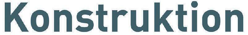
• Cobots
• Sustainability in Production
Special booths:
• Education
• umati Forums (Halls 9 and 16):
• Business opportunities in the Indian market
• New Digital Work – opportunity or disenfranchisement?
• umati
• Energy efficiency through digitalisation
• E-mobility
• Climate-neutral production
• Potential of circular business models
• Best practices (sustainability) www.emo-hannover.de (all data: status July 2023)
the exhibitors show with their technical solutions here at the Preview and in September at the fair in an impressive variety and depth.“
To make trend themes even more visible, EMO Hannover offers various joint booths: Additive Manufacturing, Connectivity, Cobots and Sustainability in Production. „In particular, information opportunities on new topics, such as the Sustainability in Production Area, are
attracting great interest because exhibitors want to reposition themselves in this field,“ reports Wilfried Schäfer. The booth is also used by research institutes, which present their sustainability projects there.
As the world‘s leading trade fair for production technology, the EMO Hannover aims to address all important topics relating to the industrial value chain, to present state-of-the-art developments and to show scenarios for future development.
„In addition to the aforementioned topics, the focus will be on recruiting skilled workers at the special Education booth, among other things. The range of services
offered by the Foundation for Young Mechanical Engineers has been extended beyond vocational training to include advanced training,“ Markus Heering explains. The special umati stand will show the current status of the connectivity initiative of the mechanical and plant engineering industry as the basis for efficient networking in the factory with a large live demonstration. Finally, the Startup Area promotes forward-looking cooperation with young companies, says Schäfer, describing two further examples.
The joint booths are complemented by two forums in Hall 9 and Hall 16 of the Hannover Exhibition Centre. They offer space for exhibitors‘ presentations on technology topics and for in-depth presentations of special topics that are discussed in the context of Future Insights. The programme currently includes a conference on business opportunities in the Indian market and two halfdays entitled „New Digital Work – Opportunity or Disenfranchisement?“ Both will delve into individual aspects of the Future of Business. Further half-days on the topics of umati and energy efficiency
through digitalisation represent the Future of Connectivity. Finally, lectures and discussions on e-mobility, climate-neutral production, potentials of circular business models and best practices with regard to sustainability in production will pick up aspects of Sustainability in Production.
The lectures are closely linked to EMO Hannover digital, which has already been launched in the run-up to the fair. „Some of the lectures, conferences and thematic focal points will be streamed live or recorded and will be available on demand via our website www.emo-hannover.de, as will this preview, by the way. In this way, we want to give our exhibitors greater reach and not deprive visitors who may not be able to take advantage of all the offers of in-depth information and discussions“, explains Wilfried Schäfer from the VDW.
The above-mentioned forums and events not only offer in-depth information, but also promote exchange and discussion among participants. After all, as the world‘s leading trade fair for production technology, the EMO Hannover is better suited than any other trade fair to expanding the international network

with manufacturing experts on the supplier and customer side, as well as from the scientific community.
EMO Hannover digital is already contributing to this with EMO sessions, digital chats and video meetings in the runup, even across geographical borders. In addition, all visitors will receive a matchmaking offer when they register online at www.emo-hannover.de in the ticket shop. There they can deposit their profile and interests and arrange appointments with like-minded people after the match.
„After a four-year break, EMO is returning to Hannover – with a new concept, a new look and a fresh impetus,“ concludes Wilfried Schäfer. „The mood is good. The preview has shown that. Our exhibitors and we as organisers are very much looking forward to seeing our customers and business partners again.“


At EMO Hannover 2023, it can be said that umati is back – bigger and more comprehensive than ever before. The community of now more than 300 umati partners will be demonstrating live in Hannover how easily decentralised communication between machines, components and software works – going far beyond the machine tool.


umati (universal machine technology interface) is the global initiative for open communication interfaces for the machine industry and its customers. Machine builders, software manufacturers, component suppliers and users are joining together to form a strong community to promote the use of open, standardised interfaces based on OPC UA Companion Specifications. umati ensures their identical implementation, provides a platform for sharing experience, creates visibility in the market and demonstrates the added value in a practical way.

There are now over 300 umati partners involved in the umati community. More than half of these partners are currently companies or institutions outside of Germany, and 80 % of the partners are companies. This makes umati truly a global initiative by companies for companies, and the only standard that provides a live demonstration of concrete data exchange in a shared, globally available data ecosystem.
The central point of contact at EMO Hannover will be the umati exhibition stand in Hall 9, F24. Meet-the-experts sessions will be held several times a day. Interested parties can obtain first-hand information from the umati team and representatives of umati partner companies about the background, technology and benefits of open, standardised data interfaces for mechanical engineering. With the help of various exhibits, they can also directly appreciate how mature the technical solutions have in the meantime become. In the immediate vicinity are the booths of the OPC Foundation and the Machine Information Interoperability (MII) department of the VDMA. This represents the strong trio of OPC UA as the basic technology, the Global Production Language promoted by the VDMA in the form of OPC UA Companion Specifications for the numerous technologies of machine and plant construction, and umati for implementation and marketing.
However, the actual framework for the live demonstration will be created by the numerous exhibiting partner companies participating with their machines, components and software solutions. For EMO Hannover, these include not only manufacturers of machine tools but also suppliers of geometric measuring technology, additive manufacturing, robotics, image processing and, of course, software manufacturers. Via a QR code on each device that is connected to the umati demonstrator, all visitors can see for themselves how its data flows directly into the demonstrator application umati.app. There they are displayed in a uniform format with data from other devices and are thus available to the user. Software providers will also be able to integrate themselves into this data flow and demonstrate the benefits of their products directly and live, based on real data from the machine pool at EMO Hannover.
 Dr. Alexander Broos Head of Research and Technology at the VDW Managing Director VDW Research Institute Tel.
+49 69 756081-17


a.broos@vdw.de www.emo-hannover.de


• Several times a day: Meet the experts
• Exhibits at the booth
• Live demonstrations at the booth
• Hall 9, Booth F 24
Since the triumph of the chatbot ChatGPT, artificial intelligence (AI) has been on everyone‘s lips. AI is also making great strides in industrial production technology. Machine learning is making production more efficient. How does this work exactly? Interested parties can find out at EMO Hannover 2023.
Can production machines optimise themselves under their own steam? Can they learn from their mistakes? And can they acquire know-how from other machines? With artificial intelligence (AI), all this is possible. „We have worked for a long time on optimising our processes in production technology and have achieved a competitive
advantage here, one we should now also achieve in the digital transformation of industrial production,“ explains Markus Spiekermann, Head of Department Data Management at the Fraunhofer Institute for Software and Systems Engineering ISST. To meet the new requirements, AI plays a „decisive role“, says Spiekermann. „For only by using AI methods can a high degree of automation be achieved.“
The trend towards AI has arrived in industry. The machine tool manufacturer J.G. Weisser Söhne GmbH & Co. KG, for example, relies on AI models that enable predictive maintenance of lathes.
„Predictive maintenance uses AI to forecast when a machine will need maintenance before it breaks down,“ explains Dr.-Ing. Robin Hirt, CEO and founder of the Karlsruhe-based start-up Prenode GmbH.

Modern production machines can optimise themselves with the help of AI, says Hirt. „They usually use so-called machine learning methods to do this, which enable them to recognise patterns and correlations in the production data and automatically derive improvements from them.“ Learning from mistakes and adopting know-how from other machines is also possible in many cases this way, he adds.
Because the data from a single lathe is often not sufficient to train a precise AI model, the technique of federated learning is used. Federated learning makes it possible to train a common AI model with decentrally stored data without directly exchanging the data. The individual data therefore remain on the respective machines and do not have to be stored centrally in one place, for example in the machine manufacturer‘s cloud.
The AI models estimate the current status of the system based on current lathe data and pass this on to the operating personnel. Neural networks from the field of deep learning are used for this.
Artificial intelligence is also used in the Sorting Guide, a system from the laser specialist Trumpf in Ditzingen, BadenWürttemberg, which helps sort produced parts and can thus increase machine utilisation. The Sorting Guide is a camerabased assistance system and relies on


decentralised machine learning. The main components of the AI system are a highresolution camera, a large screen, an industrial PC and intelligent software for image processing.
„With decentralised machine learning, several machines are networked with each other and together form an AI system,“ Prenode managing director Hirt explains the principle. In the process, the machines continuously collect local data about their work processes. Then an AI model is developed for each machine, which is then centralised. „In a central cloud, these models are then merged and transferred back to the individual machines,“ Hirt continues. The AI system can then access all the experience of the other machines locally without ever having to exchange sensitive raw data. „In this way, the machines can organise their operations more efficiently and achieve higher productivity,“ Hirt promises.
Trumpf‘s Sorting Guide recognises output parts through existing master data and self-learning image processing and makes a sorting recommendation via the screen. Because the produced parts are marked in colour on the screen, the machine operators can see at a glance which parts are ready for further processing and where, if necessary, post-production must be initiated.
A new method that analyses tool wear in machining processes, such as drilling or milling, also relies on artificial intelligence. On the one hand, the expensive tools should be used as long as possible. On the other hand, it is important to accurately estimate the remaining service life. In order to reliably predict the state of wear and thus optimise cutting processes, researchers at the Technical University of Kaiserslautern have developed a procedure that trains the system using real process and measurement data.
The data that the system needs for learning are collected from five partner companies – among them are global players as well as small and medium-sized enterprises. In the process, different variants are run through, for example with regard to tool and material types or process parameters, and thus a broad database is collected over the entire service life up to the failure of the tool.
Never ceasing in their commitment to creating the highest quality product, years of continuous refinements at ANCA have made the ULTRA technology possible. ANCA’s unique vertical integration is key to its success - where machines, controls, drives and precision components are all designed and manufactured in-house. Successfully introduced to the industry last year on the MX machine platform, it boasts the highest accuracy and quality cutting tools in the world. In fact, the MX7 ULTRA achieves one nanometre axis resolution, and can maintain less better than +/- 0.002mm line form accuracy of any profile which includes ballnose and corner radius endmills. At EMO, visitors will find out how ANCA spreads the ULTRA advantages to further fields of application, including smaller batches, regrinding and tools with small diameters.
Scan to learn more

Established machine builders cooperate with young companies
Gripping systems modelled on gecko feet, VR goggles for employee training, cloud platforms for fast ordering of CNC components: Ideas from founders help big companies optimise their processes and tap new sources of revenue.

Saturday morning, early shift in the production plant of an automotive supplier. The hectic pace is palpable when suddenly the CNC milling machine goes on strike. Every minute that the machine is at a standstill causes financial loss for the company. The annoyance grows when the technician has to fight his way through heavy rush-hour traffic to get to
the site. A situation that the competing company from the neighbouring town does not have to fear. Here, the technician uses the advantages of Industry 4.0: he accesses the CNC milling machine via the internet and identifies the source of the error. After only five minutes, the system shutdown is over.
This rapid response is possible because the machine manufacturer recognised the signs of the times and jumped on the
digitalisation bandwagon at an early stage. It equipped the machine with sensors and integrated it into the cloud. In cooperation with a start-up that specialises in sensor technology and Industry 4.0.
This is a path that more and more machine builders are taking in order to become the shapers of disruptive changes in the market. A member survey by the German Engineering Federation (VDMA) shows that 81 % of mechanical enginee-
ring companies now use networking platforms to identify partners from the startup scene. Through these collaborations, the often long-established companies gain access to new technologies and process knowledge. They lay the foundation for developing new products and business models beyond the classic core business.
Start-ups that are familiar with the technology topics of the future – such as the Industrial Internet of Things (IIoT), cloud-based services, data analytics and artificial intelligence – are particularly sought after.

Machine tool manufacturer Trumpf also relies on cooperation with start-ups. „As a high-tech company, we not only have to pick up on the trends of the times, but ideally anticipate them,“ says Niklas Hering, investment manager at Trumpf Venture GmbH. „In this context, close cooperation with start-ups forms an important building block in Trumpf‘s innovation concept and optimally complements our tradition of internal innovation.“
One example of such collaboration is the cooperation with ScaleNC, a young company that has developed a platformbased service package for sheet metal processors. The service works as follows: Customers can upload drawings, sketches and computer aided design (CAD) models of parts to be manufactured to a cloud platform. Computer Aided Manufacturing (CAM) experts then remotely take over the programming of all common Trumpf machines for sheet metal processing, supported by algorithms. This makes it possible to create even demanding CNC programmes in a short time.
„ScaleNC is the answer to the shortage of skilled workers. Many of our customers have difficulty filling vacancies,“ says Tom Schneider, Managing Director Research & Development at Trumpf Werkzeugmaschinen. „In addition, ScaleNC provides cost advantages and helps our customers strengthen their competitive position.“ It is a service that is finding favour around the world. „The need for cloud-based services is growing in the industry and we look forward to making our solutions available to even
more customers,“ says Holger Röder, founder and CEO of ScaleNC. The startup is currently preparing to enter the US market.
Festo AG, a manufacturer of control and automation technology from Esslingen am Neckar, also knows how important start-ups are for the future of machine builders. „Start-ups are also taking on an increasingly important role in the field of mechanical and plant engineering, especially for medium-sized companies,“ says Jochen Schließer, Head of Innovation Projects and Networks at Festo. „Good scouting on defined topics is the first step towards cooperation.“ Since 2014, the company has been working with start-ups to make its own processes more efficient.
One example is the cooperation with Holo-Light, a German-Austrian tech startup from Innsbruck that specialises in Industry 4.0 solutions with augmented reality (AR) devices. These include the Microsoft Holo-Lens, AR glasses that add digital content to the user‘s vision. This makes it possible, for example, for a technician to draw repair or assembly instructions remotely in real time in the field of vision of the person wearing the glasses. Holo-Light was able to demonstrate the other advantages of this augmented reality in a pilot project at Festo‘s plant in Rohrbach. Normally, employees there learn
how to handle technology on the machines in the factory itself. The disadvantage: during this time, the machines cannot produce. The alternative: data glasses that use holographic images and voice instructions to guide employees step by step through operating processes in a training room. This way, the new employees can learn assembly processes and safety rules virtually. Without interrupting the production flow.
Among the young companies in the field of mechanical engineering is Spanflug Technologies GmbH, a Munich startup, spun off from the Institute for Machine Tools and Industrial Management (IWB) at Munich Technical University (TUM). The founders are addressing the following problem: when companies want to commission a CNC-manufactured component, they often find themselves sweating. Especially with complex geometries, the calculation for turned and milled parts is complicated and requires a lot of time and expertise. So does the search for a supplier who has sufficient capacity. Thus, according to Spanflug, the conventional procurement process causes costs amounting to 20 % of the component costs on average. The founders have therefore set themselves the goal of automating the parts procurement process in the manufacturing industry.
To this end, the start-up has launched an online platform that has already been joined by over 200 CNC manufacturing partners from Germany and Austria. More than 3000 customers are already using the platform to procure turned and milled parts. They can upload information about the desired components there. „Our software automatically calculates the price based on a CAD model and a technical drawing,“ explains Markus Westermeier, co-founder of Spanflug. In addition, the platform also immediately finds a qualified CNC supplier. Thus, customers could
shorten the ordering process from days to a few minutes and reduce the ancillary costs in procurement. Thanks to the digital and lean process, CNC companies are able to deliver the components in as little as six working days.
One of the start-up‘s investors, the German Machine Tool Builders‘ Association (VDW), is correspondingly enthusiastic. „The investment offers great potential, both for our member companies and their customers, as well as for the entire mechanical and plant engineering sector in Germany,“ says Wilfried Schäfer,

co-managing director of the VDW. „The aim is to secure the competitiveness of the manufacturing industry in Germany in the long term through the use of the Spanflug technology and the associated efficiency gains.“
Another example of the innovative power of start-ups in machine tool manufacturing is provided by Innocise from Saarbrücken, which emerged from the Leibniz Institute for New Materials. The engineers are developing innovative industrial holding systems. And they take nature as their model. Geckos, to be precise. Their feet are covered with microscopically fine adhesive organs which allow the scaly crawlers to hold on to smooth surfaces.
Weak attractive forces, the so-called Van der Waals interactions, are responsible for this. Innocise uses these temporary forces for holding systems that can hold components without negative pressure, magnetic fields or adhesives.
The heart of the so-called Gecomer technology is a patented surface structure consisting of thousands of fine hairs made of special polymers. It makes it possible to lift heavy automotive or mechanical engineering components.
But it also opens up new possibilities in micro-assembly. Thanks to the tiny polymer hairs, grippers can even handle objects smaller than 0.01 mm – such as components on printed circuit boards, micro-optical components or glass fibres. The objects adhere when the holding system gently presses on the hairs. And they release when pressed or pushed again. A technology that has also convinced Schunk, an expert for gripping systems and clamping technology from Lauffen am Neckar. Together, the companies have developed an adhesive gripper called „Adheso“, which can lift thin films or porous sheets, among other things.

Model-based identification of process instabilities based on process-parallel data
When designing machining processes, a central conflict of goals between productivity and component quality often leads to conservative process planning. One essential limiting factor for productivity is the occurrence of regenerative chatter. An early warning system for chatter on the machine can optimise the process design and reduce the reject rate.
Acentral goal for increasing the sustainability contribution of production plants is the more efficient use of machine tools. If the productivity of the machine tool is increased, for example through a reduced reject rate or optimised process design, the number of machines required to meet product demand can be reduced.
In particular, the occurrence of self-excited and regeneratively self-amplifying vibrations (chatter) limits productivity. The process instabilities associated with chatter have a variety of negative effects on the machining process. These include reduced surface quality, increased tool wear, impaired dimensional accuracy and high noise generation. In order to exploit the full potential of a machine tool, a chatter prevention system is needed that ensures high productivity while maintaining part quality.

One approach to a solution lies in the targeted avoidance of process instabilities through a suitable choice of machining parameters for the process. So-called stability maps, which show stability limits as a function of cutting depth and speed, are
an important tool for the optimal selection of process parameters (Figure 1). Although the procedure for experimentally determining stability maps has been optimised in recent years [1], it is still too time-consuming and uneconomical for use in small-batch production, since a new stability map must be determined in preliminary tests for each combination of tool, workpiece and machine. This is not compatible with the trend towards sustainable and resource-efficient production.
In order to avoid the high costs of test series, stability limits can be determined using models. This is done on the basis of an analytical model that describes the interaction between machine and process. The main disadvantage of the model-based approach is an uncertain data basis, which is based on preliminary tests and tabulated values.
In this paper, a new concept for model-based online identification and early warning of process instabilities for a milling process is presented. The disadvantage of an uncertain data basis is eliminated by using machine data recorded parallel to the process. The early warning system provides a tool for solving the existing conflict of objectives between productivity and component quality. The processparallel checking of the stability limit supports in particular „first-part-right“ approaches to the production of complex and expensive individual parts in a resource-saving approach. The methodology of the chatter early warning system is shown in Figure 2 and comprises five central components.

For model-based simulation, the central problem is to efficiently map the va-
riable dynamics of the machine-tool-material system. This is solved by new findings in the field of substructure coupling [2]. A uniquely measured model of the machine tool is coupled with analytical tool models in order to reduce the experimental measurement efforts to a minimum.
With a penetration simulation based on a 3D model of the blank and the NC code, the machining parameters can be identified a priori. From this, the process variables required for the stability simulation, such as the depth of cut (ap) and the radial depth of cut ratio (ae), can be extracted in relation to the different machining steps. This is followed by a segmentation of the machining process based on different tools and programmed process parameters. Based on this data,
the most critical machining parameters for different segments of the process can be identified.
In addition to the machine dynamics, knowledge of the cutting stiffnesses is required. Due to the great progress in the field of real-time recording of process forces, e.g. through spindle-integrated sensor technology [3], the cutting stiffnesses can be parameterised parallel to the process. This is done on the basis of a comparison of measured and simulated process force with an „ensemble Kalman filter“ which has already been established for the application of a continuous parameter identification of analytical force models in the milling process [4].
Through a process-parallel identification of the section stiffnesses, the input variables required for the stability simulation can be determined on the basis of the real boundary conditions of the running process. This offers an advantage over conventional model-based approaches that simulate the stability boundary a priori and whose data basis relies on preliminary tests or tabulated values.

The stability limits are determined in parallel with the process within a demand-based simulation. Demand-based means that only the currently relevant speeds and cutting depths of the current machining step are evaluated for the stability simulation. Unlike conventional model-based approaches to stability simulation, therefore, it is not the entire stability map that is calculated, but only a range around the currently relevant working point. The required input variables for the stability calculation are shown in Figure 3. With this approach, the fast calculation times required for the processparallel approach can be guaranteed.
Based on the calculated stability limit, future processing steps can be checked in a kind of „look-ahead function“ for possible exceeding of this limit. The early warning system provides an online functionality that warns of potential process insta-
[1] Brecher, C.; Chavan, P.; Epple, A.: Effiziente Ermittlung von Stabilitätskarten beim Fräsen. In: Fräsen und Bohren, 2018b, Nr. 5, pp. 56–57.
[2] Brecher, C.; Chavan, P.; Fey, M.: Efficient joint identification and fluted segment modelling of shrink-fit tool assemblies by updating extended tool models. In: Production Engineering, 15. Jg., 2021, Nr. 1, pp. 21–33.
[3] Brecher, C.; Eckel, H.-M.; Fey, M.; Butz, F.: Prozesskraftmessung mit spindelintegrierter Sensorik. In: ZWF Zeitschrift für wirtschaftlichen Fabrikbetrieb, 113. Jg., 2018a, Nr. 10, pp. 660–663.
[4] Schwenzer, M.; Stemmler, S.; Ay, M.; Bergs, T.; Abel, D.: Continuous identification for mechanistic force models in milling. In: IFAC-PapersOnLine, 52. Jg., 2019, Nr. 13, pp. 1791–1796.

bilities in the further course of processing. The statement of the early warning system can be provided within five seconds. Based on the warning, the occurrence of process instabilities can be prevented by operator intervention.
The paper has presented a new methodology for an online chatter early warning system. The combination of efficient determination of the machine dynamics and the process-parallel data basis offers advantages over conventional approaches for model-based determination of stability limits. The evaluation of the stability around the current operating point enables fast computing times, which are neces-
sary for the online approach. A warning from the system statement can already take place after a few seconds.
In a next step, the accuracy of the early warning system is investigated by means of machining tests. The tests cover both different tools and materials. www.wzl.rwth-aachen.de
Funding Acknowledgements: Supported by the German Research Foundation (DFG) – Project Number 467600151.
Prof. Dr.-Ing. Christian Brecher holds the Chair of Machine Tools at the Laboratory for Machine Tools and Production Engineering (WZL) at RWTH Aachen University.
Photo: WZL
Dr.-Ing. Marcel Fey is a senior engineer and head of the Machine Data Analysis & NC Technology Department at the WZL of RWTH Aachen University.


Photo: WZL
Marcel Wittmann , M. Sc. RWTH, is a research assistant at the Institute for Machine Tools at the WZL of RWTH Aachen in the department Machine Data Analysis & NC Technology. Photo: WZL

The geometry of workpieces and the materials used are becoming increasingly complex. Intelligent solutions are needed to increase transparency in the machining process and to make better use of the performance of machine tools.
In addition to the growing complexity of the machining task, the market also demands a fast response capability and high flexibility. Increased productivity is not just a topic for discussion – it is a demand of the customers. For machine manufacturers, it is a matter of mastering these challenges.
A new solution to cope with this issue is the boring bar „Silent Tools Plus“. It is used with great success on the complete machining centres of an Austrian machine tool specialist. Thanks to the integrated sensors, the solution from Sandvik Coromant provides information about utilisation, temperature, displacement and the surface quality achieved. If the limit para-

meters are exceeded, it intervenes adaptively in the machining process. The transparency gained allows the processes to be significantly optimised.
The machines from Linz are known under the brand name „Millturn“ (Figure 1), which is a combination of the two terms „Milling“ and „Turning“. They combine a number of technologies in one machine, so that reclamping processes, which are necessary when producing a component on several special machines, are eliminated. In turning, the tool is used
in different angular positions and (by turning the cutting edge of the tool) for lefthand or right-hand machining.
In drilling, machining can be carried out axially, radially and in all angular orientations to the axis of rotation with internal coolant supply. When milling, the machining of surfaces and grooves is also possible in all angular orientations. By interpolating up to five axes, any geometric shape can be produced. Gear hobbing, cam hobbing, crank pin hobbing, circular hobbing and turn hobbing are possible. Other integrated technologies include inprocess measuring, grinding and fine machining, internal machining or slotting. With this variety of possibilities and com-
plexity, safe processes are particularly important.
The installation of intelligent sensors in tools makes it possible to call up detailed tool information or machining states on the machine control, tablet or PC (Figure 2) Different sensors installed in the boring bar pass on numerous data. The signals are transmitted via Bluetooth so that the machine can react interactively to a defined trigger event. For documentation purposes, the process can be visualised and documented and thus becomes completely transparent. The energy supply to the sensors with inductive coupling instead of an accumulator is completely new.
The integrated sensors are located at different points in the boring bar. The cutting head is equipped with a vibration sensor: vibrations can thus be detected at an early stage. The operator or the machine control can react in real time, prevent the associated problems and thus reduce the scrap rate and rework. With the temperature sensor built into the damping unit, the actual temperature is monitored and displayed. This increases process reliability and ensures better maintainability of the boring bar. Sensors are also installed that provide information about the force exerted on the boring bar.
In combination with the „iControl“ process monitoring system, the machine operator receives the ultimate protection for the machine, workpiece and tool to ensure reliable and economical production, especially in spare parts production or small batch sizes. On the one hand, the machine and tools should be used with maximum productivity; on the other hand, the process must run as stably and reliably as possible. The up to 16 process signals to be monitored are configured by WFL at our factory according to the machine equipment and displayed live on the control screen. Important process signals are the forces / torques in the NC axes
and spindles, but also the signals derived from the integrated sensors.
The learning mode in WFL iControl offers an ideal strategy. The process signal of a complete machining sequence with the Silent-Tools-Plus boring bar can be acquired in one learning cut. By assigning upper and lower process limits, the tolerance band is defined in which the process signal must remain during machining. If these limits are exceeded or underrun, the machine stops. When using a new insert, for example, a specific process limit can be set at the beginning of the machining process with the help of the load signal. After a few millimetres, the operator receives information about the cutting force and can set a limit, including oversize. During the entire cutting pro-

cess, the machine will automatically detect an overload.
The ability to implement holistic solutions is particularly important for complete machining. In the larger machines of the Millturn series, there is an additional cross slide to accommodate a large vibration-damped boring bar. This can be realised with a length-diameter ratio of up to 18 x D. This additional slide enables an automatic tool change at the front of the boring bar, a programmable projection length and „Ultra-High Pressure Coolant“ (UHPC).
www.wfl.at

How to achieve productivity gains with flushing channels
Sparks strike, arcs flash, particles whirl around – spark erosion is probably the most spectacular manufacturing process in production technology. Contactless melting allows extremely fine machining of surface structures of metals.
With the help of a generator, a voltage is applied between two electrodes in a non-conductive liquid, a so-called dielectric. Sparks are generated between two materials. Tool and workpiece do not touch each other – and their separation, the so-called working gap, is just 100 micrometres. This corresponds to the width of a human hair.

The ablative process, which was discovered by the Soviet couple Lazarenko in 1943, is used in dentistry, among other fields. For example, spark erosion is used to produce precisely fitting abutments that are screwed into the jaw as connecting elements for implants. Spark erosion also allows very hard materials to be precisely machined and individually adapted, which is particularly important in dental technology: if the crowns do not fit, bacteria can accumulate there and cause inflammation.
While machining processes such as drilling and milling are probably familiar to every hobby craftsman, very few are aware of the key role that material removal processes play in the manufacture of high-precision components in many industrial applications. Examples of micro-
bores produced by EDM range from cooling air bores in turbine components, fuel injection systems, gas nozzles and control valves in automotive engineering to thre-
ad guides and spinning nozzles in the textile industry. In its main areas of application – tool and mould making, aerospace and medical technology – electrical disch-
arge machining is usually used as the last work step before cleaning the components.
The process presents some challenges: each spark produces gas bubbles and ablation particles that float around in the dielectric and pose the risk of short circuits and arc discharges. These discharges not only result in additional control steps or retraction movements, but can also cause damage to the final component surfaces due to hole burning. The dirtier the working gap, the more unstable the process becomes and the more productivity drops. Cleanliness is therefore the „be-all and end-all“ – in EDM too.
To remove the ablation products, the gap must therefore be flushed continuously. In the established process of internal flushing, the non-conductive liquid is forced into the working gap at high pressure. In the process, the ablation particles and gas bubbles are flushed out vertically. However, the higher the pressure, the greater the risk of side discharges and instabilities within the micro-bores. This results in shape deviations and crooked bores.

To meet these highly complex and ever-growing challenges in spark-erosion drilling, additional equipment, tool electrodes and technologies for alternative dielectrics are being developed at the IWF of the TU Berlin. One example is the insertion of external flushing channels in the lateral surfaces of cylindrical tool electrodes. For this purpose, a special sliding headstock lathe was used to mill into the tool electrode a helical groove that winds spirally around the brass shaft. This helical channel creates a kind of escape route for the gas bubbles and ablation particles. If a dielectric is now pressed through the working gap at high pressure, the particles are no longer simply discharged vertically via the shortest path, but can exit via the outer channels. This reduces the risk of lateral discharges and inaccurate drilling.
In a basic research project funded by the German Research Foundation (DFG), a general understanding of the flow dynamic processes in the working gap is to be developed. The practical research problem is that the gap measures less than 0.1 mm, and is thus extremely small and difficult to access. Detailed optical investigations of the purging conditions are therefore hardly possible. However, within the framework of signal analyses, in which process signals of voltage and current are recorded, conclusions can be drawn about the discharges – and thus about how effective the evacuation of the ablation products is.
In contrast, flow simulations offer temporally and spatially unrestricted insights into the highly complex dynamics of electrical discharge machining, Figure 1. By means of a statistical model, it was possible to identify a fluid-mechani-
cal operating point that defines the combination of rotational speed and flushing pressure (as necessary for optimum effective behaviour of the helical groove), Figure 2. This prevents the erosion products from simply leaving the bore vertically, despite the helical groove, due to excessively high flushing pressure.
With the appropriate combination of rotational speed and flushing pressure, it can be demonstrated that some of the ablation particles are sucked into the helical groove by local negative pressures, independent of the modelled discharge location, and leave the bore in this way. The extension of the model to include gas bubbles confirms known observations that the rising gas bubbles cause the ablation particles to float on their phase boundary and thus significantly influence the evacuation of the working gap.
By combining traditional experimental drilling tests with classifications of the signal characteristics made using sophisticated software – and not least with the most advanced numerical models – productivity increases in the field of sparkerosive drilling can be achieved with external flushing channels. If you „flush properly“, you end up with clean results.
www.iwf.tu-berlin.de
www.ipk.fraunhofer.de

How can manufacturing companies react faster to global crises, cope with supply bottlenecks and at the same time respond to individual customer demands?
Cyber-physical matrix production systems are seen as the key to flexible and at the same time productive production, which helps companies to increase their resilience and thus to survive even in turbulent times.
Crisis and war-related interruptions in supply chains, cancellations or changes in orders at short notice, a trend towards ever smaller order batches and increasing individualisation of products are part of everyday life in many manufacturing companies today. At the same time, companies need to increase their productivity in order to survive in global competition. Cyber-physical matrix production systems offer an answer to market changes such as decreasing quantities, increasing diversity of variants and low predictability of customer requirements. This is what the
Fraunhofer Institutes IPA (Institute for Manufacturing Engineering and Automation) in Stuttgart and IWU (Institute for Machine Tools and Forming Technology) in Chemnitz have jointly found out in a report on the implementation of cyberphysical matrix production systems commissioned by the German Academy of Science and Engineering acatech. It can be downloaded free of charge (Figure).

What are matrix production systems?
The term matrix originally comes from mathematics and describes a
rectangular arrangement of objects in rows and columns. Production engineers understand a matrix to be a chessboardshaped arrangement of so-called process modules. A process module can be an automated station, a manual station, a hybrid station or a line segment. The process modules can be freely accessed, individually planned logistically and connected via a flexible material flow. In contrast to classic line production, the matrix production system also allows for return flows. However, the process modules are still basically arranged in a flow. Certain processes can be carried out at each process module. Often, these
The benefits become evident in the implementation
areA matrix production system can be used to successfully meet the increasing demands of the market – for example, a growing number of variants, frequent changes to products and customer requirements that are difficult to predict. Graphic: Fraunhofer IPA
process modules are also planned redundantly.
A decisive special feature of the matrix production system is the flexibility of the sequence of operations. This means that it is not defined in advance how an order will run through the production system or at which process modules the necessary process steps for a product will be carried out. The sequence of operations is therefore determined ad hoc. For example, if individual process modules are down, other process modules can be started or processes can be executed later. In a matrix production system, the products can be transported manually or automatically.
Classical production lines usually reach their limits when changes are made, for example the integration of a new product variant or changes in the number of pieces. They lack flexibility. For example, cycle time spreads can no longer be accommodated and the integration of a new product variant is difficult. Single workstations, on the other hand, are very flexible, but not very productive.
Matrix production systems allow flexible production with high productivity. Different product variants are manufactured or assembled in one production system without incurring a high level of waste. In the event of fluctuations in the number of units, a balance can be struck between different product variants. By adding or removing production modules, adjustments can also be made to the output quantity as part of a reconfiguration. New product variants and new technologies can be integrated with little effort. The utilisation of production staff is optimised in the matrix production system. Shared production resources can also increase plant utilisation – so automation pays off more often.
A cyber-physical networking of the modules supports the matrix production system. In virtual space, there is a digital twin that maps the production processes and manufacturing modules. It can be used, for example, to optimise material flows, employee utilisation and machine utilisation. The simulation results are then
used to control the real – physical – modules.
Matrix production systems have been researched at the Fraunhofer IPA for many years. In recent years, they successfully made the leap into industrial practice.
Successful examples of implemented matrix production, for example in the semiconductor industry, electronics production or the automotive industry – they are explained in the report – show that improvements to the existing production system can be achieved when switching to a matrix production system. In many of the companies that use matrix production systems, the solutions already have a high degree of maturity. This is measured, for example, by the modular structure of the production units, the implementation level of a digital twin, the use of automated transport systems and the reconfigurability of the process, which allows production to be quickly adapted to changing market requirements. One conclusion of the report is that matrix production systems enable economic production in the face of difficult market requirements and that companies with different production processes from different sectors are already implementing them partially or even completely.

What is missing so far are complete solutions which are ready for the market. Individual solutions for matrix production systems are available commercially, but no complete packages including integration. The companies that work with the new modular systems have often developed them themselves. Small and medium-sized enterprises (SMEs) that cannot afford their own technology development are left behind. Individual solutions have to be integrated into an overall system at great expense. The Fraunhofer IPA has tackled this problem.
Matrix production systems offer great opportunities. Basically, they have potential wherever high flexibility and high productivity are required at the same time. With a matrix production system, the demands of the market – such as increasing variant diversity, frequent changes and hardly predictable customer requirements – can be successfully met.

The matrix opens up new degrees of freedom for the design, planning and control of the assembly system. Common planning methods in „lean line design“ cannot be transferred 1-to-1 to matrix production. Simply pulling apart previously linked stations and outsourcing special equipment to secondary stations falls far short of exploiting the potential. The Fraunhofer IPA has therefore developed process-oriented methods for planning matrix production systems.
Further information is available at: https:// www.ipa.fraunhofer.de/de/Kompe tenzen/fabrikplanung-und-produktionsmanagement/montageplanung/modulare-matrixmontage.html

The intelligent use of production data, for example, makes machines more efficient and enables completely new data-based business models.Such innovations
will be on show at EMO Hannover 2023. Under the new heading „Innovate Manufacturing“, the VDW (German Machine Tool Builders‘ Association) invites experts from all over the world to the world‘s leading trade fair for production
technology from 18 to 23 September 2023.
How does one deal with the huge amounts of data? Data is „the new oil“. And such an oil well lies, figuratively speaking, in every factory. Huge amounts
In industry, fresh ideas are needed for a decisive edge in international competition.
“Use instead of own“ and predictive maintenance make production efficient, sustainable and strengthen supply chains.TEXT: Daniel Schauber
of data are generated in all production processes. This treasure trove of data is a valuable raw material that industry can, to stay with the metaphor, refine and exploit profitably. For example, insights gained from „big data“ can be used to make production more efficient, robust and sustainable. In addition, completely new digital business models are possible if production data is systematically collected, professionally processed and intelligently used. For example, it is possible to pay machines based on their use, measured by the performance they deliver in a certain period of time.
In this way, production technology can make the transition to subscription business models: away from the pure purchase of machines and towards time-limited as well as flexible use (Figure 1). Whether it is better for the machine to belong to the operator or the maker is ultimately a sober cost-benefit consideration.
Use instead of own data-based business models can help to stay a decisive step ahead of the competition. „For German production technology manufacturers, business models in the form of Everything-as-a-Service, or XaaS for short, are particularly suitable. These are subscription-based value propositions that combine industrial services with physical and digital elements to create customeroriented solutions,“ explains Prof. Dr.-Ing.
Thomas Bauernhansl, head of the Fraunhofer Institute for Manufacturing Engineering and Automation (IPA) in Stuttgart and the Institute for Industrial Manufacturing and Factory Operation at the University of Stuttgart (Figure 2). „Increasing data transparency increases customer understanding.“
One possibility would be for tailormade solutions to be offered across the entire value-added process, while new payment models (for example „Pay per Part“ or „Pay per Productivity“) as well as the accompanying shift in responsibility transitions strengthen customer loyalty. Through cross-selling and up-selling, Bauernhansl says, this type of business model makes growth possible even in saturated markets. „The new value propositions create differentiation in global competition.“

Machine tool manufacturer DMG Mori from Bielefeld has implemented this insight and supplies equipment as part of its „Payzr“ offer, which the customer can pay for depending on use. The acronym
Payzr stands for „Pay with zero risk“. The core idea of the subscription business model is to give customers exactly what they need, when they need it.
In detail, Equipment-as-a-Service can look like this: The customer orders, configures his machines in the manufacturer‘s online store and then receives the equipment against payment of a monthly basic fee. This can vary depending on the configuration and contract period – for example 12, 24 or 36 months. The flat fee covers maintenance, service and insurance. In addition to the basic fee, there are costs for machine use, which are calculated by the manufacturer on the basis of the hours worked. The advantages for the customer are increased planning security through price and cost transparency as well as the avoidance of long-term capital expenditure, so that innovation cycles can be accelerated.

The machine tool and laser technology manufacturer Trumpf from Ditzingen also relies on data-based innovations. The high-tech company has created a digital business model called „Pay Per Part“. Product Manager Maximilian Rolle explains how this works in detail: „We offer our customers simply the use of the fully automatic laser machines of the ‚TruLaser Center 7030‘ series. In this case, the machine is located in the customer‘s production facility, but the Trumpf Remote Control Center in Neukirch monitors and controls it remotely.“The experts also provide support in programming and setting up the machine: „In the end, the customer pays a pre-guaranteed price for the manufactured parts.“
This business model has the advantage, he says, that the customer can run the machine in three shifts without hiring additional staff. „If there is a malfunction or a standstill, we step in immediately. This increases machine utilisation and boosts productivity,“ Rolle promises. In addition, he says, the experts at Trumpf are able to get the maximum out of the machines. Industrial manufacturing is considered rather conservative and new ideas are slow to catch on. Rolle also admits this: „When it comes to digital business models, many customers are reluctant at first“. However, he observes that services that help customers to increase efficiency and productivity are very well received. „Pay per part is also attracting more and more interest. We
OFQUALITY VISITUS
expect the number of users to continue to rise.“
Machine data can also be used to quickly identify errors in production. For this purpose, the company c-Com from Aalen, a subsidiary of the Mapal Group, which specialises in precision tools, operates collaborative data management for tools and other components in the production environment in an open cloud platform. This is intended to give companies deep insight into their processes and solve any occurring problems more quickly.
When production data is monitored in real time, anomalies can be detected in the data streams. And if the data is also viewed in the context of the entire pro-
duction process, the analyses can provide precise indications of which production factor – for example, the tool, the machine or the raw material – deviates from the norm.
Predictive maintenance, i.e. repairing a machine before a defect occurs, can be achieved with the help of IoT (Internet of Things) software such as MindSphere from Siemens. The solution stores operating data and makes it accessible via digital applications. Greatly simplified, the software can be thought of as an operating system on a computer or mobile phone. It processes the raw data collected by sensors in the production machines. By analysing patterns in the data, it is possible to see whether a machine is defective, consumes an excessive amount of electricity or will soon need maintenance because the wear of a critical part is already far advanced.
Data-driven manufacturing processes are playing an increasingly important role in industrial production – and are therefore firmly anchored at EMO Hannover. On the exhibitor side, numerous companies will be presenting machines, systems and components with which manufacturing can be made more efficient and sustainable through intelligent data analysis and with which innovative data-based business models can be implemented. An excellent platform for this is offered, among other things, by the joint stand „Future of Connectivity Area“, which focuses on the networking of production processes. Further information is available at https://emo-hannover.de/gemeinschafts stand
Digital business models require trust. Many companies fear losing control over their data if it leaves the premises and is uploaded to the cloud. Therefore, data protection-compliant solutions are in demand.
This is where the „Gaia-X“ project comes in: a European consortium is to create the basis for a European data infrastructure through which companies can merge, share and use data in a trustworthy manner. There is great demand: almost half (46 %) of all companies with 20 or more employees in Germany indicated in a survey by the German Information and Telecommunications Industry Association (Bitkom) that they are interested in using services of the European cloud and data infrastructure. Data sovereignty is also at the heart of the „Manufacturing-X“ project, which aims to provide a protected industrial data space for production technology manufacturers. A consortium of SAP and German mechanical engineering companies is therefore developing a cloud platform for the manufacturing industry to facilitate the exchange of information in a decentralised data space with precisely defined access rights. At its core is the idea of making supply chains more transparent and resilient with end-to-end data networking.
„In supply chains, data-based business models create transparency so that disruptions can be detected and remedied at an early stage – for example through remote service,“ says Fraunhofer scientist Bauernhansl. In production, intelligent algorithms increase resource utilisation and thus reduce waste. „With the goal of reducing the CO2 footprint, for example, intelligent algorithms can be used, among other things, to adapt production planning to the availability of renewable energies,“ Bauernhansl continues.
The topic of data security „is enormously important in digital business models“, says Rolle. In his view, cloud solutions offer today‘s best possible data protection. Trumpf also ensures with a data use agreement that the user only shares the relevant and agreed data. „We create the necessary conditions so that our customers can decide for themselves which data they make available to us when using

digital business models,“ says Rolle. Manufacturing-X is one possible initiative to allow this data sovereignty and could lead to a new industry standard in the medium term.

Around 91 % of German industrial companies describe Industry 4.0 as „indispensable“ in order to be able to compete internationally, as the IT industry association Bitkom 2022 has determined. There is potential especially in the reduction of emissions; 81 % expect a contribution to sustainable production.
In this context, German industry is also counting on being able to use its competitive edge in international comparison, especially with regard to the USA and suppliers in the Far East. „With regard to service-oriented business models, we in Germany still have an advantage over the Far East and the USA due to in-depth customer understanding, the high level of engineering competence, creativity and problem-solving skills,“ says Bauernhansl The many hidden champions in Germany with their rapidly growing range of services in novel value propositions are the
best proof of this, he says. „Initiatives such as Gaia-X, Catena-X or, more recently, Manufacturing-X are helping to maintain the lead,“ he continues. „Currently we are still ahead, but we can already feel the breath of the international competition on our necks – speed of implementation and courage for new ideas count!“
A scientist at the Fraunhofer IPA has found a way to save some of the numerous process steps from the first sketch to the finished component. CAD model, technical drawing and the settings on the machine are no longer necessary. All that designers and manufacturers still need are nine simple characters.
Between the first sketch and the finished component there are always numerous error-prone process steps and a lot of working time: first, the design department creates a three-dimensional CAD model. From this, the employee then derives a two-dimensional technical drawing and adds additional information: tolerances, fits, parallelisms, the roughness of the surface and so on. The CAD model and the technical drawing are then passed on to the machine operator. In the case of simple components, he makes the appropriate settings directly on the machine.
For more complex geometries, on the other hand, it is advisable to load the da-
ta into CAM software, which then generates machine commands automatically. However, it is up to the manufacturer to decide which milling cutters and drills are suitable for machining the raw material and how the raw part should best be clamped.
Tobias Herrmann from the Lightweight Construction Technologies department at the Fraunhofer Institute for Manufacturing Engineering and Automation (IPA) has now found a way to save some of these many process steps in design and production. The CAD model and technical drawing are replaced by a nomenclature

of nine basic characters that can be used to specify everything that a milling machine is to implement. A worker writes these characters directly on the raw material with a pen, Figure 1: R5, for example, stands for a rounding with a radius of five millimetres, F20 for a 20-millimetre-wide chamfer or E10 for a milled-out area of ten millimetres, the exact shape and dimensions of which are specified by lines on the raw material.
In addition, there are nine conventions – for example, that only lines at an angle of 0°, 45° or 90° are permissible when drawing contours and features, or that the workpiece zero point is always located in the upper left corner from the machine operator‘s point of view.
Once the raw material is labelled and clamped, it is scanned by a laser scanner. First, a rough scan is performed to determine the component position and size. This is followed by a fine scan in which the markings on the component are recorded. If there are problems, for example due to dirt on the component, the milling machine cleans the raw material automatically and then scans it again.
The recognised characters are interpreted and a vector graphic is derived from them. Then, within a few seconds, software translates the vector graphic into machine commands (NC code) and creates a reference component as a CAD model. The machine commands contain not only precise information about where the machine should do what with which tool, but the software also provides for tool changes. In other words, it prescribes where the machine has to use different milling cutters or drills.
Once the raw material has been processed (Figure 2), further quality assurance measures take effect: first, the workpiece is automatically cleaned to remove dust and chips. Then it is scanned once more by the laser scanner and checked to see whether the determined component shape matches the previously calculated reference component. If it is determined that not all machining steps have been carried out, for example because a

drill broke during machining, a corresponding message is displayed to the machine operator. As soon as the operator has replaced the corresponding drill, the milling machine catches up on all machining steps that it was previously unable to perform correctly.
With these features, „EasyCNC“, as Tobias Herrmann calls his development, would not only be a shortcut to the finished machined component, but also a remedy for the prevailing shortage of skilled workers. For EasyCNC transfers the expertise of experienced designers and manufacturers into software commands. „The know-how for machining is thus no longer stored in the heads of the designers and manufacturers, but in the machine and software,“ says the researcher. „So in the future, unskilled or inexperienced personnel could be used on the machines.“

However, there are still a few unanswered questions to be clarified before this can happen. First and foremost: How do you gain access to old CNC machines? Because existing machines are often not designed for digitalisation. There is no provision for external systems to access them and give them commands. Herrmann is now trying to influence the machine commands via an intermediate control. CNC machines could then also access networks and databases by these means. In addition, this would allow instructions and directions to be passed on to the machine operator. To implement this, howe-
ver, many tests on machine communication and system integration are still necessary.
Meanwhile, Herrmann‘s project partners at EVT Eye Vision Technology GmbH, a provider of machine vision solutions, continue to refine their deep learning algorithms. This is because the algorithms that recognise and classify the lines and characters on the blank in conjunction with a laser scanning system developed by EVT are essential for the further processing steps.
Reuss Maschinenbau GmbH & Co. KG, another project partner, is meanwhile developing the prototype of a milling machine into which EVT‘s laser scanning system is to be integrated together with equipment for component cleaning and the additional control connection. The project is scheduled to end on 30 September 2023.
The technical contact is Tobias Herrmann, tel. +49 711 970-1953, e-mail: tobias.herrmann@ipa.fraunhofer.de, www. ipa.fraunhofer.de.

Precision tools are constantly pushing the boundaries of what is possible for the benefit of customers – especially when it comes to the topics of sustainability and digitalisation. Experts at EMO Hannover will report on how well this is being achieved by research and industry on the three central days of the trade fair from 19 to 21 September 2023.
Some challenges „can‘t be tackled on your own“: this was also recognised by two leading manufacturers of clamping technology, who entered into a technology partnership in the area of sustainability. The means to this end is hydraulic expansion clamping technology, which they want to establish as the most sustainable clamping method for the machining industry. At the VDMA Technology Forum at EMO, Matthias Brenner
(Schunk GmbH & Co. KG) and Dennis Minder (Mapal Dr. Kress KG) explain how this technology makes „resource savings and significant cost reductions“ possible.
The advantages of direct real-time measurement of the clamping force during machining are mentioned by Thomas

Roth of Röhm GmbH. The focus is on the clamping force measurement by the world innovation „iJaw“, according to the company „the first clamping jaw ever to be equipped with sensor technology and wireless data transmission“.
Simple operation is the hallmark of the shrinking technology which Michael Renz from Helmut Diebold GmbH & Co. Goldring-Werkzeugfabrik presents as „The Smart Concept“. The solution is characterised by the fact that even inexperienced operators can reliably shrink and
unshrink tools just by touching an operating button.
Stefan Echle and Stephan Wangler from Haimer GmbH will explain how productivity can be increased enormously and setup costs drastically reduced. They will present shrink collets whose high rigidity and concentricity are said to more than double the service life of tools compared to conventional systems. Also on the agenda is the modular milling system „Duo-Lock“, whose thread design with double cone ensures maximum stability, load capacity and increased process reliability.

The topic of digitalisation is also in focus for holders. For example, digitalised toolholders for lathes ensure cost-optimised preventive maintenance and process security, as Karl-Heinz Schoppe from mimatic GmbH demonstrates with practical examples (Figure 2). In addition, Horst Leidner from mimatic explains the new international PTI standard for toolholders in lathes and its new mechanical interface, which is intended to make more precise component machining, faster, automatic retooling and digitalisation possible.
The „best toolholder from two worlds“ is how Michael Schinke, Bilz Werkzeugfabrik GmbH & Co. KG, describes the „ThermoGrip TMG“ shrink-fit chuck system. It combines the modularity and damping properties of a collet chuck with the perfect concentricity and operating safety of a shrink-fit chuck, which is said to be particularly suitable for high-performance and high-speed milling with holding forces of over 700 Nm.
3D printing is also making its way into tool and clamping technology. For example, the R&D department of Iscar Germany GmbH describes additive manufacturing as a suitable process „for finding the optimal and sustainable solution for special and newly developed products such as indexable inserts“. New options will be presented by Iscar speaker Sebastian Oeking at the Technology Forum, while Dr Ole von Seelen, of trinckle 3D GmbH, will present software tools for creating 3D models of jigs and fixtures quickly and intuitively.
TAKE FIVE: FIVE RESEARCH
Not only industry, but also research is intensively engaged in the topics of machining and clamping. Highlights of the Technology Forum are:
1. Balancing between ecology and economy: „Resource efficiency and high process performance do not have to be a contradiction,“ emphasises Prof. Dr.-Ing. Hans-Christian Möhring from the Institute for Machine Tools (IfW), University of Stuttgart. The scientist proves his thesis with new technologies for machining processes that simultaneously reduce energy and material input and increase productivity.
2. Inspiration (not only) for medical engineers: Modern implants have curved surfaces and non-round cross-sections. This is where the novel machining processes of rotary whirl milling, rotary non-round turning and polygonal turning come into play, as presented by Tassilo Arndt, Karlsruhe Institute of Technology (KIT).
3. 3D-printed steel tool: Supported by VDMA Präzisionswerkzeuge, the AiF project „AddKoSt“ investigated how the 3D printing process „Laser-Powder Bed Fusion“ (LPBF) can be used to produce tool bodies from carbon steels. According to Prof. Dr.Ing. Martin Reuber from the Institute for Tooling and Manufacturing Technology (iWFT) at the RFH Cologne, one of the advantages of LPBF – also known as selective laser melting (SLM) – is that tool bodies can be produced with optimised coolant supply and adapted material and structural properties.

4. Sensors „on board“: The monitoring and control of manufacturing processes is recommended by Martin Ettrichrätz from Fraunhofer IWU and Dr. Joachim Regel and Markus Fuchs from Chemnitz University of Technology (Fig. 1). They present „Tool and clamping device-integrated sensor technology for the in-situ monitoring of cutting manufacturing processes“. The advantage: force and temperature measurement take place in the immediate vicinity of the process without significantly influencing the stiffness of the tool.
5. Hybrid PVD coating for machining extremely hard materials: Dr Florian Welzel and Hannes Joost from GFE Schmalkalden e.V. report on how the best of three worlds can be combined. The scientists from Thuringia present hybrid PVD coatings that are created by simultaneously combining the ARC, sputtering and PECVD processes in a coating system. The presentation describes newly developed coatings and their applications: for example, multicomponent coatings for processing the extremely hard titanium aerospace material Inconel 718.
„Mini all the way – internal machining of bores“ is the topic for Dr Matthias Luik, of Hartmetall Werkzeugfabrik Paul Horn GmbH. This expert will show how their specially designed geometries have a positive effect on internal machining from a bore diameter of 6 mm onwards, using „Mini“-type inserts screwed to the face.
Increasing surface requirements and increasingly tight shape and position tolerances are among the tasks that occupy Dr. Ing. Tobias Knipping of MAS GmbH when honing with a geometrically defined cutting edge. He provides an specialist report on a new method that can be used to reproduce the honing process on a lathe.
A special challenge for machining specialists, however, are also aluminium diecast parts and thin-walled aluminium housings, which are in demand especially in electric cars. Magnus Hoyer from OSG GmbH reports from practice on how these components can be efficiently machined with new tool geometries and technologies.
Reducing non-productive time is the focus of the presentation „SmartAutoma-
tion – the flexible robot loading system“ by
Manuel Nau,
Andreas
Maier
GmbH & Co.KG. The speaker will demonstrate how workpieces can be automatically loaded and unloaded on lathes and milling machines (Figure 3). No experts are needed to operate the system; even laymen in robotics should be able to enter orders within a few minutes thanks to intuitive operation.

This variety of topics at the VDMA Technology Forum is fascinating and extensive. Stefan Nitsche from Hainbuch GmbH provides the common thread throughout the entire process. The manufacturer of clamping devices sees himself as a companion for the entire production process, who will present exemplary solutions in Hanover that optimise manual and automated production processes. According to Nitsche, the secret of success lies in a meticulous analysis of the process-critical and often time-consuming steps in machining.
Following the recovery of the precision tooling industry in 2022, the manufacturers concerned were able to build on the positive development in the first quarter of 2023. Particularly in the subsectors of machining and clamping tools,

sales up to March were again 9 % to 10 % higher than in the same period last year. However, the first signs of a slowdown in order intake were evident – even if production is still running at full capacity at many customers, the reluctance to make new investments is making itself felt everywhere. „Here we expect positive impulses from EMO to dispel this reluctance,“ is the opinion of Markus Heseding, Managing Director of VDMA Precision Tools and VDMA Measuring and Testing Technology, Frankfurt/Main.
www.vdma.org/praezisionswerkzeuge
Process monitoring directly at the point of action: towards more efficient machining processes
Data is the key to continuously improved and adaptively controlled processes. With a narrow database, the potential of modern machine tools can hardly be exploited. But how can data on the machining process and tool condition be collected reliably and effortlessly?
Help is now coming from a Fraunhofer project: the intelligent tool holder „smartTOOL“, developed jointly by Fraunhofer

IWU and Fraunhofer IIS as part of the „Fraunhofer Cluster of Excellence Cognitive Internet Technologies“, CCIT does just that (Figure 1)
thanks to highly sensitive in-line measurement directly at the point of action. The „intelligent“ tool holder developed by the two Fraunhofer institutes creates the transparency with meaningful data that is required to increase the productivity, economic efficiency and flexibility of modern manufacturing processes. The tool holder‘s energy supply is completely au-
tonomous, and data transmission is likewise wireless.
The smartTOOL toolholder system is equipped with sensors for measuring vibrations, process forces and temperatu-
res. These data are transmitted via a wireless link to an evaluation unit with a graphical user interface. Specific evaluation algorithms then allow conclusions to be drawn about the states of the process and tool as well as the machining result. The measurements must be sensitive enough to reliably register minor, progressive changes, such as „creeping“ tool wear, the occurrence of vibrations or fluctuations in the dimensions and material of the workpiece. Only a digital monitoring system installed in the direct vicinity of the process can meet such stringent requirements for measurement sensitivity. Critical process disturbances, such as collisions, chatter or even tool breakage, are detected with the same reliability.
Wireless data transmission equips the system for process monitoring in real time as well as for offline diagnosis. The recorded data form the basis for manual intervention for optimisation. In addition, the system can be coupled with a machine control system for the purpose of adaptive process control. For this purpose, meaningful features are extracted from the sensor signals and transferred into action decisions via corresponding evaluation algorithms. The effects of these actions are also identified, enabling independent adjustment of the process parameters.
The electrical energy required for the permanent operation of the smartTOOL is provided by an innovative energy harvesting solution. This completely wireless technology is here used for the first time in the field of process and tool monitoring. A simple component equipped with permanent magnets is mounted on the spindle nose of the machine. Electrical energy is generated by the tool rotation to supply the sensors, signal processing electronics and the radio transmitter. Due to the compact size of the magnetic holder, neither the automatic tool change nor the available working space is restricted. The 3D-printed, easily adaptable moun-
ting geometry additionally reduces the retrofitting work to a minimum.
Almost all electronic components in the toolholder are located on a compact, universal segment between the chuck and the spindle interface. Therefore, the latter two geometries are also largely freely selectable and allow a multitude of application-specific combinations. Since the hardware is fully integrated into this standard segment, smartTOOL has no interfering contours. High static and dynamic rigidity is nevertheless provided, thanks to the optimised geometry. The application is therefore just as versatile as with conventional tool holders.
smartTOOL can be used in many machining processes. For example, the adaptive process control could be used for NC path correction to compensate for elastic tool displacement. Workpieces can thus be machined even more precisely and, in contrast to manual correction, no additional worktime is required for in-process compensation.

Predictive or even prescriptive maintenance applications are also conceivable: at the end of the tool service life, a pen-
ding tool change could be indicated or even initiated automatically. Another option is the adaptive variation of axis feeds to minimise unwanted process vibrations such as chatter. Here, the feed rate is gradually reduced, should any critical vibrations occur, until the vibration level of the process reaches a desirable level. This reduces wear on the tool and machine and ensures the quality of the workpiece surfaces produced.
smartTOOL has already distinguished itself in a large number of milling and drilling processes. But the system is also very useful for the interim analysis of failure-critical processes: it helps to gain a deeper understanding of the causes of failure in order to be able to eliminate them. An application for permanent monitoring – for example of tool wear and tool breakage in series processes – has also been successfully tested.
The high-frequency, sensitive sensor data are also ideally suited as input for modern AI models and digital twins for machine and process monitoring. Through an evaluation methodology based on deep neural networks, for example, a 99.9 % prediction accuracy of the degree of tool wear was achieved. This allows the user to maximise the utilisation of tool life while avoiding the production of scrap. Tool costs decrease, while the main time share increases, as unnecessary tool changes are eliminated.
smartTOOL is not only interesting for continuous production processes. It also supports the commissioning and evaluation of new machine tools and tools with the help of short test processes. Tests showed that the sensitive measurement data made these steps more quantifiable and thus easier. In addition to its use in machining, the solution has also proven to be suitable for monitoring customer-specific processes in the areas of forming and joining. The development partners consistently appreciated the absence of interference contours and energy self-sufficiency in combination with the high-quality
measurement of process forces and vibrations.

A new generation of the smartTOOL with a reduced electronics segment, a wi-

der speed range and additional high-performance sensors and signal processing is currently being developed to make it even easier to use (Figure 2). This will result
in even shorter toolholder lengths and further areas of application in the future. www.iwu.fraunhofer.de www.iis.fraunhofer.de
Dipl.-Ing.
is a research associate at the Fraunhofer IWU with a focus on sensory and actuator systems for machine tools and AI-based evaluation models.


In the 1970s, a tool specialist from Tübingen was the very first manufacturer to present a three-flute tool system with a stationary carbide insert for grooving. A lot has happened since then: radial grooving, parting-off, axial grooving and internal grooving with µm-accurate precision are now part of everyday life in the machining industry.

To this day, the 312 plate, which Paul Horn introduced to the public, is popular with users. Building on the company founder‘s incentive at the time to achieve technical perfection in his products, the company continues to set standards in tool technology for this machining pro-
cess to this day. Horn has never stopped developing and optimising even successful product families. At the same time, the added value for the entire product range has been 100% integrated into the company‘s own production.
The application possibilities of the tool have grown considerably after the plate was originally used almost exclusively in the automotive industry. The 312 is
When the „312“ type indexable carbide insert (CI) was launched into the market in 1972, it was a „minor revolution“ in the grooving segment. Today, the process of grooving with CIs is an indispensable part of modern manufacturing.TEXT: Nico Sauermann
designed for external machining and is used, among other things, for workpieces in medical technology, in the manufacture of hydraulic components and for everyday objects such as jewellery or ballpoint pens. However, it is not only the CI type 312 that has made the precision tool manufacturer known as a specialist for machining „between the faces“. Numerous other tool systems followed the idea from 1972, which are successfully used in recess turning all over the world.


Basically, the grooving process involves a narrow cutting edge that penetrates the workpiece in a radial or axial direction. The art of grooving is, among other things, controlling the chip flow. In practice, it is important to avoid sticking chips, chip jams or long swirling chips, as they have a negative influence on process reliability and can lead to tool breakage or scratched flanks. Depending on the material to be machined and the type of machining, Horn has developed different chip shape geometries that ensure reliable chip taper, chip deflection and chip breakage.
Another important point for an economical grooving process is a sufficient supply of cooling lubricant (KSS). Where cooling used to be carried out with the classic flood cooling system, modern tool carriers are now in use, usually with an internal coolant supply. This ensures effective cooling of the shearing zone between the tool cutting edge and the workpiece. For parting off, Horn also offers a „S100“ type cutting insert, which supplies the contact zone with coolant at high pressure directly through the cutting insert.
Tools are exposed to high loads during parting-off turning. The quality of the carbide used, of the cutting edge and of the coating of the cutting insert also play a decisive role in a reliable and economical grooving process.
Practical example: trochoidal grooving


A user produces a wide and deep groove in an aerospace component using the trochoidal grooving process. Trochoidal grooving (Figure 1) is very well suited to the production of deep and wide grooves where a high chip volume has to be generated. The machinists produce the component from 1.4548 (X5CrNiCuNb17-4-4) – a steel with high strength and
toughness. A full-radius „S229“ grooving insert with a radius of 2 mm is used for roughing.


The grooving process is as follows: The 30 mm wide and 15 mm deep (incremental) groove is trochoidally rough cut with the full radius CI at a cutting speed of vc = 140 m/min with a cutting


depth of ap = 1 mm. The feed rate is programmed with fn = 0.25 mm-1. The finishing allowance is 0.2 mm. A cutting insert from the S229 system is also used for finishing. Finishing is done from two sides with a 3 mm wide grooving plate. The corner radius is 0.2 mm. The total production time of the groove is less than two minutes.

For the production of a thin-walled titanium valve cover for a cerebrospinal fluid shunt system, the Supermini system type „105“ is used (Figure 2). On the one hand, the customer uses a tool for axial grooving and, on the other hand, a special tool for finishing the cover joint. For the close fit on the lid with a length of 0.5 mm, the Supermini tool had to be designed with a corner radius of

0.05 mm. The difficulty in machining titanium invariably lies in dissipating the heat and controlling the chips. For use as an implant, the user has strict criteria regarding the surface and the absence of burrs on the component. By optimising the traverse paths with a CAM system, the experienced colleagues in the machining department were able to double the tool life from the original 1,000 to now 2,000 components.
The planet carrier is one of the central components of a built-in screw spindle. This spindle is used in automotive assembly, among other applications. Five screwdriving spindles, assembled as a package, for example, simultaneously fasten all five wheel bolts during wheel assembly. The new tool system for reces-
sing with the Y-axis is used for recessing a 50 mm wide recess (Figure 3). Formerly, the user rough-cut the recess with the S229 system – and was satisfied with the performance. This system has always delivered the required performance for this machining, but grooving via the Y-axis „aroused their curiosity“. Together with the responsible technical consultant from Horn, the new grooving method was implemented in the machining process.

The change of the grooving strategy brought a time advantage of over one minute. This resulted from the possibility of running at double the feed rate with the grooving system. In addition, the tool life and chip control also increased, as the chips are discharged directly downwards.
Parting is now done at a cutting speed of vc = 130 m/min at a feed rate of 0.3 mm/rev. Grooving is a pure roughing operation. The cut-off is made at the diameter of the groove. The groove is finished on the counter spindle with an ISO DCMT cutting insert. Roughing is not done on the counter spindle because of material distortion. Furthermore, the customer works with a smooth collet, which would also make roughing more difficult.
Although Horn‘s tool portfolio has expanded considerably – not only in the area of grooving, but for all applications in the field of demanding machining tasks – grooving and thus machining between two faces is still considered the „supreme discipline“.
www.horn-group.com


The machining process is often subject to dynamic disturbances. However, these can be counteracted: Selective modifications on the tool side bring the breakthrough here. Surface structures applieda on the face side or direction-dependent dynamic properties of the tools suppress the development of chatter vibrations.
The aforementioned modifications can increase performance, for example in the machining of high-strength aluminium materials. Especially when the measures are combined, these stabilisation approaches offer great potential for tool and process optimisation.
Since time immemorial, the demand of industry and consumers for the manufacture of technical products has been characterised by increasing requirements. These are subject to dynamic
market influences on the one hand and competition-driven trends on the other, to which manufacturing technology must react in the shortest possible time with targeted solutions. Three target variables play a particularly central role in finding solutions: process reliability, productivity and sustainability. Machining plays a particularly important role in the provision of manufacturing capacities.
Today, basic research at the Institute of Machining Technology (ISF) focuses, among other things, on the fundamental interactions in machining technology and their implementation in a geometric-physical simulation environment. The aim is to understand the interactions and properties of tool, workpiece, machine
and process configuration in the machining process, but also to be able to determine them predictively [1].
Influential dynamic variables in particular offer great opportunities for process optimisation, as their adjustment has an effect on several target variables at the same time. A dynamically unstable machining process is often accompanied by reduced component surface quality, increased tool wear and dimensional deviations [2]. Various approaches are being pursued to increase dynamic process stability. In addition to structure-oriented approaches, which are particularly relevant in the design of the machine tool, process-oriented approaches are also the subject of current research projects.

In particular, two (so far independently considered) approaches to process stabilisation deliver promising results, according to initial investigations. Both pursue the strategy of minimising the tool-side vibrations in the milling process through constructive modifications to the milling tool. In the first approach, functional surface structures are applied to the front free surfaces of a milling tool with the aim of dissipating kinetic energy and providing support by exploiting deformation and friction processes between the tool and the workpiece. Initial publications show an increase in the stability limit and thus in productivity of up to 60 % [3].
In the second approach, the changes are not made to the cutting part of the tool, but to the tool shank, Figure 1, which allows easy integration into existing manufacturing processes. Defined, circular arc-shaped notches above the flute run-out result in asymmetric dynamic tool properties, which can permanently inhibit self-excited tool vibrations. In this way, about 70 % greater cutting depths could be achieved [4].
In addition to external periodic disturbances such as concentricity errors, imbalance and externally excited vibrations (e.g. vibrations from a neighbouring press shop), the machining process can also be disturbed by „self-excited“ vibrations. Due to the periodic meshing of the teeth and the associated application of force, the oscillating manufacturing system experiences an excitation to
which the components involved react more or less sensitively, depending on the process configuration. The pulse-like excitations lead to tool deflections, whereby the cutting edge leaves its defined path and follows a modified path curve with superimposed vibration.
Figure 1 shows that this path curve with superimposed oscillations also affects the cutting depth h. Since the cutting force depends proportionally on the chip cross-section, e.g. according to Kienzle, the cutting force varies periodically as the tooth meshing angle progresses – it modulates depending on the natural frequency and thus in turn dynamically stimulates the process [3]. A mechanical feedback takes place, referred to in the literature as the regenerative effect.
Due to the locally separated constructive interventions of both mentioned approaches, a hybrid tool modification is also possible, which considers both functional free-surface structures and asymmetric dynamic properties. In the basic investigations carried out at the ISF, this „hybrid“ tool approach has now been explored in more detail.

HSS end mills were used so that the desired modifications could be introduced into the test tools by means of milling. Nothing stands in the way of transferring the approach to carbide tools for industrial use. The shape of the structure on the face of the tools was initially not varied, but the depth of the lateral grooves on the tool shank was. The aim was to influence the compliance behaviour of the test tools in a graduated manner, depending on the direction, Figure 2
An experimental set-up served as the test environment, which allowed the stability to be investigated with in-process force, deflection and acoustic emission measurements. The five-axis kinematics of the experimental machine (DMG DMU50) allowed the tool to be set up so that a ramp could be introduced into the workpiece (EN AW-7075) under constant lateral infeed ae by constantly increasing the axial infeed ap. Thanks to this methodology, stability limits due to the continuously increasing depth of cut ap (and the associated process load) can be determined by visually inspecting the workpiece surface for chatter marks.
In addition to the optical evaluation, process forces, tool deflections and acoustic noise emissions were recorded by measurement technology installed in the workspace. High sampling rates of up to 100 kHz allow detailed insights into the physical interactions during the cutting process. Figure 3 shows a comparison of measurements using the reference tool and the hybrid „H3“. With regard to the process force in the X-direction (approximately the feed direction), a reduced vibration superimposition can be seen. The change in the process characteristic at the transition to the unstable range is also less marked. This is presumably mainly due to the dissipative plasticisation processes between the free-surface structure and the workpiece.

The deflection curve of the hybrid tool proves the increased compliance of the tool. While the reference tool only breaks through the – 25µm mark when it enters the unstable area, this can already be seen with tool H3 at a cutting depth of 3 mm. However, the acoustic emission measurements shown in the spectrogram prove that no dominant chatter vibrations occur at a cutting depth of 3 mm and thus a stable condition exists.
Preliminary investigations on tools with direction-dependent compliance properties showed – depending on the groove depth on the tool shank – an uneven influence on the maximum cutting depth [4]. By applying the functional structure, a more even distribution emerges, in which tool H3, with an increase of 85 % compared to the standard tool, benefits particularly from the modifications.
It has been shown that influencing the dynamic behaviour of milling tools – by introducing initially structurally weakening grooves into the tool shank – can positively influence the machining process by impairing the regenerative effect. In addition, functional structures on the free faces of an end mill help to further stabilise the process. Machining force curves confirm a reduced oscillation superimposition of the milling process. With con-
stant process parameters, a considerably reduced tool wear with higher surface quality can be expected.
In the further course of the research project, the coupling of finite element-based models with a geometric-physical process simulation is to be developed for the predictive design of processspecific, but also universally performant, tool modifications. In particular, the optimisation problem of the structural weakening of the tool on the one hand and the productivity-promoting inhibiting of the regenerative effect on the other hand represents a central issue in further research. isf.mb.tu-dortmund.de
The contents were funded by the German Research Foundation (DFG) – project number 495148486 – Basic research on the avoidance of the regenerative effect in milling processes through the targeted design of tools with asymmetric dynamic properties.
Bibliography
[1] Altintas, Y.; Kersting, P.; Biermann, D.; Budak, E.; Denkena, B.; Lazoglu, I.: Virtual process systems for part machining operations. CIRP Annals 63 (2014), Nr. 2, S. 585–605.
[2] Yue, C.; Gao, H.; Liu, X.; Liang, S. Y.; Wang, L.: A review of chatter vibration research in milling. Chinese Journal of Aeronautics 32 (2019), Nr. 2, S. 215–242.
[3] Baumann, J.; Krebs, E.; Biermann, D.: Chatter avoidance in milling by using advanced cutting tools with structured functional surfaces. MM Science Journal 2019 (2019), Nr. 04, S. 3019–3026.
[4] Baumann, J.; Wirtz, A.; Siebrecht, T.; Biermann, D.: Disturbance of the Regenerative Effect by Use of Milling Tools Modified with Asymmetric Dynamic Properties. Journal of Manufacturing and Materials Processing 4 (2020), Nr. 3, S. 67.
Rafael Garcia Carballo , M. Sc., born in 1992, studied mechanical engineering at the Technical University (TU) Dortmund and is a research assistant at the Institute of Machining Technology (ISF).
Photo: Author
Jonas Baumann , M. Sc., born 1986, studied industrial engineering at the TU Dortmund and is a research associate at the ISF, where he heads the Simulation and Process Development Department.
Prof. Dr.-Ing. Prof. h.c. Dirk Biermann , born in 1963, has headed the ISF since 2007.

The criteria for selecting the optimal cutting tool depend on various factors: the batch size, the type of production, the product range, the materials to be machined, the machines used and the cutting strategy. As a rule, the solution with the highest performance is required, for example with a tool geometry optimised for a specific material or a suitable cutting material grade. However, the chosen combination is material-specific. This means that a tool that can effectively machine cast iron is not automatically the ideal solution for heat-resistant superalloys. After all, if a tool with a long overhang makes the machining of a certain application possible in the first place, in other cases it impairs stability and has a negative effect on the machining performance. Tool manufacturers face a constant challenge in the face of a very wide range of workpieces with different shapes and dimensions.
To be able to machine profitably, users must consider and optimise various interdependent factors. For example, effective machine use, expert process planning, available fixtures and tool inventory management are important. It is equally essential to select the appropriate tool.

Modern CNC machines are the heart of production. Although they are expensive to purchase, they significantly shorten machining time and thus reduce production costs. The ideal cutting tool for such a machine works reliably, is stable and allows long tool life. For reliable cutting with high metal removal rates at different cutting parameters, manufacturers are constantly developing new cutting edge geometries and cutting material grades that are precisely matched to the different workpiece materials. To reduce production costs, users can also significantly reduce non-productive times with the right tool (Fig.) Short set-up
Systems for turning, grooving, milling and drilling
times and high and easy availability are important factors here. „In metalworking, too, it has always been true that the best tool is the one that is at hand,“ jokes Erich Timons, CTO at Iscar in Ettlingen.
Tools must always be designed for their specific purpose. And: Digitisation is not bypassing cutting tools either. Optimised machining strategies are regularly used on modern CNC machines. These are planned, programmed, tested and verified in advance in a virtual environment by computer-aided design systems. The right tool should therefore have a suitable virtual component –the digital twin. The wide range of new products in the „Neologiq“ campaign aims to adapt solutions to modern machining –complemented by innovative cutting material grades, new tool and insert geometries. Among the new developments are solutions for sliding headstock automatic lathes and multitasking machines. When turning on the Y-axis, gravity helps with chip evacuation and simply transports long chips downwards. A new product line contributes to this – a modular tool system consisting of different tool holders, heads and shanks, especially for turning on the Y-axis. Also new (and designed as a modular quick-change system) is „Neoswiss“. It consists of various heads with WSP for turning, parting-off, grooving and threading on sliding headstock lathes. The head can be changed easily and quickly even in the limited working space of such a machine.
When searching for the optimum tool, the user can also rely on the support of digital tools. Iscar‘s „digital tool advisor“ offers a significant functional improvement – 3D and 2D tool representations, tool assemblies, an expanded e-catalogue and additional application software form the „backbone“ of the virtual environment here.
www.iscar.de
The machining industry always expects tool manufacturers to provide the best solution for a particular task. But how does a user find the ideal tool? And what distinguishes such a tool in the first place?

The smart factory relies on connectivity for flexible and efficient production. Standardisation supports the smooth flow of data between measuring systems. For the VDMA‘s Measuring and Testing Technology Association and its working groups, this topic will be in focus at EMO Hannover.
The smart factory is based on connectivity for flexible and efficient production. Machines and components can then be replaced without hindrance. However, production in the sense of Industry 4.0 will only be able to unfold if the flow of data is unhindered and unaltered. Standardised communication channels are a prerequisite for interoperability.
In VDMA working groups, manufacturers of measurement technology are making an important contribution to preparing for the smart factory functioning through connectivity and interoperability.
Standardisation projects are being -addressed in three VDMA working groups. An important step on the way to standar-
dising communication has now been taken by the „OPC UA Geometrical Measurement Systems“ working group. The OPC UA Companion Specification for Geometric Measurement Systems (GMS) has been completed and adopted. The companies comprising the VDMA (German Engineering Federation) have completed the development of the interface in record-breaking time. And: The working group „OPC UA Cutting Tools“ has been founded to enable the effective exchange of tool data between CAD/CAM system, tool grinding machine and measuring machine.
The first version of the manufacturerneutral interface „I++ DME“ already has two decades in the field behind it and is now being fundamentally revised in the „I++ DME 2.5“ working group. The
release of the current version should take place in the next few weeks.
Geometric measuring systems are used in mechanical and plant engineering to ensure that parts and components are manufactured within defined tolerances (Figure 1). While manufacturers of geometric measuring devices often used to rely on proprietary systems, also in order to retain customers, this approach contradicts the smart factory, which must efficiently manufacture completely different products with maximum flexibility.
In the OPC UA working group „Geometric Measuring Systems“ at the VDMA, the spectrum of devices ranges
from calipers to form and surface measuring devices or coordinate measuring systems. The working group has created five use cases for the application of the systems in the environment of processing machines, reports Dr Karl-Dietrich Imkamp (Figure 2), chairman of the working group and head of Metrological Qualification at Zeiss IQS (Industrial Quality Solutions). The Companion Specification for geometric measuring systems was adopted in record time in the first version just three years after work began. „With this, the self-set task of the working group has been fulfilled. We are waiting for the response to the publication to see if corrections or extensions are necessary,“ adds Imkamp
The areas of application include information about the state of the machine. All information about the machine‘s operational capability is relevant. Equally important is the question of which measuring processes are currently running. Parts and order data management can also be used to support the increasingly important automation, but there is currently still a need for development in this area. In the optimal case, the measurement results serve as the basis for the „closed loop“ to control a machining process.
„Unlike other specifications, we don‘t want any process-control equipment on the measuring device,“ says Imkamp. „We

inform about which measuring process is currently taking place, but we don‘t give the measuring system commands to move and take measuring points – that‘s not part of the specification.“ What is important for the specification are the results of the measurement. „We need to standardise access to measurement results, but we don‘t want to develop a new format for measurement results.“ The content of the specification includes the information that measurement results exist and where they are stored in the production network.
OPC UA becomes the „world language of production“. The device can make its basic information available via this interface. There it reports, for example, what type is involved or what sensor technology it works with. „I suspect that providing
information of this kind will become commonplace in the next few years,“ emphasises Imkamp


„We have some challenges when we look at the shortcomings of the current specification,“ emphasises Dr Thomas Maresch, Chairman of the VDMA I++ DME Working Group and Senior Product Manager System Components at Hexagon Manufacturing Intelligence. „We are trying to eliminate these in the course of specification 2.5.“ For example, the interface is not optimally designed for large amounts of data, which means that the integration of the laser scanner does not fit compfortably. In addition, options for integrating multi-sensor technology are missing.
By autumn, version 2.5 should succeed in clearing up the conflicts. „Updating the interface will help to spread and improve the use of measurement technology (Figure 3), Maresch is convinced. He sees further goals: an expansion for open communication protocols such as OPC UA or MQTT is a possibility. Sensor technology and image processing can be integrated on the way to version 3.0.
The VDMA continues to play a significant role in ongoing development. First of all, it is necessary for the different manufacturers to exchange ideas with each other. A lot of diplomatic tact is needed to mediate between the different interests of the manufacturers. Finally, the formalised fixing of the achieved specification as a VDMA standard sheet also plays a major role so that the version can establish itself on the market. A few weeks ago, devices and systems that will use I++ DME were
The OPC UA working group „Cutting Tools“, which came into being a few months ago, deals with the exchange of tool data between CAD/CAM system, tool grinding and measurement machines in the production and processing of tools (Figure 4). Here, too, the VDMA plays an important role as a neutral authority and platform for manufacturers from different branches of the mechanical engineering industry. A standard is being created that builds on the specifications for geometric measuring systems and is being further developed for the needs of carbide tool manufacturing. „From my point of view, we have to give up the ‚parochial thinking‘,“ explains Bernd Schwennig, spokesman of the OPC UA working group and Strategic Product –Manager Metrology at Walter Maschinenbau in Tübingen. „Until recently, there were mainly proprietary interfaces, but we need international standards so that everyone uses a uniform language.“

The basis has already been created with the open data interface „GDX“ (Grinding Data Exchange) for the design and manufacture of cutting tools. Generated in the CAD/CAM system, the file can be imported into the tool-grinding machine or measuring machine so that the tool can be manufactured, reground, tested and documented. The closed-loop process is also possible via this data exchange path. This format allows data exchange between different control systems at a very early stage. The standardised interface reduces costs and optimises processes. However, the interface only knows the outdated file transfer system and not, for example, the contemporary OPC-UA communication protocol.

In order to overcome the variety of languages, the VDMA working group has got together with representatives of
almost all well-known manufacturers. The documentation is being produced at the Institute for Control Engineering of Machine Tools and Manufacturing Units (ISW) at the University of Stuttgart. The VDMA and OPC Foundation associations are responsible for publication. „At the moment, the concept is being coordinated with all participants,“ says Schwennig, „we want to build up the communication standards in the first step, and then the work with Roundtools should begin before other tool types are tackled.“
If the preliminary work of the GDX working group can be drawn on, then the individual work steps can be mastered very quickly. Schwennig is hopeful: „The preliminary work of over ten years would then pay off. There are already very good elements within GDX that would continue to be used. With OPC UA, we are refining the GDX standard.“

As the conceptual sponsor of EMO Hannover 2023, the VDMA‘s Measuring and Testing Technology Association will be present in Hannover with a booth
(Hall 4, D57) from 18 to 23 September, where it will host a technology forum on three days of the trade fair, from 19 to 21 September. Visitors will learn about current trends first-hand from experts in metrology, precision tools and clamping technology, from institutes and from start-ups.
vdma.org/measurement-technology
Better than new with optimised reverse engineering process
Where massive forces are at work, even the hardest component will eventually give way. In use, turbine blades develop cracks, shafts get dented and punching tools deform at the edges. With modern additive manufacturing (AM) processes, such damaged areas can be repaired efficiently and the worn component made ready for use again.
Laser-Powder Directed Energy Deposition“ (LP-DED) in particular has become established as an efficient process for repair tasks of this kind. A laser beam is used to create a molten pool into which a nozzle conveys a powdery, usually metallic filler material. This melts in the molten bath, and movements of the nozzle or the component create welding beads, twodimensional coatings and more complex 3D structures layer by layer. Thus, a wide range of components can be repaired with LP-DED by local build-up welding.
For simple geometries such as running or sealing surfaces on shafts, the process is well established and widely used in industry. But even for expensive components such as stamping or forming tools, which are found in automotive engineering, for example, the repair of localised damage using DED can be worthwhile (Figure 1). However, the hurdles to efficient use of the process are significantly higher here due to complex geometries and individual damage patterns such as indentations, chipped edges or deformations.
For such repair tasks, a process chain like this usually has to be run through: 1) The defective component is 3D scanned, including its damaged area. 2) The component is prepared for repair (e.g. by grinding or milling out the damaged area). 3) The prepared component is 3D scanned again. 4) The 3D scan data thus generated is processed, detecting the defective areas and generating a differential volume that distinguishes the nominal and actual state. 5) An additive LP-DED repair process is planned in a CAM program. 6) The repair process is carried out. 7) The repaired component is heattreated and reworked.

In this chain, steps 4 and 5 in particular pose challenges. It is not easy to derive a weld path from a simple 3D scan. It is true that the recording and measurement of geometries by laser scanning or photogrammetry is standard for many applications today. But the resulting large amounts of data are often only used for visualisation or measurement purposes. In order to use them for repair processes, the scan data must be processed, aligned and converted into parameterised 3D models. Only then can the path planning for the repair process be carried out in a CAM programme. This process of converting 3D images into CAD models is called „reverse engineering“. It is still carried out manually to a large extent, which requires trained specialists and a lot of time. For highly individual components, the repair outlay is therefore often very high.
In addition, the actual repair process is complicated by welding and material challenges. Moulding tools are often made of cold-work or hot-work steels with relatively high carbon contents. Although the carbon content brings with it good hardenability, it also reduces the weldability of the material, which is problematic for repair welding. This is all the more true because the repaired areas must meet the requirements for durability and hardness, just as the whole original component did.
Researchers at the Fraunhofer Institute for Production Systems and Design Technology (IPK) are addressing these chal-
When „scan engineering“ and additive repair technologies are combined, tools or components can be repaired automatically – this is an exciting field of application for reverse engineering technology „made by Fraunhofer IPK“.TEXT: Stephan Mönchinger, Vinzenz Müller
lenges with an end-to-end repair solution that can be automated. Thanks to scan engineering with automated component recognition and geometry-based modelling as well as modern AM processes, defective components can be made ready for use again with little technical effort.


The reverse engineering process known as „Scangineering“ is an in-house development by Fraunhofer IPK. In this process, intelligent algorithms are used to pre-process, align and parameterise 3D scan data of components. This means that a geometry-based and thus manipulable 3D model is generated from the point clouds of a laser scan (Figure 2), which can be loaded into a CAD programme, for example. Users can intervene in the conversion process at any point as „input providers“ and for analysis. At the same time, they are spared manual and repetitive steps. By means of scan engineering, complex components, but also other objects such as machines or even buildings, can be easily and quickly imaged as useful virtual models.

For automated component repair, the additive repair processes are planned in the next process step on the basis of the models. The detected geometric defects are used to calculate the tool paths and welding commands for the additive assembly. The mathematically determined volumes, surfaces and curves reduce the need for additional auxiliary geometries to be created and simplify and accelerate the programming process: coating surfaces are clearly defined and can be selected, complete differential volumes can be programmed by building them up layer by layer or complex curves can be used as support curves for the alignment of tool paths. Tool paths can be verified by means of build-up simulation and checking of travel paths, and any collision points can be detected and eliminated in advance.
The final step is the design of the process parameters and the actual component repair. Here, materials engineering knowhow is required to ensure high quality metallurgically and a durable repair: material-specific properties must be taken into account. The high carbon content in tool steels, for example, favours high hardness values – these are desirable to increase service life. However, with conventional repair welding, for example
with arc processes, the high heat input in combination with the carbon content and other alloying elements can lead to cracks in the component. Laser-based processes such as LP-DED can be advantageous here: The high energy density and the resulting low heat input reduce the tendency to crack, the size of the heataffected zone, the influence on the base material, and the degree of mixing of base and filler material. Furthermore, the selection of the filler material is not limited to the alloy of the base material. www.ipk.fraunhofer.de
In recent years, the economy has been marked by persistent crises. This is pushing even the actually strong German mechanical and plant engineering industry to its limits. But there are ways out: by means of process automation, for example, additional savings potential of up to 85 % can be achieved.
Up to now, the focus has been on machine automation for more productivity. A CNC-controlled 5-axis milling machine machines workpieces extreme-

ly quickly. It can be used so skilfully that hardly any residual material remains. Mechanical engineering is already more productive as a result. And: noticeable successes can be achieved along the entire production chain. Because what is often overlooked: The machine is only the last station on the production path of a workpiece. In digital form, it has already passed through many process stations from the design stage to the machine shop, Figure 1. Since they are all working towards machine production, modern automation solutions start at the CAD/CAM process: They achieve an increase in efficiency of up to 80 %.
The key to more efficient production is process automation. It is based on future-proof standards and modern digitisation strategies. Instead of individual manufacturing islands, the measures address the entire process chain of a machine shop. The result: an ideally controlled, stable CAD/CAM process. Once standards have been set, they interlock smoothly at all stations. The manufacturing process is automated, which reduces the burden on skilled workers enormously.
In concrete terms, this can be demonstrated with a digital CAD model of a workpiece, Figure 2. All process stations
How the automated CAD/CAM process makes seven workstations more productiveCAD/CAM automation for manufacturing: The machine receives an optimised, accurate and safe NC program. Optimally set up process automation and templates ensure that the potential for highly dynamic and fast traverse movements, short tools and maximum possible feed and minimum retraction movements is fully utilised. Photo: Tebis
A lack of skilled workers and an uncertain order situation are increasingly forcing mechanical engineering companies to make their production more flexible and efficient. To do so, they are mostly relying on digitalisation and automation – and benefiting from stable processes.TEXT: Christian Maier
have one thing in common: they work on and with the CAD model. So the model is predestined to manoeuvre itself intelligently through the process. A practical example shows the efficiency potential at all stations – and what an integrated CAD/CAM system contributes to it.

Data preparation begins with reading the CAD data into the CAD/CAM system. All repeat tasks for this are stored there in CAD templates. Templates can be extended as required, individually configured and allow manual intervention. The only thing users have to do is select the component and specify the machining direction. The system takes care of the preparation automatically and provides the blank, extensions, top surfaces, zero point, clamping situations and more.
Parametric set-up means that the workpiece blank, finished part or clamping device have been fed in from the previous process station. The blank is automatically positioned via the connection points created there. For more complex set-ups with few repetitions, plausibility checks ensure the result. The CAD/CAM system automatically accesses libraries of tools, clamping devices, pre-configured machines and post-processors. It thus works with exact digital twins that contain all components and parameters.
The correct reference point can already be determined during CAM programming (and not just in the machine shop). With the measuring points from the data preparation, the dimensions can be checked and the entire clamping situation can be controlled directly from the NC program.
The prepared CAD data flows directly into the automated CAM programming.
CAM templates make the user‘s work easier by automatically processing frequently used NC sequences and technologies. With a „feature scan“, for example, the CAD/CAM system recognises all 2.5 D machining operations. Instead of tedious manual work, the automatic element selection creates suitable holes and threads according to the geometry and predefined colours.
For this purpose, the software accesses libraries in which users store tried and tested production sequences. Step by step,
the machine builder receives his internal manufacturing knowledge standardised in digital templates. The work plan template is created with one click, including NC programmes and tool paths. Without additional time expenditure – because if the software does not find any milling areas for contact surfaces, this job remains deactivated.
Bonus: While the calculation is running in the background, the user is already machining another component. The result is safe because an integrated NC
simulation checks the NC programmes for collisions. It verifies the control information directly in the CAD/CAM system.
Checked NC programs are sent to the machine in control format. The result of the virtual setup is available to the machine operator without loss of information. The digital documentation provides clear information:
• The clamping position is defined.
• All clamping devices and tools are defined,
• Measuring points are defined,
• If the tools are already measured in advance, setup is even faster.
The calibration of the workpiece zero point is fully automated. The NC program

takes over inspection tasks that have already been created in the CAD/CAM system. This avoids application errors and minimises set-up times. Unsuitable clamping situations are reacted to flexibly: The CAM programmer uses parametric templates to quickly generate – for example –an alternative blank. The system adjusts everything else automatically.
After starting, an optimised, safe and suitable NC program is executed. The machine can fully exploit its potential with highly dynamic and fast traverse movements, short tools as well as maximum possible feed and minimum retraction movements. Monitoring or programming on the control system is not necessary. The machine operator is free to concentrate on other tasks.
Afterwards, an integrated quality check starts, which has been directly incorpora-
ted from the NC programming. The machine reacts independently to measurement results and automatically performs any correction loops – without resources and with logged measurement results.

CAD/CAM processes that are automated in this way generate high levels of speed, safety and accuracy – and at the same time release skilled workers. Monotonous and repetitive processes are outsourced to templates, which avoids errors. This type of automation facilitates the division of labour: less experienced employees can create the majority of CAM programmes – such as 2.5D machining or 3-axis roughing programmes – fully automatically. Experienced users take care of more complex work. The targeted use of resources and manpower reduces costs.
Automation is necessary to safely „move into the future“. But it reaches its limits when motion sequences are too complex and tedious or workpieces are too individual. Then human skills such as creativity, flexibility and a logical mind for quick decisions remain in demand.
Mechanical engineering is already manufacturing more efficiently with automated machines and techniques today. But urgent day-to-day business often sets limits to the implementation of futureproof solutions. In such cases, a service partner and process supplier is recommended, one who can deliver the necessary flexibility with maximum effectiveness using scalable approaches. Up to 85 % more efficiency is possible with process automation in mechanical engineering. Scalable automation „as a managed service“ makes this affordable for SMEs. www.tebis.com/de

E-mobility is „electrifying“ at EMO Hannover 2023

The vehicle industry is consistently pushing ahead with electromobility. This also has implications for manufacturing technology. For example, it is increasingly necessary to machine lightweight and filigree parts.
What is the most economical way to machine battery components? What challenges have to be overcome in the production of gears and gearboxes? These and other questions will be top issues at EMO Hannover 2023. Insights will be provided by machine tool and tool manufacturers as well as experts from research.
Gear noise is an essential quality criterion in gearboxes for electrically driven
vehicles. With the elimination of the rather noisy combustion engine, the noise development of the other drive components comes into focus. Klingelnberg from Hückeswagen has adapted its production system to this. The focus at EMO Hannover is on gear grinding as well as quality assurance. „In gear grinding, ‚Quiet Surface Shifting‘ (QSS) provides the user with an intelligent dressing and grinding strategy to break up the regular grinding surface structures on the gears and thus achieve improved noise behaviour,“ explains Dr Christof Gorgels, Vice President Technology and Innovation at Klingelnberg. „The single flank rolling test with all
its characteristics allows a close-up noise test of the gears synchronised with the grinding process.“
The deviation analysis also offers the evaluation of waviness as a regular part of the form error. This makes noise-critical deviations on the tooth flank visible and corrective measures can be laid down. The connection of all three systems to form a closed loop (Figure 1) allows close-meshed monitoring and correction of the production process. The singleflank rolling inspection gives 100 % monitoring of the grinding process. „Noisy components are detected directly, rejected and fed to the precision measurement.
The measurement then makes the deviations visible and, ideally, the processing machine can be corrected directly and automatically. This results in a short, fast control loop for quiet gears.“

The company Grob-Werke from Mindelheim is known for its broad and differentiated machine portfolio. The range is increasingly aimed at manufacturers from the e-mobility sector. „The development continues, the market not only demands equipment for the production of stators, rotors and batteries. Battery trays, subframes, frame structure components and much more also have to be manufactured in lightweight construction“ (Figure 2), explains Christian Müller, CSO and Member of the Board. A current machine range has been developed to produce components for the e-drive in lightweight construction. The single- and two-spindle machines are also being further developed accordingly. New sizes are on the agenda for 2023 in order to mill even larger components for e-drives in a single casting. In the meantime, this range comprises five machine types: „Component-optimised workspaces, dynamic and stable – the machines have to combine all of this,“ Müller specifies.
The battery frame is a central component in every electrically powered vehicle. The experts for electromobility at Mapal Fabrik für Präzisionswerkzeuge Dr. Kress KG in Aalen have developed a sample process from various customer components. It reproduces the main machining operations on the battery frame on a „generic component“.

Challenges in the machining process include stepped bores, bores with different diameters through several layers, milled pockets with different dimensions, shoulders and, above all, the susceptibility to vibration due to thin rib structures and the control of chip breakage. „Mapal masters these challenges above all with milling cutters optimally designed for this purpose. Even most of the holes on the frame component are milled“ (Figure 3), reports Matthias Winter, Global Head of Segment Management Automotive.
„Although the cycle time is somewhat longer when milling bores, the process offers clear advantages in this specific case – short milling chips that can be easily removed, less burring, saved tool changes and process reliability.“
To rough the shoulders, pockets and grooves and to finish the pockets, the Aalen-based company recommends a special solid carbide (SC) milling cutter. This achieves the best possible surfaces and works stably even in the corners with large wrap-around and high loads. Special
feature: Users can finish large depths in one pass. This saves time and is therefore particularly economical. In finishing the battery frame, a surface of up to Rz = 1 µm (average roughness depth) is achieved. A total of seven tools – including six milling cutters – are used for the entire reference process. A complete package of polycrystalline diamond (PCD) and solid carbide tools, chucks and the corresponding process is offered for the task. The specialists adapt the sample process individually to the respective conditions.

High-speed motors open up the possibility of producing an electric motor with low volume and high power. „However, this drive concept requires a high gear ratio to get to the relatively low wheel speed. At the same time, the gearboxes must achieve higher efficiencies than before in order not to negatively affect the range of the vehicle and the continuous power of the drive,“ explains Prof. Dr.-Ing. Jürgen Fleischer, Institute Director for Machines, Plants and Process Automation at the wbk Institute for Production Technology in Karlsruhe.
Gear concepts based on planetary trains meet these requirements. However, the economic production of the required thin-walled internal gears and stepped planets with close interference contours is limited due to a possible collision between the workpiece and the tool. The hob peeling process developed to series-production maturity at the wbk permits the highly productive and flexible manufacture of such gears (Figure 4).
In large-scale industrial production, however, the quality of the gears fluctuates considerably due to tool wear and changing material batches. Due to the lack of in-process data acquisition, a wide range of options for correcting the gear geometry remain largely unused to this day. „The synergy of simulation-based soft sensor technology and machine-integrated edge computing makes it possible to detect profile and flank deviations,“ adds the Institute director. Here, machining forces and tool centre point displacements are calculated on the basis of the machine‘s own data. The effect of the machining forces on the manufactured gear quality can be predicted and corrected by means of a real-time gear profile prognosis (Figure 5).
E-mobility is without question one of the current megatrends. Lightweight and sometimes filigree components as well as demanding materials have to be machined economically. The processing machines,
precision tools and testing methods used must, as far as possible, be considered as part of an overall process. Which manufacturing processes do leading suppliers use here? – EMO 2023 in Hannover offers an excellent platform for information on these and many other manufacturing topics.


www.klingelnberg.com
www.grobgroup.com
www.mapal.com
www.wbk.kit.edu
New angular contact ball bearings for high-speed machining under heavy load
Production of high-quality components with tight tolerances with minimum machining time and, if possible, without post-processing: this is the ideal vision of machine tool users and, at the same time, the industry trend that will be in the foreground for many exhibitors at EMO 2023. A rolling bearing series specifically developed for this application contributes to this because of its suitability for extremely high speeds combined with high loads.
Rolling bearings used in the main spindles of machine tools have to meet very high requirements
(Figure 1) – for example with regard to the speed setting. In high-speed machining, a speed parameter n × dm of two to three million and above is not unusual.
Very high forces occur on lathes because the material removal can be particularly large when the tool plunges into the workpiece and is inevitably introduced into the bearing as a high load. Depending on the shape of the milled parts and the milling speed, very high forces also arise during milling. In this case, high demands are made on therunning accuracy – also in turning. Any inaccuracies in the running of the spindle, no matter how small, would lead to defects or faults in the machining – and that means in the machined products.
Typical parameters, such as bearing frictional torque and non-repeatable radial runout (NRRO), must therefore remain within narrow limits (Figure 2). This requires extremely precise manufacturing and assembly of the bearing
components, and it also requires a bearing design that is adapted to the operating conditions and requirements.
To meet these requirements, NSK has developed various series of angular contact ball and cylindrical roller bearings of the „Robust“ series, which are characterised,

among other things, by increased limiting speeds and very high running accuracy.
The entire range of spindle bearings will be on display at EMO, and the focus will be on a European premiere: the Robustdyna series of angular contact ball bearings (Figure 3). It is suitable for
extremely high speeds in combination with high loads and thus, for example, for excellent results in combined roughing and finishing operations. Design features such as the use of larger balls and the NSK-developed SHX steel provide the prerequisite for increasing the dynamic load rating by 15 %, while the speed characteristic value of around three million n × dm is at a very high level.
With these values, Robustdyna is suitable for ultra-high-speed machining with short cycle numbers and high loads as well as for machining demanding materials, such as titanium and composites.
But not only the dynamic load capacity, but also the static load capacity of the high-performance spindle bearings has been increased by around 15 % through design optimisation. This reduces the risk of bearing damage for the user of Robustdyna angular contact ball bearings in the event of unexpected collisions between spindle, cutting tool, workpiece carrier or component. This feature contributes to long-term reliable and failure-free operation of the spindle.
Another important new introduction at the show is NSK‘s Robustgrd grease for high-speed spindle bearing applications. Compared to conventional NSK grease, it improves seizure resistance considerably – by up to five times – depending on the application. It thus contributes to higher productivity and the long-term stable operation of machine tools. Another advantage: pure grease lubrication enables energy savings compared to oil-air lubrication methods.
Also on the stand is NSK‘s Sursave (TSR) bearing cage for main spindle angular contact ball bearings (Figure 4). This outer-ring-guided cage made of PPS has already been presented to the trade public, but is only now going into series production. Users benefit from energy savings, low temperatures, low vibrations, a low noise level and very low non-repeatable runout (NRRO). A 20 % reduction in friction compared to conventional bearings results in energy savings and higher accuracy by reducing thermal expansion of the shaft. This reduction in friction is due to the optimisation of clearance, guide width and surface structure.
The latter has a major impact on the lubricating film, while grease life is also longer due to better sliding performance and lower temperature.
At EMO, NSK will be showing sectional models of various rolling bearings, especially spindle bearings. These include ten angular contact ball bearings alone with the same bore diameter of 70 mm and different specifications. This highlights different property profiles made possible by the respective design features.


Ensuring powder quality for producing high-performance components in additive manufacturing
Additive manufacturing (AM) processes allow complex component designs. The achievable component quality is not only influenced by the process, but also decisively by the starting material, the so-called feedstock.
The various processes in additive manufacturing have undergone rapid development in recent years. Higher process speeds and a stabilisation of the processes make it possible to increase component quality while at the same time reducing prices. In industrial production, powder bed-based

selective laser melting (Powder Bed Fusion – Laser Beam: PBF-LB) for the production of metallic components and bathbased photopolymerisation (Vat Photopolymerization – LED: VPP-LED) for the production of ceramics have become established. These processes allow the production of complex components and offer opportunities for functional integra-
tion, for example, through the direct production of internal cooling channels in tools.
Mandatory in both processes are starting materials that allow homogeneous
and defect-free layer formation. In order to push the process limits further, an optimisation of the feedstocks is necessary. The starting point for this is a reliable and comprehensive characterisation and understanding of their influence and interactions along the entire process chain.

The PBF-LB process is widely used for the production of special tools for machining. Typical applications are specifically guided cooling channels or lightweight special tools that would be too heavy for the tool magazine in conventional production. In order for these to have at least the same tool life as conventionally manufactured tools, it is essential that no defects are introduced by the PBF-LB process. In addition to the process parameters, this is made possible by high-quality powder feedstocks, which can be coated at high density and without defects due to their flowability.
One way to ensure flowability is to use feedstocks without fine particles. Depending on the material, particles smaller than 15–20 µm must not be used, as the adhesive forces between small particles are greater than the weight forces acting on them. A feedstock with fine particles can be compared to lumpy flour; without fine particles it behaves more like a liquid. This fine content is often removed by sifting processes.
Depending on the planned coating thickness, larger particles must also be avoided so that all particles can flow under the squeegee during the coating process and do not leave scratches in the coating image. Large particles are classically removed by a screening process. The particle size distribution (PSD) is used to describe the feedstocks. However, the PSD is only a guide value to describe the quality of a powder and to estimate the flowability. Depending on the component properties, an adjustment is worthwhile, for example to achieve a higher build-up rate at the expense of the surface quality or by using a fine feedstock to increase the surface quality. In both cases, however, the flowability of the feedstocks is maintained.
Known quantities for the direct description of flowability are, for example, the Hausner ratio and the flow time, the measurements of which are already described and defined in standards. However, these are only of limited use for describing flowability and reach their limits, especially in the case of feedstocks with low flowability that can nevertheless still be processed. In order to close this characterisation gap, new characteristic values and measurement methods are being investigated in science. One such possibility is the determination of the dynamic angle of repose. For this purpose, the material to be examined is rotated in a transilluminated drum and the feedstock movement is recorded and evaluated as an image sequence.
In order to derive the correlation between measured values and the actual coatability of the feedstock, the wbk Institute for Production Technology has developed a coating test rig. This allows the actual coating process of an additive manufacturing system to be mapped and new coating concepts to be tested in an inert
atmosphere. A side window enables highspeed camera recordings of the actual powder movement directly at the squeegee, from which a deeper understanding of the process can be derived (Figure 1).
The logical next step after analysing and understanding the feedstock properties is their targeted adjustment and optimisation. For example, it is possible to adjust the PSD as already mentioned or to add new alloying elements or ceramic hard materials in order to specifically increase the strength, stiffness and hardness of the manufactured materials. Various options are available to make these adjustments. A screening tower can be used to adjust the PSD or to fractionate an existing feedstock. Alternatively or additionally, the feedstocks can then be mixed individually. A mixer, also designed in-house, is available for this purpose, which has two rotary axes aligned perpendicular to each other and independently adjustable in speed (Figure 2). These degrees of freedom allow fast and homogeneous mi-
xing of different powder materials with each other in simple storage containers, which are also used for the actual feedstock handling at PBF-LB plants.
In slurry-based additive manufacturing processes, suspensions of ceramic or metallic powder and an initially liquid binder are applied and selectively cured by expo-


sure to light. This creates other challenges in the design and optimisation of the feedstocks, in this case called slurries. In novel process approaches in particular, in which different materials or slurries are to be combined in a component for local property adaptation, characterisation and precise matching to each other is essential.
In order for the slurries to be processed in VPP systems, their viscosity must be adjusted within a narrow process
window. The viscosity is measured in a rheometer as a function of the shear rate (Figure 3). Optimised slurries have a similar viscosity over a wide shear rate range to ensure a stable process, especially in plants with rotary slurry application. In addition to viscosity, the curing behaviour of the slurry is also of great importance. This can be characterised on the rheometer with connected exposure unit, which imitates the curing process in VPP systems.
The measurements serve to further optimise the slurry composition and to determine suitable parameters for the curing process in the VPP plant on a small scale. Equally relevant for the VPP process is the determination of the granularity of the slurry as well as the curing depth, which influences the minimum realisable layer thicknesses and the resulting print resolution. In this context, characterisation methods actually used in the paint and coating industry, for example by means of a grindometer or wedge section method, can be applied in a target-oriented and reproducible manner.
With the characterisation methods mentioned, an efficient adjustment of the slip constituents and the process parameters is also possible outside the production plant. Through iterative optimisation, it has been possible to reduce the process time so that special gears, for example, can be manufactured economically.
www.wbk.kit.edu
Victor Lubkowitz , M. Eng., born in 1992, studied mechanical engineering at the Universities of Applied Sciences in Stralsund and Coburg. He is a research assistant at the wbk Institute for Production Technology at the Karlsruhe Institute of Technology (KIT).
Johannes Schubert , M. Sc., born in 1997, studied mechanical engineering at KIT and is group leader for additive manufacturing at the wbk Institute for Production Technology at KIT.
Dr.-Ing. Frederik Zanger , born in 1982, has a doctorate in mechanical engineering and works as a KIT Industry Fellow in both research and industry.

Drills, milling cutters and clamping devices become lighter and easier to cool thanks to a layered structure. Machine tools can thus work more economically.
It is impossible to imagine industry without machine tools. They turn, mill, drill and grind components. Fully automated and at up to several tens of thousands of revolutions per minute. And in the micrometre range. A precision that places great demands on the construction of the tools. Usually several time-consuming processes are involved – from forging, grinding and turning to sharpening. Tool manufacturers are all the more relieved that there is now an alternative to classic subtractive processes: additive manufacturing. One of the most popular 3D printing technologies is Selective Laser Melting (SLM). In this process, the printer spreads a waferthin layer of metal powder on its build platform. A laser then melts the material layer by layer wherever the component is to be created.
The biggest advantage of this tool-free production: design freedom. Tool developers can thus realise highly complex drill geometries that are impossible with subtractive methods. One example of this is integrated cooling channels. In conventional manufacturing, they can usually only be made in a straight line at the core of the drill. Thanks to 3D printing, on the other hand, they can also run in a spiral inside, for example parallel to the secondary cutting edge. This makes it possible to cool heat hotspots that were previously difficult to reach.
The new design flexibility improves the efficiency of the milling machine. Since the component and tool cool down faster, the cycle time is reduced.
Mapal Präzisionswerkzeuge Dr. Kress AG is one of the users of 3D printing in toolmaking. The company from Aalen near Stuttgart has realised a new type of bell tool for milling hose connections. As part of a hybrid production process, the new tool geometry was printed on a base body with an HSK-63 interface. The special feature: the inside of the tool contains a specially designed
honeycomb structure – no solid material. This makes the tool 30 % lighter. And due to the damping effect of the structure, the tool life increases by about 40 %, according to Mapal. Machinists can use the tool with higher cutting data without compromising machining quality. In this way, the machining time could be reduced by 50 % compared to the classic tool.
Sandvik Machining Solutions also shows how effective tool printing can be. The tool manufacturer from Sweden offers the „Coromill 390“ product family.
In the past, the tools were created from conventional tool steel in a subtractive process. „Every now and then, a new technology comes on the market that forces us to rethink everything,“ says Mikael Schuisky, business unit manager for additive manufacturing at Sandvik. „Additive manufacturing is on par with the steam engine – and it‘s truly an honour to witness it.“
Driven by this enthusiasm, Sandvik has moved away from tool steel. „Coromill 390“ is now printed from a titanium alloy, a material that is difficult to machine subtractively. The 3D printer, on the other hand, has no problems with the metal. It builds up the tool layer by layer from titanium powder. Due to topology optimisation, it was possible to reduce the weight by more than 80 % without sacri-


ficing strength. Thanks to the weight savings, there are fewer vibrations in the system. The result: more consistent milling performance.
Another company that relies on 3D printing is Kennametal. The US tool manufacturer was faced with the challenge of producing a solution for gearbox housings for its customer Voith. A tool that was to enable drilling with diameters of up to 350 mm with tight tolerances. A challenge. Because tools of this size are usually very stiff and weigh 25 kg and more in conventional production. However, this would make them too heavy for existing machines.
In order to save weight, Kennametal has therefore developed an organic shape in a generative design process that is reminiscent of a structure from nature. A shape that weighs only 11.5 kg. And yet it is sufficiently stable and rigid. „The Kennametal tool delivered excellent performance from the first use and achieved a 50 % reduction in machining time,“ says Friedrich Oberländer, Director Production Technology at Voith. „In addition, the reduced weight limits the load on the magazine and spindle – which lowers maintenance costs.“
3D printing also offers advantages in the production of moulds: the tyre manufacturer Michelin has succeeded in additively building moulds with particularly filigree tread structures. They provide fine sipes in the tread, which improve the tyre‘s grip and traction on the road. Thanks to these new tread structures, it is possible to drive the tyres down to the legal minimum tread depth of 1.6 mm while maintaining optimal braking performance. By pushing tyres to their limits, European consumers could save €6.9 billion per year. And at the same time reduce CO2 emissions by 6.6 million tonnes.
Even clamping devices can be produced with the 3D printer. This is demonstrated by H.P. Kayser. In the past, the metal construction specialist milled all its fixtures from blanks. The disadvantage: there were limits to the geometry. A damper for lightweight construction in particular, which often requires complex component design and individual clamping concepts. 3D printers now make it possible to produce jigs to one‘s own specifications in a very short time. „We can build the jigs as required by the accessibility for the robot welding optics and at the same time facilitate the removal of the component through a wide opening,“ explains sales representative Tobias Scheffel. Thanks to 3D printing, it is also possible to integrate conduits into the clamping tool that supply shielding gas to the laser weld seam. Thanks to the improved joining seam, no post-processing step is required.


Innovative 3-D printing, interlinked production processes, man-machine-collaboration and sustainability. As the world´s leading trade fair for the manufacturing industry, EMO Hannover focuses on current topics in production technology and at the same time builds bridges to business models of the future.


With the only official trade fair magazine, VDI nachrichten and VDI Fachmedien inform trade fair visitors about exhibitors and products, showcase technical world novelties and let experts from science and industry have their say.


Ad closing date: 01-09-2023
Publication date: September 18, 20, 22
Bi-lingual German/English
Einhellig waren die CEOs im Panel der Meinung, die Corona-Pandemie habe im Frühjahr zu starken Verwerfungen und unklarer Risikolage bezüglich der weltweiten Lieferketten der Chipindustrie geführt, doch mittlerweile sei man unter veränderten Bedingungen wieder auf der Erfolgsspur. Einige Branchen hätten sich gerade wegen der Pandemie erfreulich entwickelt, so der Bereich IT und Kommunikation. Egal, ob der Markt nun 2021 oder erst 2022 die Ver-
luste des ersten Halbjahres 2020 kompensiert, an den langfristig positiven Aussichten für die Chipmärkte ließ keiner der Beteiligten Zweifel. Anhaltende Risiken wie die schwelenden Handelskonflikte und die Gefahr einer „entglobalisierten“ Welt schienen da deutlich präsenter als das Virus. Pragmatismus und die Fähigkeit, sich an neue Gegebenheiten schnell anzupassen, zeichnen die Industrie seit ihren Anfängen aus. Waren die
Megathemen der vergangenen Jahre das Smartphone und die Cloud, setzt NXP-Chef Sievers für die nächsten zehn Jahre


