4 minute read
From machine to process automation


In recent years, the economy has been marked by persistent crises. This is pushing even the actually strong German mechanical and plant engineering industry to its limits. But there are ways out: by means of process automation, for example, additional savings potential of up to 85 % can be achieved.
Reaching the machine faster with automation
Advertisement
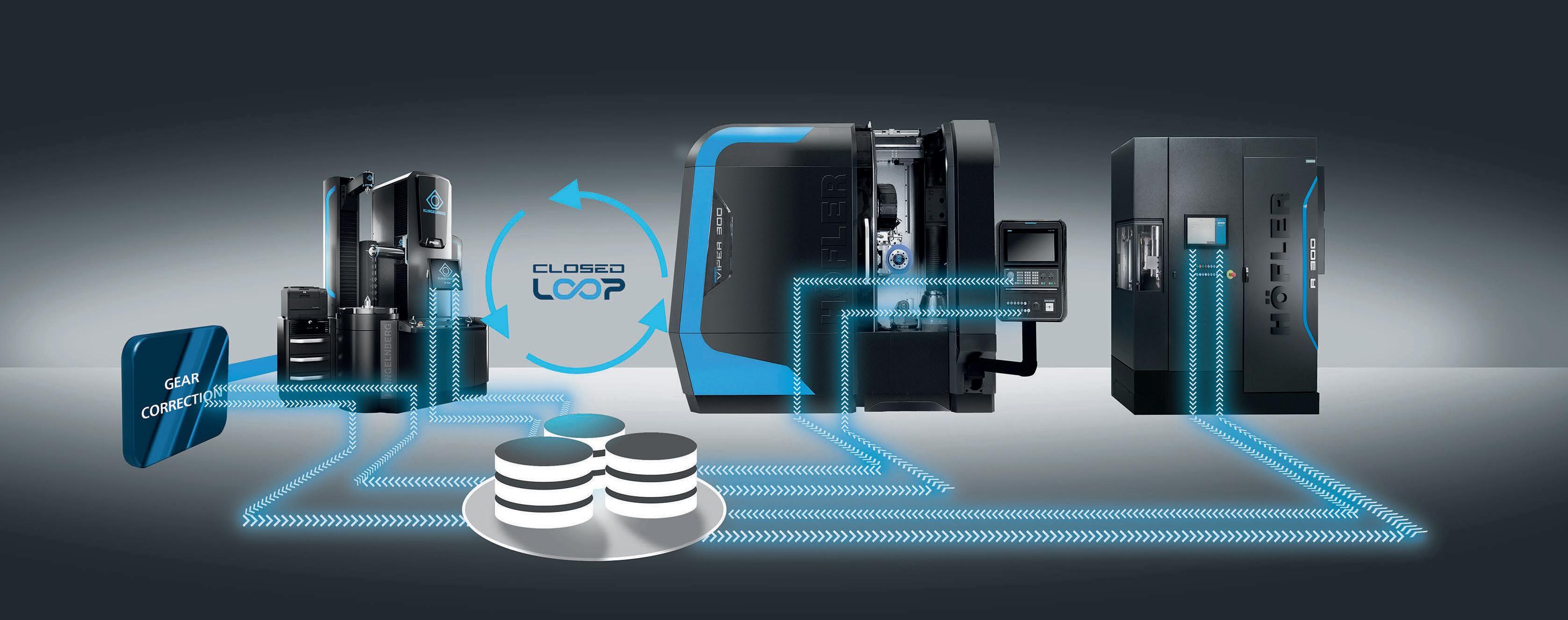
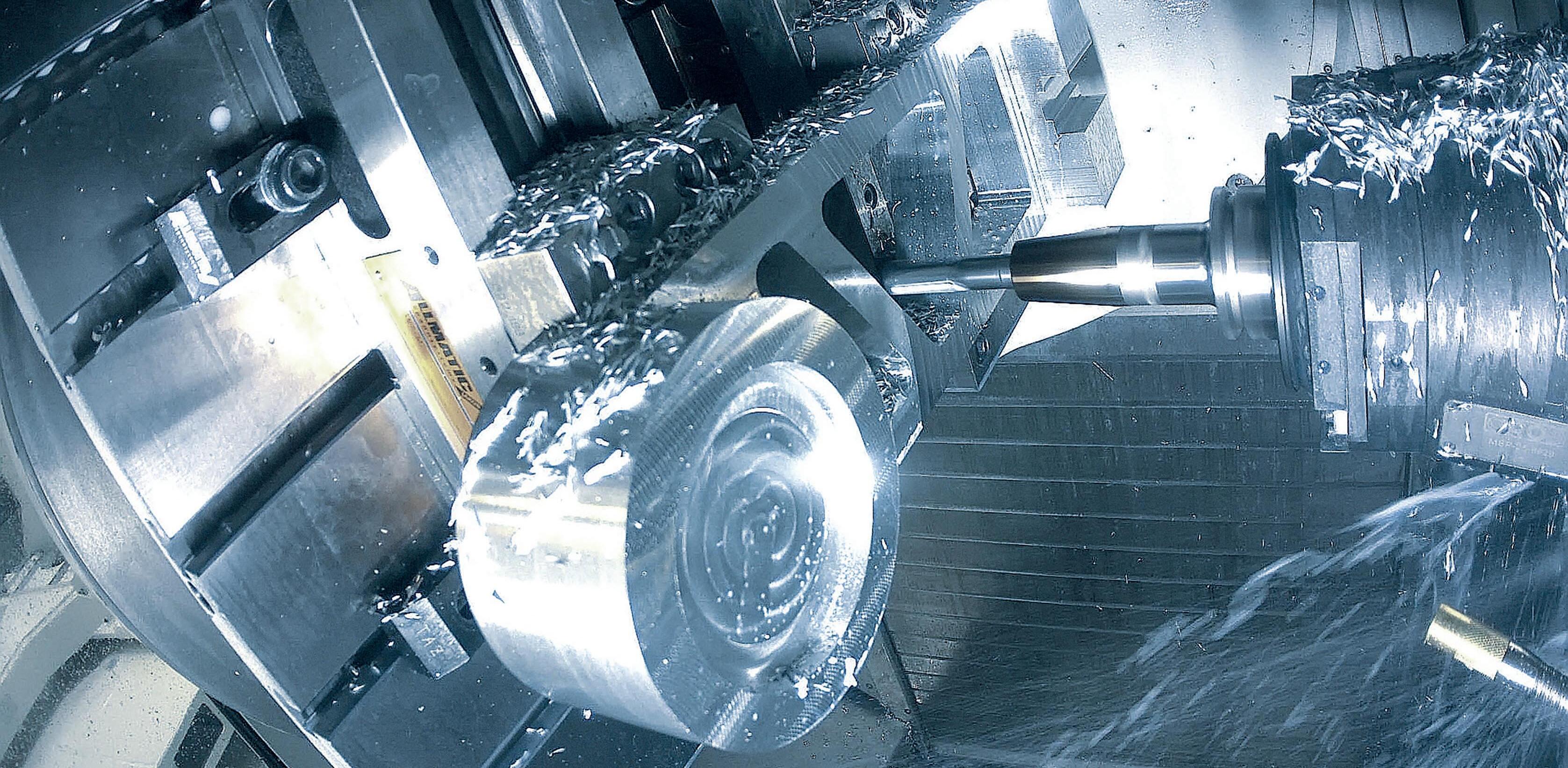
Up to now, the focus has been on machine automation for more productivity. A CNC-controlled 5-axis milling machine machines workpieces extreme- ly quickly. It can be used so skilfully that hardly any residual material remains. Mechanical engineering is already more productive as a result. And: noticeable successes can be achieved along the entire production chain. Because what is often overlooked: The machine is only the last station on the production path of a workpiece. In digital form, it has already passed through many process stations from the design stage to the machine shop, Figure 1. Since they are all working towards machine production, modern automation solutions start at the CAD/CAM process: They achieve an increase in efficiency of up to 80 %.
Setting digital standards
The key to more efficient production is process automation. It is based on future-proof standards and modern digitisation strategies. Instead of individual manufacturing islands, the measures address the entire process chain of a machine shop. The result: an ideally controlled, stable CAD/CAM process. Once standards have been set, they interlock smoothly at all stations. The manufacturing process is automated, which reduces the burden on skilled workers enormously.
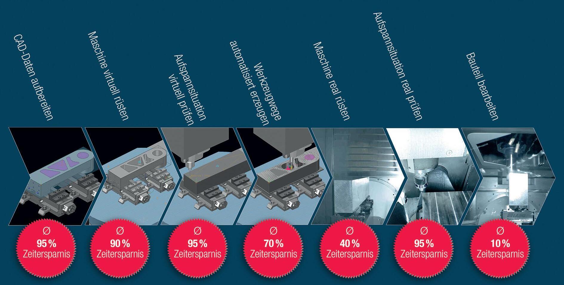
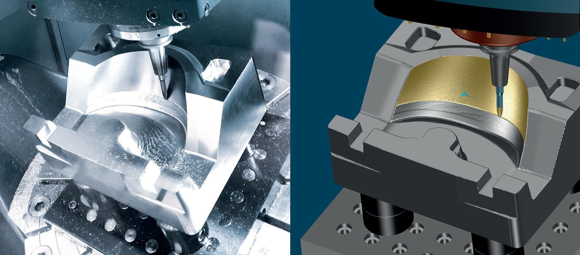
In concrete terms, this can be demonstrated with a digital CAD model of a workpiece, Figure 2. All process stations have one thing in common: they work on and with the CAD model. So the model is predestined to manoeuvre itself intelligently through the process. A practical example shows the efficiency potential at all stations – and what an integrated CAD/CAM system contributes to it.
The ideally controlled CAD/CAM process
Stage 1 – Preparing CAD data
Data preparation begins with reading the CAD data into the CAD/CAM system. All repeat tasks for this are stored there in CAD templates. Templates can be extended as required, individually configured and allow manual intervention. The only thing users have to do is select the component and specify the machining direction. The system takes care of the preparation automatically and provides the blank, extensions, top surfaces, zero point, clamping situations and more.
Stage 2 – Setting up the machine virtually
Parametric set-up means that the workpiece blank, finished part or clamping device have been fed in from the previous process station. The blank is automatically positioned via the connection points created there. For more complex set-ups with few repetitions, plausibility checks ensure the result. The CAD/CAM system automatically accesses libraries of tools, clamping devices, pre-configured machines and post-processors. It thus works with exact digital twins that contain all components and parameters.
Stage 3 – Checking the clamping situation virtually
The correct reference point can already be determined during CAM programming (and not just in the machine shop). With the measuring points from the data preparation, the dimensions can be checked and the entire clamping situation can be controlled directly from the NC program.
Stage 4 – Automated generation of toolpaths
The prepared CAD data flows directly into the automated CAM programming.
CAM templates make the user‘s work easier by automatically processing frequently used NC sequences and technologies. With a „feature scan“, for example, the CAD/CAM system recognises all 2.5 D machining operations. Instead of tedious manual work, the automatic element selection creates suitable holes and threads according to the geometry and predefined colours.
For this purpose, the software accesses libraries in which users store tried and tested production sequences. Step by step, the machine builder receives his internal manufacturing knowledge standardised in digital templates. The work plan template is created with one click, including NC programmes and tool paths. Without additional time expenditure – because if the software does not find any milling areas for contact surfaces, this job remains deactivated.
Bonus: While the calculation is running in the background, the user is already machining another component. The result is safe because an integrated NC simulation checks the NC programmes for collisions. It verifies the control information directly in the CAD/CAM system.
Stage 5 – Setting up the machine in real time
Checked NC programs are sent to the machine in control format. The result of the virtual setup is available to the machine operator without loss of information. The digital documentation provides clear information:
• The clamping position is defined.
• All clamping devices and tools are defined,
• Measuring points are defined,
• If the tools are already measured in advance, setup is even faster.
Station 6 – Checking the real clamping situation
The calibration of the workpiece zero point is fully automated. The NC program takes over inspection tasks that have already been created in the CAD/CAM system. This avoids application errors and minimises set-up times. Unsuitable clamping situations are reacted to flexibly: The CAM programmer uses parametric templates to quickly generate – for example –an alternative blank. The system adjusts everything else automatically.
Stage 7 – Mechanical production of the component
After starting, an optimised, safe and suitable NC program is executed. The machine can fully exploit its potential with highly dynamic and fast traverse movements, short tools as well as maximum possible feed and minimum retraction movements. Monitoring or programming on the control system is not necessary. The machine operator is free to concentrate on other tasks.
Afterwards, an integrated quality check starts, which has been directly incorpora- ted from the NC programming. The machine reacts independently to measurement results and automatically performs any correction loops – without resources and with logged measurement results.
Saving resources reduces costs

CAD/CAM processes that are automated in this way generate high levels of speed, safety and accuracy – and at the same time release skilled workers. Monotonous and repetitive processes are outsourced to templates, which avoids errors. This type of automation facilitates the division of labour: less experienced employees can create the majority of CAM programmes – such as 2.5D machining or 3-axis roughing programmes – fully automatically. Experienced users take care of more complex work. The targeted use of resources and manpower reduces costs.
Automation is necessary to safely „move into the future“. But it reaches its limits when motion sequences are too complex and tedious or workpieces are too individual. Then human skills such as creativity, flexibility and a logical mind for quick decisions remain in demand.
Scalable implementation
Mechanical engineering is already manufacturing more efficiently with automated machines and techniques today. But urgent day-to-day business often sets limits to the implementation of futureproof solutions. In such cases, a service partner and process supplier is recommended, one who can deliver the necessary flexibility with maximum effectiveness using scalable approaches. Up to 85 % more efficiency is possible with process automation in mechanical engineering. Scalable automation „as a managed service“ makes this affordable for SMEs. www.tebis.com/de
E-mobility is „electrifying“ at EMO Hannover 2023