
4 minute read
Efficient tool repair


Where massive forces are at work, even the hardest component will eventually give way. In use, turbine blades develop cracks, shafts get dented and punching tools deform at the edges. With modern additive manufacturing (AM) processes, such damaged areas can be repaired efficiently and the worn component made ready for use again.
Efficient repair
Advertisement
Laser-Powder Directed Energy Deposition“ (LP-DED) in particular has become established as an efficient process for repair tasks of this kind. A laser beam is used to create a molten pool into which a nozzle conveys a powdery, usually metallic filler material. This melts in the molten bath, and movements of the nozzle or the component create welding beads, twodimensional coatings and more complex 3D structures layer by layer. Thus, a wide range of components can be repaired with LP-DED by local build-up welding.
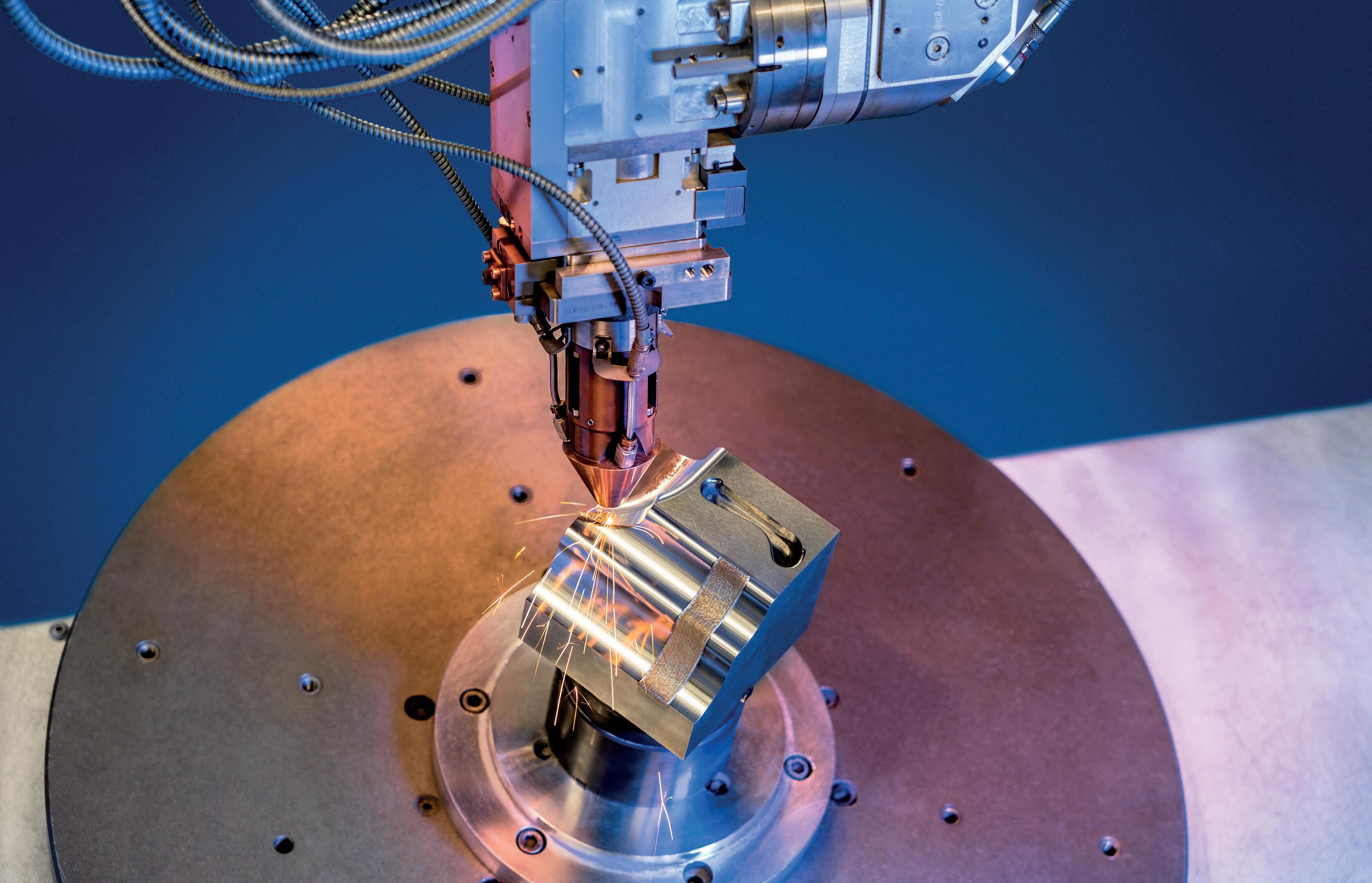
For simple geometries such as running or sealing surfaces on shafts, the process is well established and widely used in industry. But even for expensive components such as stamping or forming tools, which are found in automotive engineering, for example, the repair of localised damage using DED can be worthwhile (Figure 1). However, the hurdles to efficient use of the process are significantly higher here due to complex geometries and individual damage patterns such as indentations, chipped edges or deformations.
The repair process chain
For such repair tasks, a process chain like this usually has to be run through: 1) The defective component is 3D scanned, including its damaged area. 2) The component is prepared for repair (e.g. by grinding or milling out the damaged area). 3) The prepared component is 3D scanned again. 4) The 3D scan data thus generated is processed, detecting the defective areas and generating a differential volume that distinguishes the nominal and actual state. 5) An additive LP-DED repair process is planned in a CAM program. 6) The repair process is carried out. 7) The repaired component is heattreated and reworked.
In this chain, steps 4 and 5 in particular pose challenges. It is not easy to derive a weld path from a simple 3D scan. It is true that the recording and measurement of geometries by laser scanning or photogrammetry is standard for many applications today. But the resulting large amounts of data are often only used for visualisation or measurement purposes. In order to use them for repair processes, the scan data must be processed, aligned and converted into parameterised 3D models. Only then can the path planning for the repair process be carried out in a CAM programme. This process of converting 3D images into CAD models is called „reverse engineering“. It is still carried out manually to a large extent, which requires trained specialists and a lot of time. For highly individual components, the repair outlay is therefore often very high.
Great demands due to the materials
In addition, the actual repair process is complicated by welding and material challenges. Moulding tools are often made of cold-work or hot-work steels with relatively high carbon contents. Although the carbon content brings with it good hardenability, it also reduces the weldability of the material, which is problematic for repair welding. This is all the more true because the repaired areas must meet the requirements for durability and hardness, just as the whole original component did.
Researchers at the Fraunhofer Institute for Production Systems and Design Technology (IPK) are addressing these chal- lenges with an end-to-end repair solution that can be automated. Thanks to scan engineering with automated component recognition and geometry-based modelling as well as modern AM processes, defective components can be made ready for use again with little technical effort.
3D scanning + reverse engineering = Scangineering
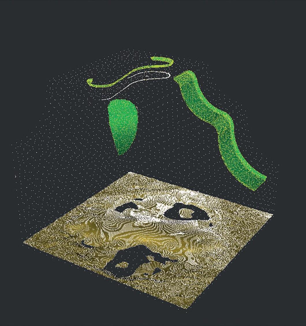
The reverse engineering process known as „Scangineering“ is an in-house development by Fraunhofer IPK. In this process, intelligent algorithms are used to pre-process, align and parameterise 3D scan data of components. This means that a geometry-based and thus manipulable 3D model is generated from the point clouds of a laser scan (Figure 2), which can be loaded into a CAD programme, for example. Users can intervene in the conversion process at any point as „input providers“ and for analysis. At the same time, they are spared manual and repetitive steps. By means of scan engineering, complex components, but also other objects such as machines or even buildings, can be easily and quickly imaged as useful virtual models.
CAM planning: Calculating tool paths

For automated component repair, the additive repair processes are planned in the next process step on the basis of the models. The detected geometric defects are used to calculate the tool paths and welding commands for the additive assembly. The mathematically determined volumes, surfaces and curves reduce the need for additional auxiliary geometries to be created and simplify and accelerate the programming process: coating surfaces are clearly defined and can be selected, complete differential volumes can be programmed by building them up layer by layer or complex curves can be used as support curves for the alignment of tool paths. Tool paths can be verified by means of build-up simulation and checking of travel paths, and any collision points can be detected and eliminated in advance.
Additive repair process and rework
The final step is the design of the process parameters and the actual component repair. Here, materials engineering knowhow is required to ensure high quality metallurgically and a durable repair: material-specific properties must be taken into account. The high carbon content in tool steels, for example, favours high hardness values – these are desirable to increase service life. However, with conventional repair welding, for example with arc processes, the high heat input in combination with the carbon content and other alloying elements can lead to cracks in the component. Laser-based processes such as LP-DED can be advantageous here: The high energy density and the resulting low heat input reduce the tendency to crack, the size of the heataffected zone, the influence on the base material, and the degree of mixing of base and filler material. Furthermore, the selection of the filler material is not limited to the alloy of the base material. www.ipk.fraunhofer.de


