Table 7: Status, Maintenance and Error Code Screens Display Mode
Description
DIAGNOSTICS INPUTS
Input Status
Float Hydro Glide High Gear Aux Detent Air Filter Clog Hyd Filter Clog High Hyd Temp Engine Pressure
Alternator KP Ingnition Run KP Ignition Start KP Seat Switch KP Restraint Bar
Displays input information from electronic control modules, showing real-time machine component/ control state. Status colors indicate the following: • Green – Active • Black – Inactive
Output Status
DIAGNOSTICS OUTPUTS High Gear Self Level Hydro Glide Fuel Pump Glow Plug Starter All Tach Lock All Tach Unlock
Float Marker Lts Rear Work Lts Front Work Lts KP Beacon Lts KP Dome Lt Disable Park Brake Tilt/Lift
Displays output information from electronic control modules, showing real-time feedback state of machine components. Status colors indicate the following: • Green – Active • Black – Inactive. • Yellow – Standby or Not Applicable • Red – Short Circuit
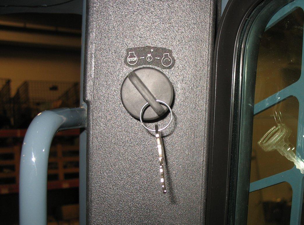
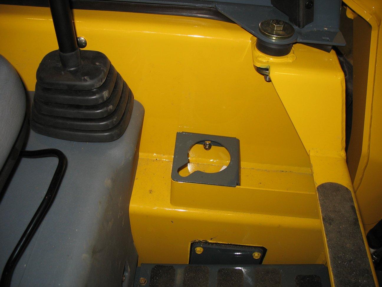
Controls Ignition Keyswitch The Ignition keyswitch is located near the top of the right door pillar. Ignition keyswitch positions are: •
OFF Position : With the key turned fully counterclockwise, power from the electrical system is disconnected from the controls and instruments. This is the only position from which the key can be inserted or removed. STOP
Figure 21 – Ignition Keyswitch
•
ON/RUN Position : With the key turned one position clockwise from the OFF position, electrical power is supplied to all controls and instruments.
•
START Position : With the key turned and held fully clockwise, the electric starter engages. Release the key to ON/RUN position when the engine starts.
57
50950264/G0521