2 minute read
Auxiliary Hydraulic System

from Gehl RT165 RT165 (EU) RT165 X-Series Compact Track Loader Operator’s Manual 50950264 - PDF DOWNLOAD

Auxiliary hydraulics are used with attachments requiring hydraulic power.
Always be sure the auxiliary hydraulic control is in neutral before starting the engine or disconnecting the auxiliary hydraulic couplers.
Auxiliary Hydraulic Couplers
Auxiliary hydraulic couplers (Figure 47) are located on top of the lift arm on the left side.
Note: Cover (G) is not present on all machines.

Auxiliary Hydraulics Control
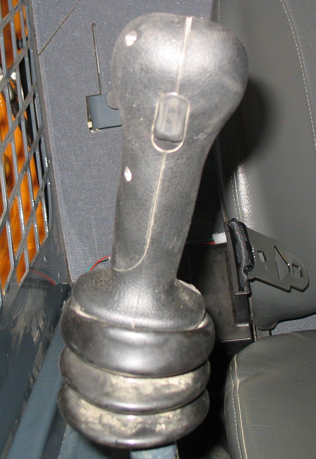


Rocker switch (F, Figure 48) controls the direction and amount of auxiliary hydraulics flow.


Auxiliary hydraulics control is proportional: the farther switch (F) is moved from center, the higher the flow through the auxiliary circuit. Flow direction is reversed when rocker switch (F) is moved in the opposite direction.
To latch continuous auxiliary hydraulic flow, hold rocker switch (F) fully on in either direction and push and hold trigger button (G) for five seconds. When the rocker switch and trigger are released, continuous flow should be enabled.
Note: Continuous flow amount is controlled using engine speed.
To cancel continuous flow, either push trigger button (G) or move rocker switch (F) in either direction.
High-Flow Auxiliary Hydraulic Control (Option)
In addition to a standard-flow auxiliary hydraulic system, loaders may be equipped with a reversible high-flow auxiliary hydraulic system. The couplers are located on top or inside of the right lift arm. The high-flow auxiliary hydraulic system is used for operating certain hydraulic attachments (e.g., cold planer, snowblower) that require higher flows.
Reverse Iconforward Icon
Figure49 – High-Flow Control Buttons
The high-flow auxiliary switch controls the direction of hydraulic oil flow. Push the right button for forward flow (J, Figure 49), or the left button for reverse flow (I, Figure 49). Pushing the right button will pressurize the high-flow male coupler. To disengage, push and release the button. Turning off the machine, raising the restraint bar, or restarting the engine will also reset the high-flow to neutral.
Only connect high-flow attachment couplers to the high-flow auxiliary couplers.
Before Starting the Engine
Warning
Before starting the engine and operating the machine:
• Review and comply with all safety recommendations in the Safety chapter of this manual.
• Know how to stop the machine before starting it.
• Fasten and properly adjust the seat belt(s) and lower the operator restraint bar.
Before starting the engine and running the machine, refer to “Safety Equipment” starting on page 39 and “Indicators and Controls” starting on page 47. Become familiar with the safe operation of the machine and the various operating controls, indicators and safety devices on the machine.
Operational Checks
Pre-Start Checks
Complete the following checks before starting the engine and using the machine. Correct/ repair any problems before using the machine.
Table 12: Pre-Start Checks
Check
Fuel tank filled?
Engine oil level correct?
Hydraulic system oil level correct?
Engine coolant level correct?
Windshield washer reservoir filled?
Grease fittings properly lubricated?
V-belt condition good/tension adjustment correct?
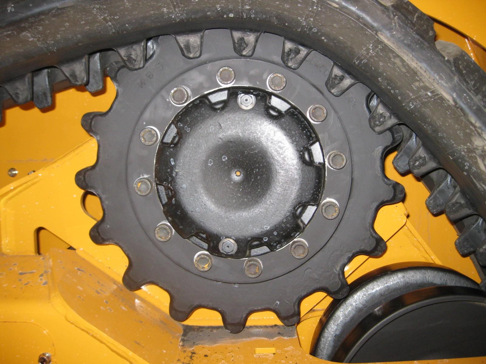
Track condition good?
Lights, signals, indicators, warning lights, indicators and horn operating properly?
Windows, lights and steps clean?
Attachment securely fastened to hitch?
Overall machine condition (including attachments) for bends, cracks, broken, loose or missing parts, etc.
Refer To:
“Adding Fuel” on page 139.
“Checking Engine Oil Level” on page 137.
“Checking Hydraulic Oil Level” on page 147
“Checking Coolant Level” on page 145
“Windshield Washer Reservoir” on page 158.
“General Lubrication” on page 132.
“V-Belt Maintenance” on page 144
“Control Keypad” on page 48, “Controls” on page 59.
“Connecting Attachments” on page 98