4 minute read
Safety Interlock System (Hydraloc™)

from Gehl RT165 RT165 (EU) RT165 X-Series Compact Track Loader Operator’s Manual 50950264 - PDF DOWNLOAD

NEVER attempt to bypass or defeat the safety interlock system. Serious personal injury or death could result.
The Hydraloc™ safety interlock system provides for operator safety. The interlock system:
•Prevents the engine from starting unless the operator is sitting in the operator’s seat with the restraint bar lowered.
•Disables the lift arm, auxiliary hydraulics, attachment tilt and wheel drive hydraulics if the restraint bar is raised, the ignition keyswitch is turned off or the operator’s seat is not occupied.
Note: Once started, the auxiliary hydraulic circuit will stay detented in the “on” position for continuous operation with the restraint bar raised and operator out of the seat. See“Auxiliary Hydraulic System” on page80.
Safety Interlock System Test
Each time before using the machine, check the safety interlock system daily for proper operation:
Seat Switch Test
With the engine off and the restraint bar lowered, unfasten the seat belt, and lift your weight off the seat. Try to start the engine. If the engine starts, turn off the engine, troubleshoot and correct the problem. Contact your dealer if necessary.
Restraint Bar Test
With the engine running, raise the restraint bar. Test each of the controls. The lift arm, hitch and drive should move only slightly. If there is any significant movement, troubleshoot and correct the problem immediately. Contact your dealer if necessary.
Parking Brake
The machine is equipped with a springapplied, hydraulically-released parking brake. The parking brake is automatically applied when the restraint bar is lifted, the operator’s seat is not occupied, or the engine is shut off. The brake can also be applied manually by pressing button (K, Figure 9) on the control keypad on the right door pillar.
Button (K) is illuminated when the ignition keyswitch is in the ON/RUN position and the parking brake is applied.
ROPS/FOPS
The ROPS/FOPS (Roll-Over/Falling Object Protective Structure) is designed to protect the operator from falling objects and during a tip-over accident, if the operator is secured inside the operator’s compartment by the seat belt and restraint bar.
Warning
Never operate the machine with the ROPS/FOPS raised or removed.
Rear Window Emergency Exit
To use the emergency exit function, pull on yellow warning tag (M, Figure 10) at the top of the window and remove the seal. Push or kick out the window to allow exit from the machine.

to reinstall the window, see your local automotive glass specialist.
Lift Arm Support
The lift arm support prevents the raised lift arm from lowering unexpectedly. The lift arm support must be applied whenever the lift arm is left in the raised position.
A falling lift arm could result in severe injury or death. Never allow anyone under a raised lift arm without the lift arm support applied.
If the lift arm must be left in the raised position, BE SURE to properly apply the lift arm support.
The operator must not leave the operator's position if the lift arm is in the raised position unless the lift arm support is properly applied.
Applying and disengaging the lift arm support requires two people – one person inside the machine and another person outside the machine to apply and/or disengage the support device.
The lift arm support must be kept in proper operating condition at all times.
Important: A second person on the outside of the machine is required to assist with applying the lift arm support.
Engage Lift Arm Support
1.Empty and remove the attachment (See “Connecting Attachments” on page98).
2.Bring the machine to a complete stop on a level surface.
3.Lower the lift arm fully.
4.Stop the engine.
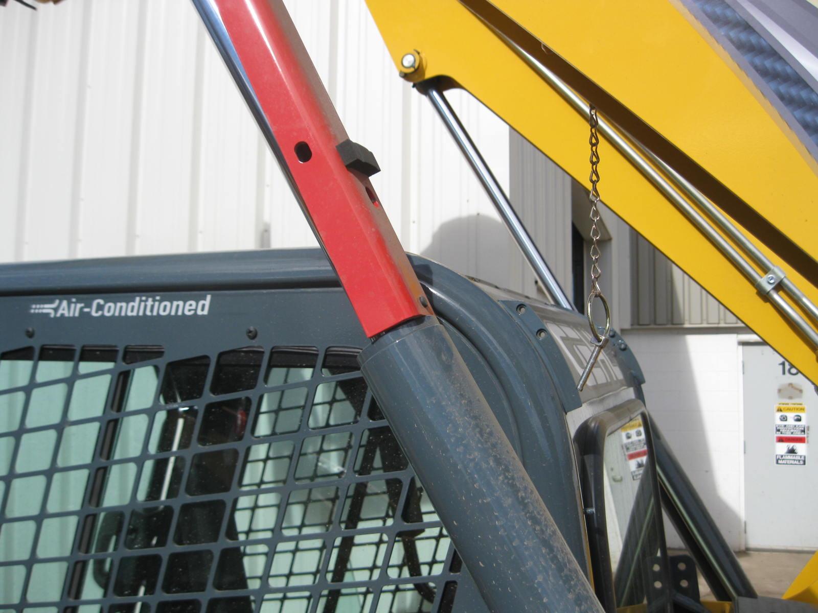
5.Have an assistant remove the lift arm support from its storage location on the left side of the machine. Remove lynchpin (S, Figure 11) holding lift arm support (T) up against the lift arm. Allow lift arm support (T) device to pivot down into contact with the lift cylinder.
6.Restart the engine.
7.Use the lift control to raise the lift arm until lift arm support (T, Figure 12) drops over the end of the lift cylinder and around the cylinder rod.
8.Slowly lower the lift arm until the free end of the support device contacts the top end of the lift cylinder (U).
9.Check the support device to ensure it is secure against the cylinder end.
10.Stop the engine.
11.Move the lift control to verify the control does not cause the lift arm to move.
12.Unfasten the seat belt, remove the ignition key and take it with you. Exit the machine using the hand-holds.
Disengage Lift Arm Support
The safest method of installing and removing the lift arm support device requires two people – one person inside the machine and another person outside the machine to disengage the support device.
1.Start the engine.
2.Raise the lift arm fully.
3.Stop the engine.
4.Verify that the lift arm is being held in the raised position by the safety interlock system.
Important: With the key switch OFF and the solenoid valve working properly, the lift arm will stay raised when the lift control is moved to lower the lift arm. If the valve does not hold the lift am and it begins to lower do not leave the operator’s compartment. Instead, lower the lift arm against the lift arm support and exit the machine. Then, contact your dealer immediately to determine why the lift arm lowers while the key switch is OFF.
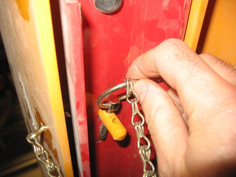
5.Have an assistant raise lift arm support (T, Figure 13) until it contacts the lift arm. Reinstall lynchpin (S) through post (V) on the lift arm to secure lift arm support (T) in the storage position.
6.Fold lynchpin ring (W) over post (V) to lock lynchpin in place.

To prevent damage to the lift cylinder, do not lower lift arm until the lift arm support is secured in the storage position.
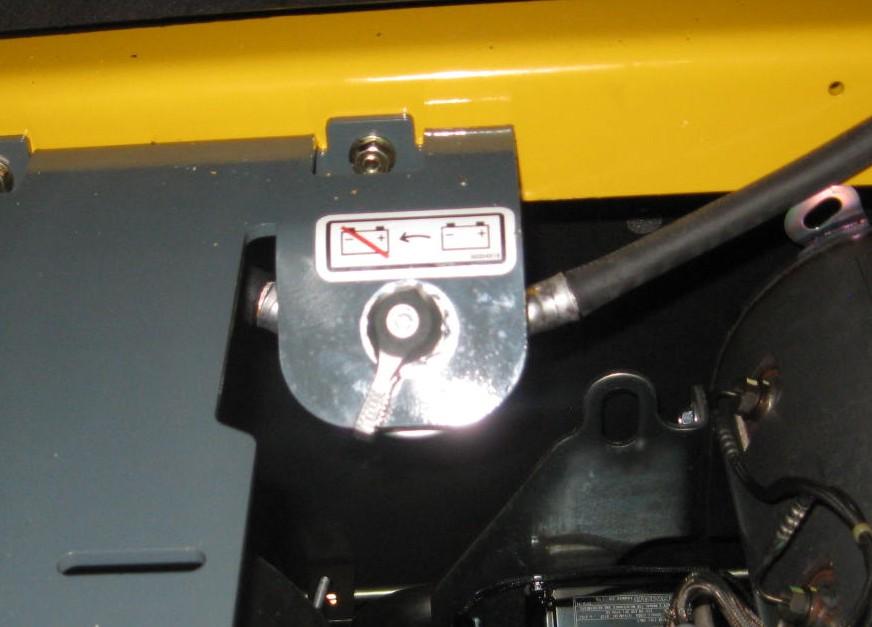
Battery Disconnect Switch
The battery disconnect switch is located in the engine compartment. Turning the switch to the OFF position disconnects the battery from the electrical system.
Always turn the switch to the “OFF” position when parking the machine inside an enclosure.
Indicators And Controls
Become familiar with all controls before operating the machine. Know how to stop the machine before starting it. The machine is designed and intended to be used only with Manitou-approved attachments or accessories. Manitou cannot be responsible for operator safety if the machine is used with unapproved attachments.
Figure15 – Controls (Hand/Foot Control Option Shown)
A. Accessory Keypad (page49)F. HVAC Vent NozzleK. Right Hand Control (page65)
B. Ignition Keyswitch (page57)G. Cup Holder
C. Information Center Electronic Display (page51)
H. Foot Controls (page65)
D. Control Keypad (page46)I. Throttle Control (page58)
E. Electrical Accessory SocketJ. Left Hand Control (page65)
L. Operator’s Seat (page39)
M. Optional Lights/Lockout Keypad (page50)