9 minute read
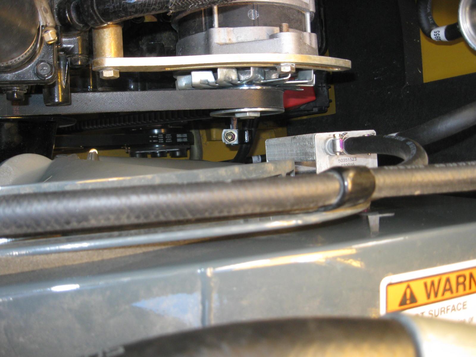
Engine Mounting Hardware Inspection

from Gehl RT165 RT165 (EU) RT165 X-Series Compact Track Loader Operator’s Manual 50950264 - PDF DOWNLOAD

Warning
Perform the Mandatory Safety Shutdown Procedure. Allow hot engine and hydraulic system components to cool before servicing.
All bolts that secure the engine mounting brackets to the engine and the chassis should be checked and re-tightened as necessary.
Checking Engine Oil Level
Check the engine oil level daily before starting the machine, or after every 10 hours of use.
1.Park the machine on a level surface.
2.Perform “Mandatory Safety Shutdown Procedure” on page14.
3.Wait until the engine has cooled.
4.Open the engine access cover and rear door.
5.Twist engine oil dipstick (E, Figure 90) counterclockwise to unlatch it. Remove the dipstick from the engine.
6.Wipe the dipstick with a clean cloth and replace it in the engine. Push it in until it is fully inserted.
7.Remove the dipstick again. The oil level should be within the “Add” (G) and “Full” (H)markings.
8.If the oil level is below the “Add” marking: a.Clean the area around the oil fill cap (F)with a clean cloth. b.Remove fill cap (F). c.Add oil through the fill cap opening until the level reaches the “Full” mark. d.Replace and tighten fill cap (F).
Important: Do not over-fill the engine with oil; engine damage could result.

Changing Engine Oil and Filter
Refer to the “Maintenance Schedules” on page127 for the service interval for replacing the engine oil and filter.
1.Park the machine on a level surface.
2.Perform “Mandatory Safety Shutdown Procedure” on page14.

3.Wait until the engine has cooled, but is not completely cold.
Note: Oil drains faster and more completely when warm.
4.Engine oil drain plug (A, Figure 91) is located inside the left rear wheel well, on the outside of the chassis behind the left rear wheel.
5.Position a waste oil collection container under the engine oil drain plug to catch draining oil.

Important: Dispose waste engine oil according to environmental laws, or take to a recycling center for proper disposal. DO NOT pour waste engine oil onto the ground or down a drain.
6.Remove drain plug (X) or (A) and allow engine oil to drain into the waste oil collection container.

7.Remove oil filter (W, Figure 92), using a filter wrench if necessary. Carefully clean the filter head mounting surface with a clean cloth.
8.Put clean oil on the new oil filter gasket. Install the filter and tighten 3/4 of a turn past the point where the gasket contacts the filter head.
9.Reinstall and tighten the drain plug.
10.Clean the area around oil fill cap (E, Figure 90). Remove oil fill cap (E) and add the recommended type and amount of oil. See “Fluid Capacities/Lubricants” on page187. Replace and tighten oil fill cap (E) after the oil is added.
Note: Oil capacity listed is approximate. Always verify proper oil level with the engine oil dipstick.
Important: Do not over-fill the engine with oil; engine damage could result.
11.Start the engine and let it run for several minutes at low idle. Watch for leaks at the oil filter and drain plug. Stop the engine and wait for it to cool.
12.Check the oil level. Add oil if necessary until the oil level is at the “Full” mark (H, Figure 90) on the dipstick.
Fuel System Maintenance
Diesel fuel is flammable. Keep the machine away from open flames. Do not smoke when refueling or when working on the engine. Stop the engine before fueling.
Wear eye protection. The fuel system is under pressure and fuel could spray out when removing any fuel system component.
Wipe up spills immediately. NEVER use a shop rag to catch draining/ leaking fuel. Vapors from the rag are flammable and explosive.
Failure to follow these instructions can cause fire and result in injury or death.
Use only proper types and grades of diesel fuel (See “Fluid Capacities/Lubricants” on page187).
Note: The fuel tank is filled at the factory with United States off-road grade diesel fuel, which is dyed red for identification. It may take several fillings of the fuel tank before the red dye is purged from the fuel system.
Adding Fuel
Keep open flames and sparks away from fuel. Static electricity can produce dangerous sparks at the fuel-filling nozzle. Do not wear polyester, or polyester-blend clothing while fueling. Before fueling, touch the metal surface of the machine away from the fuel fill to dissipate any built-up static electricity. Do not re-enter the machine but stay near the fuel filling point during refueling to minimize the build-up of static electricity. Do not use cell phones while fueling. Make sure the static line is connected from the machine to the fuel truck before fueling begins.
WARNING
Ultra-Low Sulfur Diesel (ULSD) poses a greater static ignition hazard than earlier diesel formulations. Avoid death or serious injury from fire or explosion; consult with your fuel or fuel system supplier to ensure the entire fuel delivery system is in compliance with fueling standards for proper grounding and bonding practices.

1.Perform the “Mandatory Safety Shutdown Procedure” on page14.
2.Lift the engine cover.
3.Using the ignition key to unlock fuel cap (F, Figure 93) and remove the fuel cap from the fuel filler neck.
Note: On Model R135, fuel cap (F) is located under the engine cover.
4.Fill the fuel tank by adding fuel through the fuel filler neck opening.
Important: See “Fluid Capacities/ Lubricants” on page187 and the engine operation manual for proper fuels. Use of improper fuels can cause engine damage.
5.When the fuel tank is full, replace and lock fuel cap (F) in the fuel filler neck opening.
Important: To provide for proper fuel system venting, do not top off the fuel tank.
Water Separator Maintenance
NEVER service the fuel system while smoking, while near an open flame, or if the engine is hot.
Important: Water in the fuel system can cause severe engine damage. Drain water from the fuel filter/water separator whenever water is present.
Inspect the water separator daily, or every day before using the machine.
1.Perform the “Mandatory Safety Shutdown Procedure” on page14.
2.Wait until the engine has cooled.
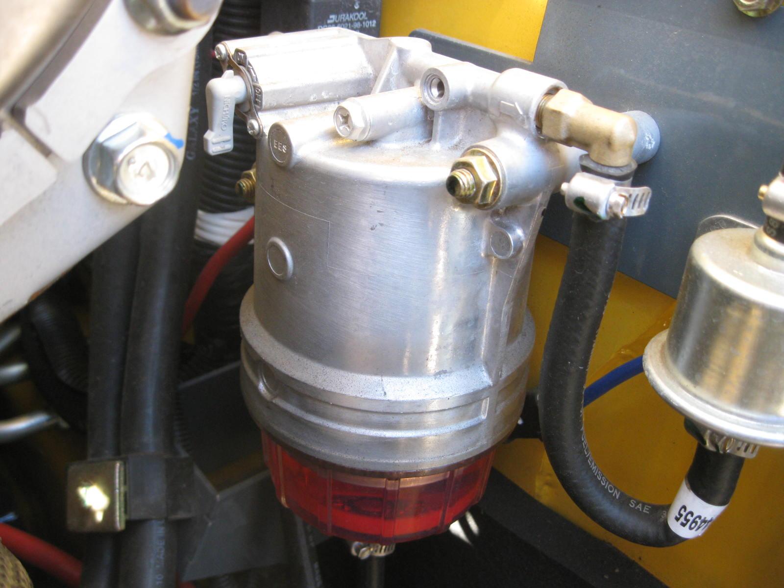
3.Inspect the water separator (Figure 94) for the presence of water:
•If the indicator ring (M) is at the bottom of the cup, no action is required.
•If the indicator ring (M) is floating off the bottom of the cup, water is present and needs to be drained.
4.If water needs to be drained, position a suitable collection container underneath the water separator drain.
5.Turn the fuel valve lever (V) on the water separator to the OFF position.
6.Loosen drain plug (N) at the bottom of the water separator. Allow water to drain until indicator ring falls to the bottom of the cup.
7.Tighten drain plug (N) and discard fuel/water according to environmental laws. Important: Dispose waste fuel according to environmental laws. DO NOT pour fuel onto the ground or down a drain.
8.Turn the fuel valve lever (V) on the water separator to the ON position.
9.Prime the fuel system by turning the ignition key to the ON position without starting the engine for 30 seconds. Repeat this step 3 times to ensure the fuel system is completely primed.
Do not use the starter motor to crank the engine to prime the fuel system. Damage to the engine starter motor, coils, pinion/ring gear could result.
10.Start the engine and check for leaks.
Changing Water Separator Filter
NEVER service the fuel system while smoking, while near an open flame, or if the engine is hot.
1.Perform the “Mandatory Safety Shutdown Procedure” on page14.
2.Wait until the engine has cooled.
3.Turn the fuel valve lever (V, Figure 94) on the water separator to the OFF position.

4.Unscrew the separator bowl from the housing and pull down on the existing filter to release it from the housing.
5.Install a new filter and reinstall the bowl.
6.Turn the fuel valve lever (V) on the water separator to the ON position.
7.Prime the fuel system by turning the ignition key to the ON position without starting the engine for 30 seconds. Repeat this step 3 times to ensure the fuel system is completely primed.
Do not use the starter motor to crank the engine to prime the fuel system. Damage to the engine starter motor, coils, pinion/ring gear could result.
8.Start the engine and check for leaks.
Changing Fuel Filter
Caution Warning
NEVER service the fuel system while smoking, while near an open flame, or if the engine is hot.
Important: Change the fuel filter every 500 hours of operation.
1.Perform the “Mandatory Safety Shutdown Procedure” on page14.
2.Wait until the engine has cooled.
3.Turn fuel valve lever (V, Figure 95) on the water separator to the OFF position.

4.Remove the fuel filter (W, Figure 96), using a filter wrench if necessary. Carefully clean the filter head mounting surface with a clean cloth.
5.Apply a coating of clean diesel fuel on the new fuel filter gasket. Install the filter and tighten 3/4 rotation past the point where the gasket contacts the filter head.
6.Turn fuel valve (V, Figure 95) on the water separator to the ON position.
7.Prime the fuel system by turning the ignition key to the ON position without starting the engine for 30 seconds. Repeat this step 3 times to ensure the fuel system is completely primed.
Do not use the starter motor to crank the engine to prime the fuel system. Damage to the engine starter motor, coils, pinion/ring gear could result.
8.Start the engine and check for leaks.
Engine Air Cleaner
Important: Failure to follow proper air filter servicing instructions could result in catastrophic engine damage.
Do not operate the engine without the air cleaner components installed or damage to the engine could occur.

Check the air cleaner intake hose and clamps, and the mounting bracket hardware daily to be sure they are properly tightened.
Check, and if necessary replace, the engine air filter after every 250 hours of use, or every 6 months, or if the filter is damaged, oil- or sootladen.
Be sure the air cleaner intake hose, clamps and mounting bracket hardware are properly tightened.
Changing Air Filter Elements
1.Perform the “Mandatory Safety Shutdown Procedure” on page14.
2.Wait until the engine has cooled.
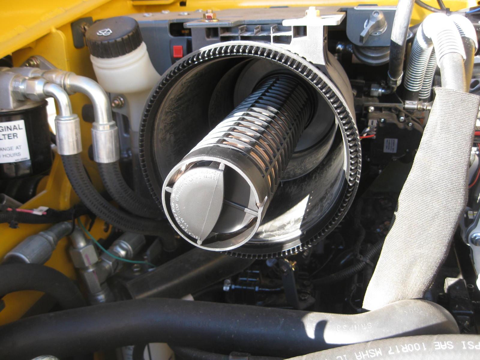
3.Unlatch clamps (J, Figure 97) on the air cleaner housing and remove the air filter cover (L).

4.Clean debris from inside the air cleaner housing and air filter cover.
5.Carefully remove the outer filter element (G).
6.Clean dirt from inside the air filter housing (M).
Important: To prevent debris from entering the engine intake manifold, do not remove inner filter element (H) while cleaning the inside of the housing.
7.Remove inner filter element (H) only if it needs replacement.
8.Check the inside of the housing for damage.
9.If applicable, install a new inner filter element (H). Make sure the sealing surfaces are clean and the new element is properly seated.
10.Install a new outer filter element (G). Make sure the sealing surfaces are clean and the new element is properly seated.
11.Replace air filter cover (L). Latch clamps (J). Make sure the cover is tightly secured and is seated properly in the housing.
12.Check the air cleaner intake hose, clamps and mounting bracket hardware are properly secured and tightened.
DPF Service (DPF Models)
DPF soot filter replacement is required when the DPF (Diesel Particulate Filter) Service Screen (Figure 98) displays.
Note: Contact your dealer when the DPF Service screen displays.
V-Belt Maintenance
1.Perform the “Mandatory Safety Shutdown Procedure” on page14.
2.Wait until the engine has cooled.
3.Inspect V-belt (F, Figure 99) for damage. If damaged, have belts replaced by an authorized repair shop.
4.Press on V-belt (F) mid-way between pulleys to check deflection. The belt should not deflect more than 8 mm (5/16 in.).
5.If deflection is more than 8 mm (5/16 in.): Loosen adjustment bolt (G) and rotate alternator (E) outward until V-belt tension is correct. Tighten bolt (G) and re-check Vbelt tension.
Cooling System
Important: Check the cooling system every day to prevent overheating, loss of performance or engine damage.
Checking Coolant Level
1.Park the machine on a level surface.
2.Perform the “Mandatory Safety Shutdown Procedure” on page14.
3.Wait until the engine has cooled.
Warning
Do not remove radiator cap when the coolant is hot. Serious burns could result.
4.Check the coolant level in the expansion reservoir (R, Figure 100). Coolant level must be between the full (T) and low (S) marks on the expansion reservoir. Add coolant to the expansion reservoir as required.

Important: The coolant system is specifically designed for coolant level top-off only through the expansion reservoir. Do not add coolant directly to the radiator.
Note: Use a low-silicate ethylene glycol-based coolant, mixed with quality water and supplemental coolant additives (SCAs) suitable for heavy-duty diesel engines. See “Fluid Capacities/Lubricants” on page187, “Coolant Compound Mixtures” on page193 and the engine operation manual for additional information.
Cleaning Radiator Fins
The radiator fins can become blocked during use which will lead to reduced cooling function and engine overheating. Clean the radiator cooling fins after every 250 hours or 6 months of operation, whichever occurs first.
1.Perform the “Mandatory Safety Shutdown Procedure” on page14.
2.Wait until the engine has cooled.
3.Open the rear door. Lift the engine cover.
4.Clean the radiator fins by blowing air/water through the fins from the rear of the radiator, toward the engine.
Important: Use caution! High pressure air/water can damage radiator fins.