2 minute read
Sprocket Tooth Wear and Track Life

from Gehl RT165 RT165 (EU) RT165 X-Series Compact Track Loader Operator’s Manual 50950264 - PDF DOWNLOAD

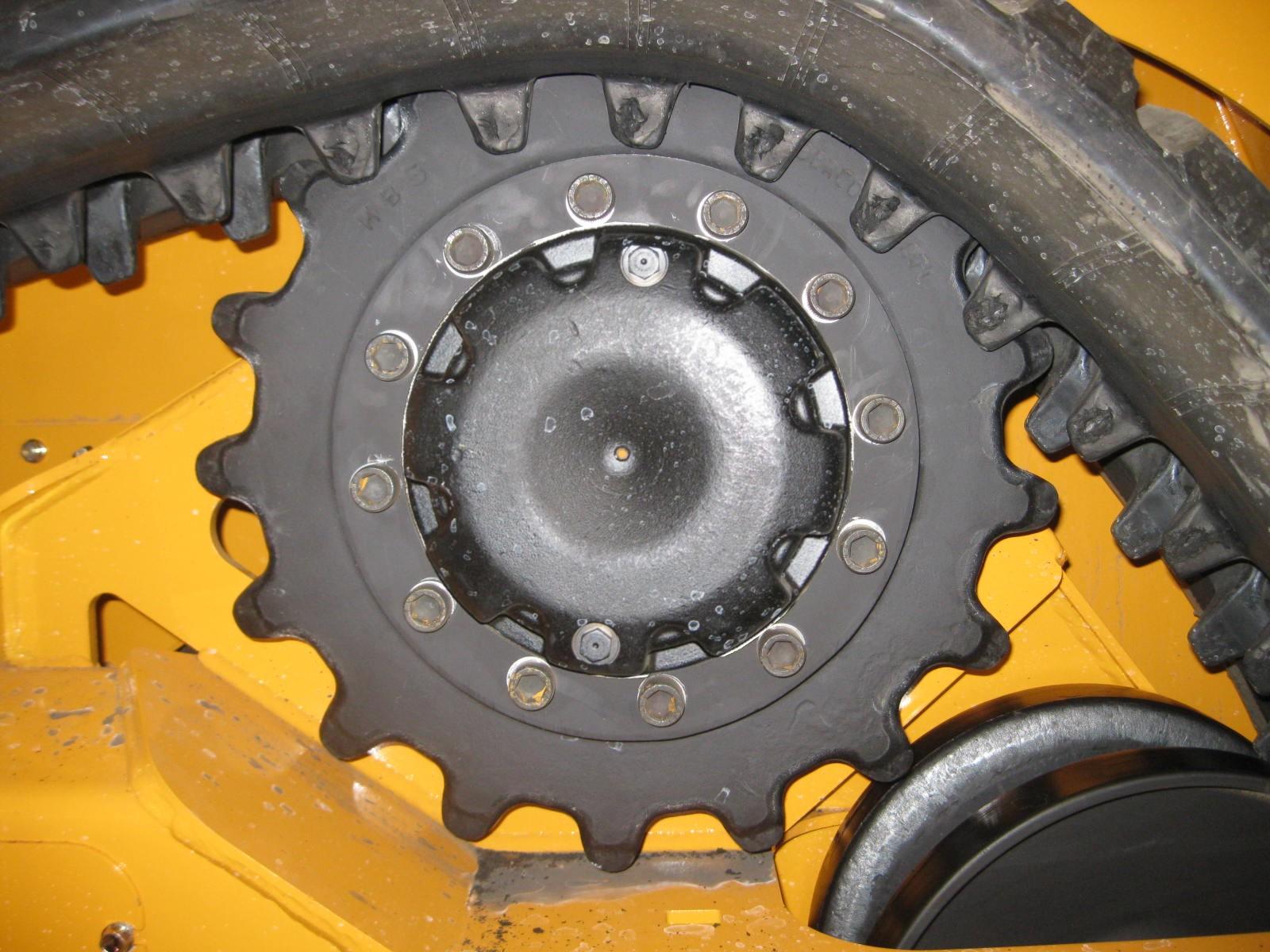
Worn sprockets are a typical cause of track damage and abnormal track noise. Check for sprocket wear often. Sprocket wear (B) normally occurs along the sides and crests of the sprocket teeth (C). Use the sprocket tooth wear gauge (A - Manitou part # 50309811), included with the machine, to determine exact sprocket tooth wear:
• Hold the sprocket tooth wear gauge (A) against the sprocket teeth at the centerline of the sprocket as shown in the photograph. Wear gauge (A) has the same profile as the teeth on a new sprocket.
• Sprocket wear is considered excessive if 1/8” (4mm) of material is worn from any point along the sprocket tooth profile.
• Sprocket wear is considered excessive if 1/8” (4mm) of material is worn from any point along the sprocket tooth profile.
• Worn sprockets cannot be repaired and should be replaced. Refer to the parts manual for your machine for sprocket service part numbers when ordering. Rotating sprockets by swapping them from one side to the other can extend their service life, provided the wear is limited to one direction of travel.

Important: New tracks perform better and last longer with new sprockets because the mating surface profiles are matched.
Always replace sprocket mounting hardware when replacing or re-attaching sprockets.
Lift Arm Operation
Refer to lift and tilt control information starting on page 61.
Do not lift loads exceeding rated operating capacity. See “Payloads/Capacities” on page 190.
The float mode can be used where the engine has stopped, is unable to be started, and lowering the lift arm is necessary to allow the operator to exit the machine. See “Lift Arm Float” on page 71.
Attachment Transport Position
Always carry loads in transport position to minimize the possibility of tipping or rollover accidents and unstable balance conditions that can cause loss of control.
Carry materials 200-300 mm (8-12”) above the ground (A, Figure 60), and adjust as necessary to clear obstacles. Generally, carry the load as low as safely possible. Tilt buckets back, as shown in Figure 60, to prevent spilling material.
Lift Arm Float
Make sure the bucket is lowered to the ground before activating the lift arm float. Activating float with an attachment raised will cause the lift arm to fall to the ground, which can cause severe injury or death.
WARNING
Do not drive forward with the lift arm float activated. Damage to the machine and/or loss of control can result.
Float allows the lowered lift arm to follow the ground contour while traveling over changing ground conditions. It is useful when grading surfaces while driving the machine in reverse.
Note: Lift arm float is not effective if the lift arm is lowered against the chassis frame. See “Lift Arm Float” on page 71 for details about the lift arm float control.
Hydraglide™ Ride Control System (Option)
Hydraglide™ cushions lift arm loads during transport. It provides a smoother ride over uneven surfaces.
When ride control is activated, the lift arm may drop slightly without a load, or several inches with a heavy load.
Do not use Hydraglide™ when using pallet forks.
Important: Do not use Hydraglide™ when digging. Precise control of the digging operation is difficult with the Hydraglide™ option activated.
Note: Hydraglide™ is not effective if the lift arm is lowered against the chassis frame. See “Hydraglide™ Ride Control System (Option)” on page 73 for details about Hydraglide™ control.