5 minute read
Table 7: Status, Maintenance and Error Code Screens

from Gehl RT165 RT165 (EU) RT165 X-Series Compact Track Loader Operator’s Manual 50950264 - PDF DOWNLOAD

Diagnostics Inputs
Diagnostics Outputs
Controls
Ignition Keyswitch
Input Status
Displays input information from electronic control modules, showing real-time machine component/ control state. Status colors indicate the following:
• Green – Active
• Black – Inactive
Output Status
Displays output information from electronic control modules, showing real-time feedback state of machine components. Status colors indicate the following:
• Green – Active
• Black – Inactive.
• Yellow – Standby or Not Applicable
• Red – Short Circuit
The Ignition keyswitch is located near the top of the right door pillar. Ignition keyswitch positions are:
• OFF Position : With the key turned fully counterclockwise, power from the electrical system is disconnected from the controls and instruments. This is the only position from which the key can be inserted or removed.
• ON/RUN Position: With the key turned one position clockwise from the OFF position, electrical power is supplied to all controls and instruments.
• START Position: With the key turned and held fully clockwise, the electric starter engages. Release the key to ON/RUN position when the engine starts.
Throttle Controls
On machines equipped with throttle knob (Q, Figure 22), engine speed is controlled with throttle knob and optional foot throttle (P, Figure 23), if installed.

Throttle knob (Q) is the primary throttle control. The throttle is set with the knob to the desired idle/run position.
On machines equipped with optional throttle pedal (P, Figure 23), the pedal can be used to increase engine speed whenever additional power is required. When the optional pedal is released, the engine returns to the speed set by throttle knob (Q, Figure 22).

Travel Drive, Lift and Tilt Controls
The machine is equipped with one of three control systems:
•T-Bar Controls: see “T-Bar Controls” on page59.
•Joystick Controls: see “Joystick Controls” on page62.
•Hand and Foot Controls: see “Hand and Foot Controls” on page65.
T-Bar Controls
On T-bar-equipped machines, the left T-bar controls the travel drive, and the right T-bar controls the attachment lift and tilt.


Table 8: T-Bar Controls
Ref. Control Description
ALeft T-Bar
BRight T-Bar
CTwo-Speed Selection Button
DHorn Button
EHydraglide™ Button
FINACTIVE
G Auxiliary Hydraulics Rocker Switch
H Auxiliary Hydraulics Continuous Flow Latch Trigger
Controls drive forward, reverse, turn, and speed. See “Drive Control (Left T-Bar)” on page60.
Controls lift arm raise/lower, float, and attachment tilt. See “Lift/Tilt Control (Right T-Bar)” on page61.
Toggles between high- and low-speed travel modes. See “Two-Speed Drive” on page67.
Activates horn.
Activates Hydraglide™. See “Hydraglide™ Ride Control System (Option)” on page71.
Button is inactive on T-Bar Controls.
Controls auxiliary hydraulics flow direction and amount. See “Auxiliary Hydraulic System” on page78.
Works with Auxiliary Hydraulics Rocker Switch to latch/ unlatch auxiliary hydraulics continuous flow. See “Auxiliary Hydraulic System” on page78.
On machines equipped with T-bar controls, the left T-bar controls the drive, and the right T-bar controls the lift/tilt.

Drive Control (Left T-Bar)

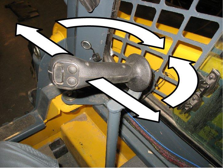
Forward, reverse, travel speed and turning maneuvers are controlled using the left Tbar (Figure 25):
A.To go forward, push the left T-bar forward.
B.To go in reverse, pull the left T-bar rearward.
C.To turn right, twist the control clockwise.
D.To turn left, twist the control counter-clockwise.
For gradual turns, twist the T-bar slightly; for sharp turns, twist the T-bar further.
Turns while moving forward or in reverse can be made by twisting the T-bar while also pushing it forward or pulling it back.
Moving the T-bar farther from neutral increases the speed steadily to the maximum travel speed.
Note: Tractive effort decreases as speed increases. To get maximum tractive effort, move the T-bar only slightly away from the neutral position.
Note: The engine will stall if the control is moved too far forward when loading the bucket.
Be sure the controls are in neutral before starting the engine. Operate the controls gradually and smoothly. Excessive speed and quick control movements without regard for conditions and circumstances are hazardous and could cause an accident.
Lift/Tilt Control (Right T-Bar)
Lift arm raise and lower, and attachment tilt are controlled using the right T-bar (Figure 26):
A.To lower the lift arm, push the right T-bar straight forward.
B.To raise the lift arm, pull the right T-bar straight rearward.
C.To tilt the attachment forward and down, twist the right T-bar clockwise.
D.To tilt the attachment up and back, twist the right T-bar counterclockwise.
The lift arm can be tilted while raising or lowering by twisting the T-bar while also pushing it forward or pulling it back.
Note: The speed of the lift/tilt motion is proportional to the amount of T-bar movement and engine speed.
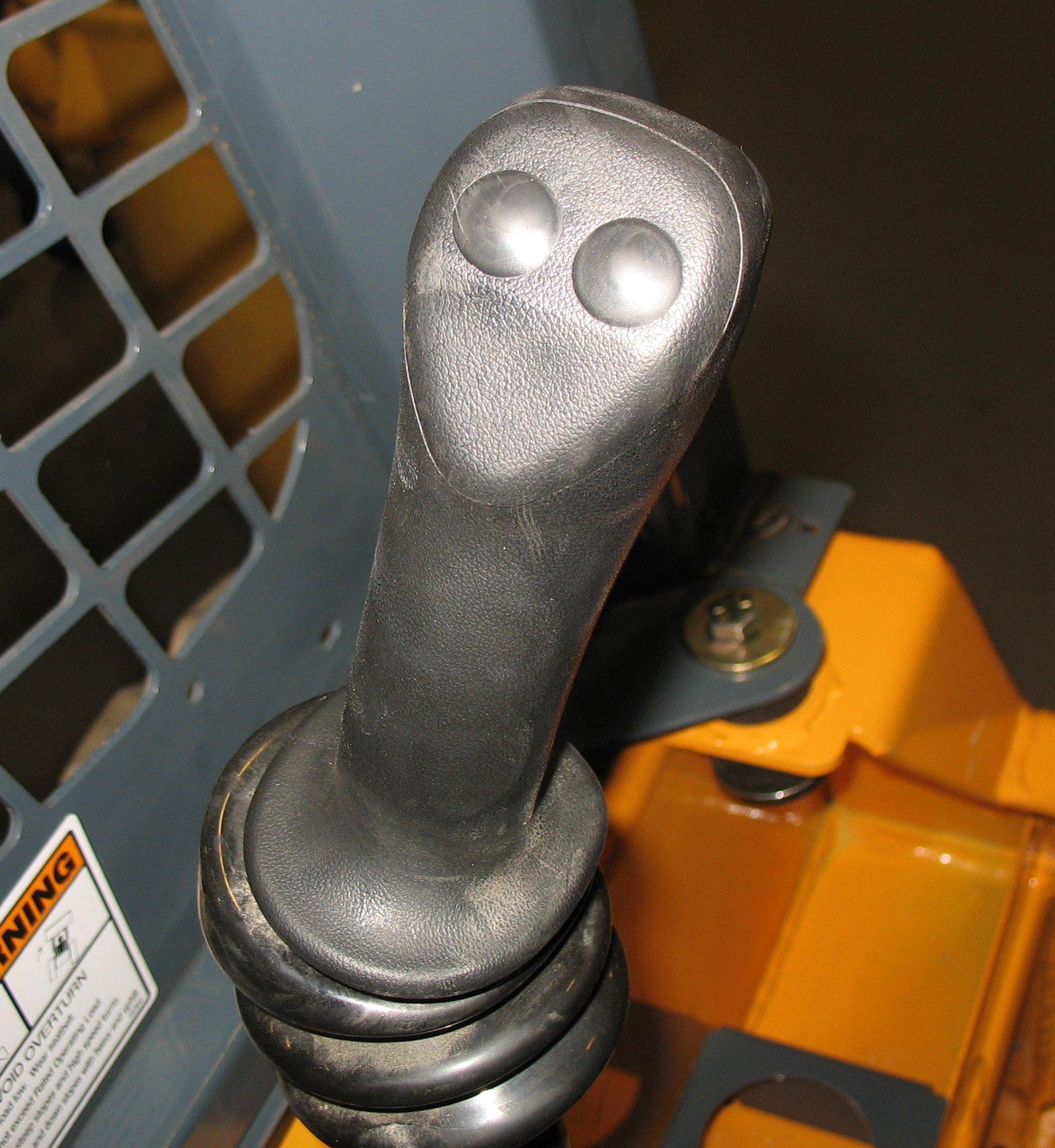
Joystick Controls
On joystick-equipped machines, the left joystick controls the travel drive, and the right joystick controls the attachment lift and tilt.
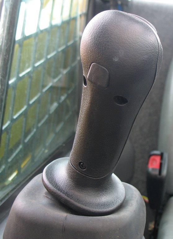


Left Joystick Right Joystick
Controls
Table 9: Joystick Controls
Ref. Control Description
ALeft Joystick
BRight Joystick
CTwo-Speed Selection Button
Controls drive forward, reverse, turn, and speed. See “Drive Control (Left Joystick)” on page63.
Controls lift arm raise/lower, float, and attachment tilt. See “Lift/Tilt Control (Right Joystick)” on page63.
Toggles between high- and low-speed travel modes. See “Two-Speed Drive” on page67.
DHorn Button Activates horn.
EHydraglide™ Button
FFloat Button
G Auxiliary Hydraulics Rocker Switch
H Auxiliary Hydraulics Continuous Flow Latch Trigger
Activates Hydraglide™. See “Hydraglide™ Ride Control System (Option)” on page71.
Activates Float. See “Lift Arm Float” on page69.
Controls auxiliary hydraulics flow direction and amount. See “Auxiliary Hydraulic System” on page78.
Works with Auxiliary Hydraulics Rocker Switch to latch/ unlatch auxiliary hydraulics continuous flow. See “Auxiliary Hydraulic System” on page78.
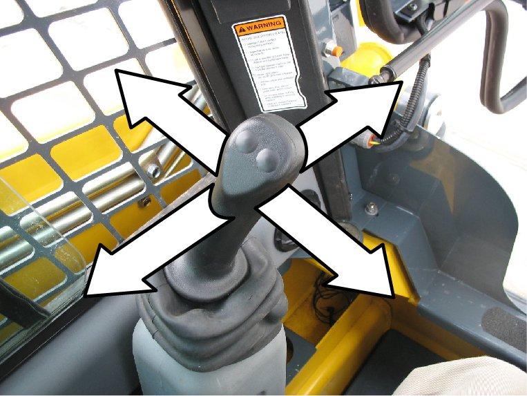
Drive Control (Left Joystick)
Forward, reverse, travel speed and turning maneuvers are controlled using the left joystick (Figure 28):
A.To go forward, push the left joystick forward.
B.To go in reverse, pull the left joystick rearward.
C.To turn right, push the left joystick to the right.
D.To turn left, push the left joystick to the left.
E.To go forward and to the right, push the left joystick forward and to the right.
F.To go rearward and to the right, pull the left joystick rearward and to the right.
G.To go forward and to the left, push the left joystick forward and to the left.
H.To go rearward and to the left, pull the left joystick rearward and to the left.
Warning
Be sure the joystick controls are in neutral before starting the engine. Operate the controls gradually and smoothly. Excessive speed and quick control movements without regard for conditions and circumstances are hazardous and could result in loss of control and cause an accident.
Moving the joystick farther from neutral increases the speed steadily to the maximum travel speed. Tractive effort decreases as speed increases. For maximum tractive effort, move the joystick only slightly away from the neutral position. The engine may stall if the control is moved too far forward when loading the bucket.
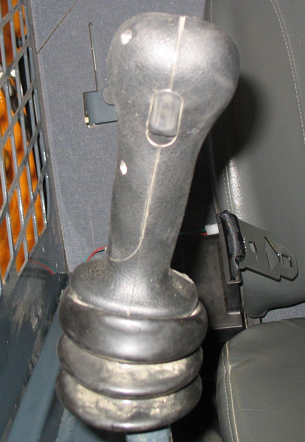
Lift/Tilt Control (Right Joystick)
Lift arm raise and lower, and attachment tilt are controlled using the right joystick (Figure 29):
A.To lower the lift arm, push the right joystick straight forward.

B.To raise the lift arm, pull the right joystick straight back.
C.To tilt the attachment forward and down, move the right joystick to the right.
D.To tilt the attachment up and back, move the right joystick to the left.
E.To lower the lift arm while tilting the attachment forward and down, move the right joystick forward and to the right.
F.To lower the lift arm while tilting the attachment up and back, move the right joystick forward and to the left.
G.To raise the lift arm while tilting the attachment forward and down move the right joystick rearward and to the right.
H.To raise the lift arm while tilting the attachment up and back, move the right joystick rearward and to the left.
Note: The speed of the lift/tilt motion is directly proportional to the amount of joystick movement and engine speed.
Hand and Foot Controls


On hand and foot controlled-equipped machines, the hand controls are used to control the travel drive, and the foot controls are used to control the attachment lift and tilt.
Left Hand Control
Right Hand Control
Foot Controls
Controls
Table 10: Hand and Foot Controls
Ref. Control Description
ALeft Hand Control
Controls travel drive forward, reverse, turn, and speed. See “Drive Control (Hand Controls)” on page66.
BRight Hand Control Controls travel drive forward, reverse, turn, and speed. See “Drive Control (Hand Controls)” on page66.
CTwo-Speed Selection Button
Toggles between high- and low-speed travel modes. See “Two-Speed Drive” on page67.
DHorn Button Activates horn.
EHydraglide™ Button
FINACTIVE
Activates Hydraglide™. See “Hydraglide™ Ride Control System (Option)” on page71.
Button is inactive on Hand and Foot Controls.