5 minute read
Diesel Particulate Filter (DPF) Regeneration Procedures (DPF Models)

from Gehl RT165 RT165 (EU) RT165 X-Series Compact Track Loader Operator’s Manual 50950264 - PDF DOWNLOAD

The Diesel Particulate Filter (DPF) treats exhaust emissions in compliance with Tier 4 emission standards. The DPF filter relies on high exhaust temperatures. Periodic DPF maintenance (regeneration) is required, dependent upon machine operation load / temperature.
Note: Machines operated primarily at high loads and operating temperatures require less frequent DPF maintenance. Extended periods of engine idling rapidly increases DPF soot levels, requiring more frequent regeneration operations.
There are 3 modes of DPF regeneration:
• Passive / Assist Regeneration: Occurs automatically without operator input. Passive/ assist regeneration does not affect machine operation.
• Reset Regeneration: Occurs automatically, but can be inhibited by the operator. Increases exhaust gas temperatures. Reset regeneration occurs approximately every 100 hours of operation. See “Reset Regeneration” on page 119.
Note: Reset regeneration effectiveness is improved if the machine is operated at mid- to high-throttle settings when reset regeneration mode is in progress.
• Stationary Regeneration: Requires operator action to initiate and takes approximately 25-30 minutes to complete. See “Stationary Regeneration” on page 120.
Important: The machine cannot be operated and must be parked in a well-ventilated area away from flammable materials when stationary regeneration is in progress.
There is a possibility of carbon monoxide poisoning if stationary regeneration occurs in an enclosed space. Always perform stationary regeneration in a wellventilated area.
During regeneration, there will be high exhaust gas temperatures, even at low load. Stay clear of the DPF during regeneration.
Reset Regeneration
Important: Reset regeneration can be prevented from occurring. See “Reset Regeneration Inhibit” on page 119.
Reset regeneration occurs automatically (unless inhibited) approximately every 100 hours of operation.
Note: Reset regeneration effectiveness is improved if the machine is operated at mid- to high-throttle settings while regeneration is in progress.
When reset regeneration occurs, the DPF inprogress (elevated temperature) symbol (K, Figure 78) displays on the screen.
1234.5
Reset Regeneration Inhibit
DPF regeneration inhibit prevents reset regeneration from occurring.
Caution
Permanently inhibiting regeneration is not recommended, as this will eventually cause significant reduction in engine power and will force premature DPF soot filter replacement.
To temporarily inhibit reset regeneration, hold down button (U, Figure 79) until the strikethrough in the Reset Regeneration symbol (W) turns to red.
Note: DPF in-progress (elevated temperature) symbol (K, Figure 78) will not be displayed when reset regeneration is inhibited.
Stationary Regeneration
Stationary regeneration may be periodically required to reduce DPF soot build-up. The frequency of stationary regeneration is dependent upon machine operation and engine load.
The machine cannot be used during stationary regeneration and cannot be moved without interrupting the stationary regeneration process.
When stationary regeneration needs to be performed, the regeneration request screen (Figure 80) displays on the information center electronic display.
Note: The stationary regeneration request screen can be temporarily dismissed by pressing the reset regeneration inhibit button (U, Figure 79 ) for 3 seconds. Until the previous screen displays. The stationary regeneration request screen will return 1 minute after being dismissed, for as long as the request remains active.
Important: Perform stationary regeneration as soon as possible when the stationary regeneration request screen displays. Postponing stationary regeneration for extended periods will cause significant reduction in engine power and will force premature DPF filter core replacement.
To proceed with stationary regeneration (Figure 81):
1. Park the machine in a safe, well-ventilated location away from flammable materials.
2. The following conditions need to be met before stationary regeneration continues:
A. Press the button on the control keypad (page 48) or lift the operator restraint bar to apply the parking brake. A checkmark is displayed next to the parking brake symbol (A).
B. When engine coolant has reached operating temperature (above 140° F / 60° C, a checkmark is displayed next to the coolant temperature symbol (B).
C. Place throttle controls to the lowest speed setting. A checkmark is displayed next to the engine RPM symbol when the engine is running at low idle.
3. When all three checkmarks (A, B & C) are displayed on the Stationary Regeneration screen, press and hold the button (Z) until the Stationary Regeneration In-Progress screen displays (Figure 82).
Note: Stationary regeneration can be interrupted at any time by releasing the parking brake, advancing the throttle, or stopping the engine. Stationary regeneration must start again from the beginning if it is interrupted.
22 %
Stationary regeneration completion percentage is displayed as during the stationary regeneration progresses. Progress percentage disappears when stationary regeneration completes.
Note: Stationary regeneration takes approximately 25-30 minutes.
It is not necessary to stay in the machine during stationary regeneration. Keep the machine under observation while regeneration is in progress in case of malfunction. Keep bystanders away from the machine while regeneration is in progress.
Forcing Stationary Regeneration
Stationary regeneration can be performed at any time after 50 operating hours following the previous stationary regeneration.
To perform stationary regeneration ondemand:
Press button (Y, Figure 83) associated with the DPF regeneration symbol (X), until the regeneration screen displays. Refer to “Stationary Regeneration” on page 120 to proceed with stationary regeneration.
DPF Maintenance
DPF soot filter replacement is required when the DPF (Diesel Particulate Filter) Service Screen (Figure 84) displays.
Note: Contact your dealer when the DPF Service screen displays.
Camera Observation System
A camera observation system is optionally available on all models. The camera observation system utilizes a rear-facing camera mounted within the rear door of the machine to provide full visibility to the region behind the machine of which portions of that region may otherwise be masked by the machine’s structure. The camera system is configured to turn on automatically when the machine’s ignition switch is moved to the “ON” position. The camera image is displayed on the monitor which is centered above the front door opening of the operator’s compartment. The vertical viewing angle of the monitor is adjustable by loosening the knobs positioned on either side of the monitor. Prior to operating the machine the operator should check the monitor to verify that the monitor is positioned at the optimum viewing angle for them.
As an integral safety feature of the machine it is important for the operator to verify that the camera system is operating properly prior to moving the machine. A camera system that is operating properly will display a sharp image that is free of any obstructions when the key is switched on. The displayed image should be centered on the area directly behind the machine. If the displayed image does not meet this criteria the following system checks can be made:
• While the system is configured to power up automatically upon key on, depress the system power button at the display to see if the system powers up.
• Verify that the electrical connections to the monitor and camera are intact. This includes checking the A/V cable connection into the rear of the monitor and the camera connection to the camera extension cable located in the engine compartment in close proximity to the rear door hinges.
• Roll back the ROPS/FOPS and check the camera system harness connections forward of the engine flywheel housing. The connection of the camera system power harness to the accessory power connections in the chassis harness are located in this region. Verify that these connections are intact.
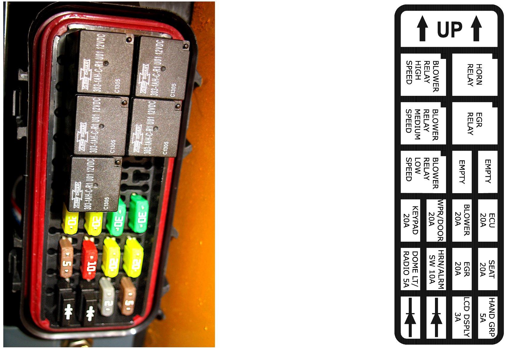
• Remove the right A-pillar cover within the ROPS/FOPS and locate the fuse holder in the camera system power harness located therein. Verify that the two Amp fuse within is intact and fully inserted into the fuse holder terminals.
• If the monitor displays a picture but that picture is not bright and clear, verify that the camera lens is clean and that the camera is properly aligned with the aperture in the rear door. The mounting brackets allow for left/right, up/down, and fore/aft adjustment. When making adjustments, ensure that the resulting pictures displayed on the monitor squarely shows the area behind the loader.
Additional troubleshooting measures are detailed in the camera observation system manual for instructions on how to correct any issues.
If the camera system is not able to be made functional after these initial checks, contact your dealer for service. A camera system that is unable to provide a clear image of the rear of the machine should be considered disabled and the machine should not be operated until the camera is made to function properly again.