DISASSEMBLE AND ASSEMBLE ENGINE GENERALLY
50 DISASSEMBLY AND ASSEMBLY
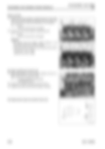
Rocker housing 103. Tighten the rocker housing (1) with the bolt (2) in the order
of [1], [2], [3], [4], [5], [6], [7], [8], [9], [10], [11], [12], [13], [14], [15], [16], [17], [18], and [19] shown in the drawing. 3 Bolt (2): 27.0 to 34.0 Nm {2.8 to 3.5 kgfm}
104. Install the nut (4) of the injector wiring harness (3).
3 Nut (4): 2.0 to 2.4 Nm {0.20 to 0.24 kgfm}
REMARK • Be careful that the injector wiring harness is not pinched by the tool and rocker housing. • Mounting positions based on the wiring harness (Color) Cylinder No.1 and 3: White Cylinder No.2 and 4: Black
Air intake manifold and common rail 105. Apply liquid gasket to the mounting surfaces of the air in-
take manifold (5) and cylinder head.
2 Air intake manifold mounting face: Liquid gasket (LG-7) 106. Install the air intake manifold (5) with the bolt (4). 107. Install the common rail (3) with the bolts (1) and (2).
Fuel high-pressure pipe and cylinder head cover
50-68
95LE-7 SERIES


