1 minute read
DISASSEMBLE AND ASSEMBLE ENGINE GENERALLY


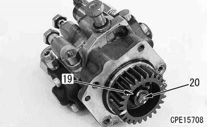
Supply pump assembly
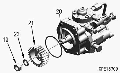
69. Install the gear (21), washer (23), and nut (19) to the shaft (20).
70. Tighten the nut (19).
3 Nut (19):
58.8 to 68.6 Nm {6.0 to 7.0 kgfm}
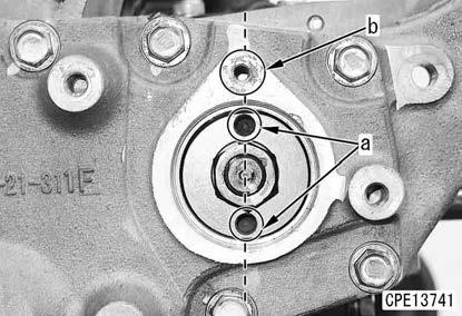
71. Align the supply pump assembly and gear (21) with the mounting positions according to the following procedure.
1) Match the top positions of the engine pistons #1 and #4.
2) Install it with the stamp mark “C” (c) of the gear facing the idler pulley.
3) When installing the supply pump assembly to the front cover, align straightly the tapped hole (a) of the gear with the tapped hole (b) of the front cover viewed from the engine front.

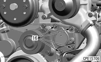
73. Install the bolts (16) (4 pieces).
DISASSEMBLE AND ASSEMBLE ENGINE GENERALLY
74. Install the bracket (16b) with the bolts (16a) (2 pieces).
Assembling the cylinder head assembly
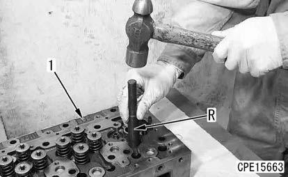
75. By using the guide screwdriver (R), install the valve guide (2) to the cylinder head (1).
Remark
Perform this work if the valve guide (2) was removed.
76. Install the valve spring seat (3).
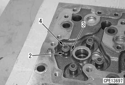

77. By using the seal screwdriver (S), install the valve seal (4) to the valve guide head.