3 minute read
FORMING OF CONDENSED WATER AND EMULSION IN KCCV SYSTEM


A: Inside of KCCV piping
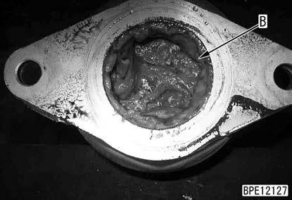
B: Inside of breather
1: Air cleaner
2: Variable flow turbocharger
3: Aftercooler
4: Engine
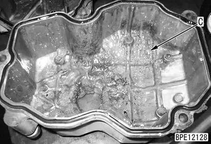
C: Back of head cover
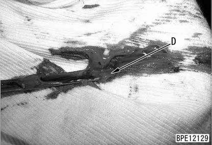
D: Level gauge
5: Breather
6: KCCV ventilator
7: Engine oil pan
Outline of the forming of condensed water and emulsion in KCCV system
•If low-load operation is continued while the ambient temperature is low, moisture in the blowby gas does not evaporate but condenses, and is returned to the engine oil pan (7) through KCCV ventilator (6). The flow of this phenomenon is as follows;
1. Moisture in blowby gas condenses in KCCV piping (A).
2. The condensed water flows into the engine oil pan (7) through the drain circuit.
3. The water evaporates in the engine oil pan (7).
4. When the water vapor condenses again inside the engine where the temperature is relative low, it is mixed with oil and whitish sediment is produced. This sediment is called mayonnaise sludge (*1).
5. If the temperature of various parts does not increase because of light-load operation, mayonnaise sludge (*1) is accumulated.
•Mayonnaise sludge (*1) is generated inside the breather (B), on the back of head cover (C), on the level gauge (D), etc. where the temperature is low and water condenses.
•Mayonnaise sludge (*1) is eliminated when loaded operation is continued and the engine oil temperature increases.
•Mixing of water condensed from the blowby gas into the oil is of no problem. But the cause of coolant leakage must be removed if the engine coolant is mixed in.
*1: Emulsion which is made from oil and water and looks like mayonnaise
Operation Of Kccv System
The left drawing shows the conventional flow of blowby gas. The right drawing shows the flow of blowby gas which is sucked in KCCV ventilator and recirculated.
A: Blowby gas
B: Clean gas
1: Air cleaner
2: Variable flow turbocharger
3: Aftercooler
4: Cylinder block (crankcase)
C: Engine oil
5: Breather
6: KCCV ventilator
7: Engine oil pan
1. This system removes engine oil (C) from blowby gas (A) in cylinder block (4) by using the filter in KCCV ventilator (6), and recirculate the clean gas (B) to the air intake side of variable flow turbocharger (2).
2. Separated engine oil (C) is drained through the check valve to engine oil pan (7).
Kccv Ventilator
KCCV
Abbreviation for KOMATSU Closed Crankcase Ventilation STRUCTURE
Of Kccv Ventilator
REMARK
The shape is subject to machine models. General view and sectional view
A: Blowby gas inlet (from breather)
B: Blowby gas outlet (to variable flow turbocharger intake side)
1: Case
2: Filter
Function Of Kccv Ventilator
C: Oil drain port (to oil pan)
3: CDR valve
4: Relief valve
•If the blowby gas is returned to the intake side of variable flow turbocharger and crank case pressure becomes negative, the dust may be sucked in through crank seal. CDR valve (3) controls the pressure inside the crankcase to prevent this to occur
•Crankcase pressure may increase and oil leakage may occur if filter (2) of KCCV ventilator is clogged. Thus, crankcase pressure sensor detects the clogging of filter (2).
•Filter is classified by the working direction for filter replacement into 2 types; the top load type (removed upward) and bottom load type (removed downward).
Operation Of Kccv Ventilator
1. When blowby gas enters blowby gas inlet (A) and passes through filter (2), engine oil mist is separated.
2. The separated oil flows on the wall surface of case (1) to oil drain port (C), and it flows to the engine oil pan.
3. The crankcase pressure sensor detects the pressure in the crankcase (blowby gas pressure). If the engine controller detects filter clogging by detected value of crankcase pressure sensor, it displays failure code CA555. If the pressure increases further, it displays failure code CA556.
4. Relief valve (4) is installed in case (1) and operates when filter (2) is blocked.
5. When the pressure in the crankcase becomes negative, CDR valve (3) operates to prevent the pressure in the crankcase from becoming excessively negative.
Cdr Valve
CDR
Abbreviation for Crankcase Depression Regulator
Operation Of Cdr Valve
1. Spring (2) normally pushes up diaphragm (1), and the blowby gas flows from crankcase side (A) into turbocharger side (air intake side) (B).
2. As the intake air at turbochaeger side (air intake side) (B) increases, pressure on crankcase side (P1) decreases.
3. The reaction force of spring (2) is overwhelmed by ambient pressure (P2). Diaphragm (1) shuts the passage and temporarily blocks the flow.
4. When the blowby gas accumulates in the crankcase, pressure (P1) on the crankcase side increases, and it pushes up diaphragm (1) again and blowby gas starts to flow.