1 minute read
DISASSEMBLE AND ASSEMBLE ENGINE GENERALLY


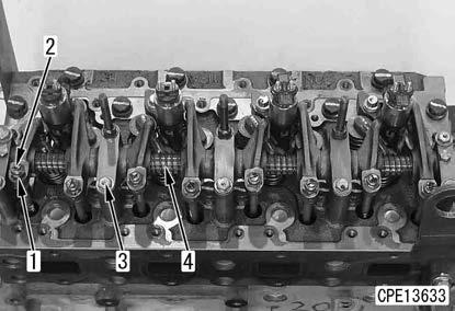
Rocker arm assembly
83. Loosen the lock nuts (1) (8 pieces) and fully loosen the adjustment screws (2) (8 pieces).
84. Remove the bolts (3) (10 pieces), and remove the rocker arm assembly (4).
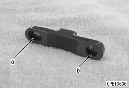
Push rod and crosshead
85. Remove the push rods (1) (8 pieces).
86. Remove the crossheads (2) (8 pieces).
REMARK
Record the mounting positions and hole shapes of the portions (a) and (b). (To assemble them correctly in the same direction again)
Injector assembly
87. Remove the bolts (1) (4 pieces), and remove the injector holders (2) (4 pieces).
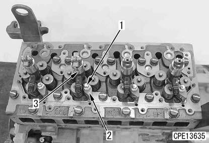
Remark
Do not reuse the bolts. Replace them with new ones.
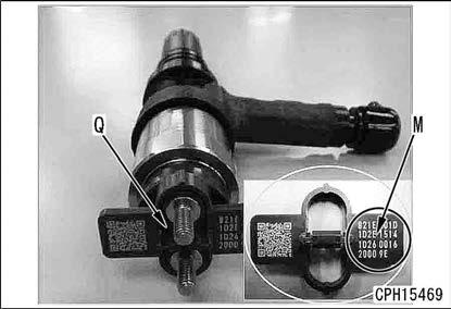
88. Record No. of the cylinder to which the injector is installed and the character string (M) listed on QR code tab (Q) as a set.
REMARK
•Check that the recorded character string (M) is correct.
•Read the character string (M) in the order indicated by the arrow in the figure.
89. Remove the injectors (3) (4 pieces).
REMARK
•Do not remove QR code tab (Q) attached to the injector head.
•Do not scratch QR code tab (Q) attached to the injector head.
(The QR code or character string indicates the compensation value for fuel injection of the injector, which is specific to each injector.)
Cylinder head assembly
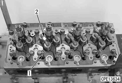
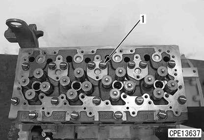
90. Remove the bolts (1) (17 pieces).
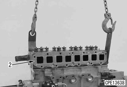
91. Sling the cylinder head assembly (2), and remove it.
4 Cylinder head assembly (2): 35 kg
REMARK
Spread a cloth, etc. to prevent the cylinder head assembly mounting part from being damaged, and place the assembly on the cloth.