2 minute read
DISASSEMBLE AND ASSEMBLE ENGINE GENERALLY


Preparation
1. Set the engine assembly (1) on the block (A).
REMARK
The weight of the engine assembly (1) may vary depending on the mounted machine model.
4 Engine assembly (1) :

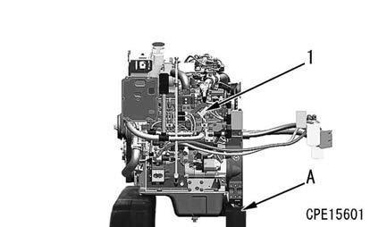
430 kg
2. Drain the engine oil.
REMARK
The oil level may vary depending on the mounted machine model.
6 Engine oil:
11.5 ℓ
Engine controller assembly, fuel filter assembly, and engine oil filter assembly
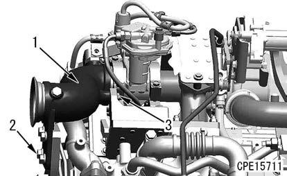
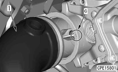
3. Remove the engine controller assembly (1).
NOTICE
Put the masking on each connector part of the engine controller assembly.
4. Remove the fuel filter assembly (2) together with the hose as a unit.
5. Remove the engine oil filter assembly (3) together with the hose as a unit.
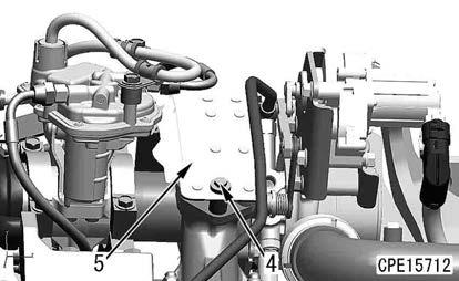
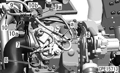
Exhaust throttle valve
6. Remove the bolts (2) (4 pieces) and bolt (3) (1 piece) of the exhaust pipe (1).
7. Remove the bolts (3 pieces), and remove the cover (5).
8. Remove the sleeve nuts (6) and (7).
NOTICE
Hold the parts (a) and (b) with a wrench, etc. to remove them.
9. Remove the clamp (8).
10. Remove the clamp (9), disconnect the connector ETV (10), and remove the connector from the connector board.
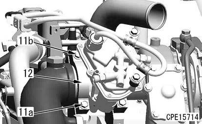
11. Remove the bolts (11a) and (11b), and remove the clamp (12).
Remark
Put matchmarks so that you can find the mounting direction (vertical) of the clamp (12).
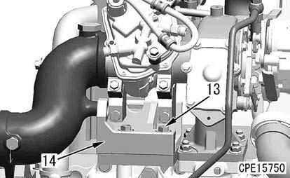
12. Remove the bolts (13) (2 pieces), and remove the bracket (14).
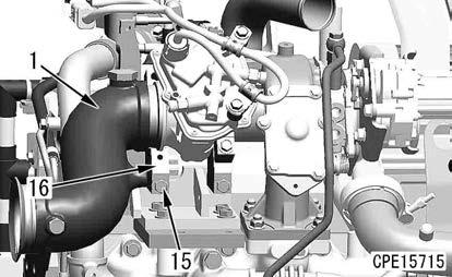
13. Remove the bolt (15), and remove the lower clamp (16).
REMARK
When removing the clamp (16), support the exhaust pipe (1).
14. Remove the exhaust pipe (1).
NOTICE
A pin is provided at the installing part (c) of the exhaust pipe (1). Remove the exhaust pipe (1) horizontally to the pin.
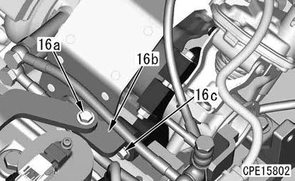
15. Remove the bolts (16a) and (16c), and remove the bracket (16b).
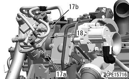
16. Remove the bolts (17a) and (17b), and remove the clamp (18).
Remark
Put matchmarks so that you can find the mounting direction (vertical) of the clamp (18).
17. Remove the bolt (19), and remove the lower clamp (20).
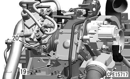
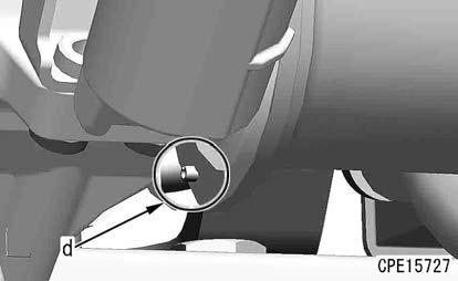
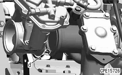
18. Remove the exhaust throttle valve (21).
Notice
A pin is provided at the installing part (d) on the turbocharger side. Remove the exhaust throttle valve (21) horizontally to the pin.
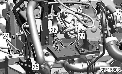
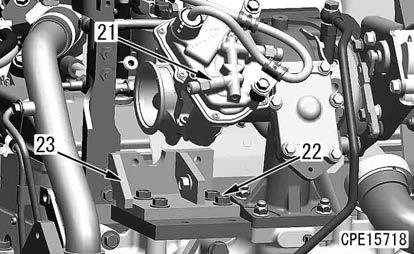
19. Remove the bolt (22), and remove the bracket (23).
20. Remove the bolts (24) (2 pieces), and remove the bracket (25).
21. Remove the bolts (26) (3 pieces), and remove the bracket (27).
k Install the wrench to the part (a) of the auto-tensioner (2) securely, and then rotate it. (The spring of the auto-tensioner (2) is strong. If the wrench is loosely installed and rotated, it can accidentally come off and this is extremely dangerous.)
k After removing the fan belt (1), slowly and carefully restore the auto-tensioner (2).
k Be careful not to get your fingers caught between the pulley and fan belt (1) during work.
k Remove the fan belt under the mounting condition if required by referring to DISASSEMBLY AND ASSEMBLY in the shop manual for the mounted machine model.
22. Insert a wrench in the part (a) (width across flats: 12.7 mm) of the tensioner assembly (2), and rotate it in the direction of the arrow (b) to weaken the fan belt tension.
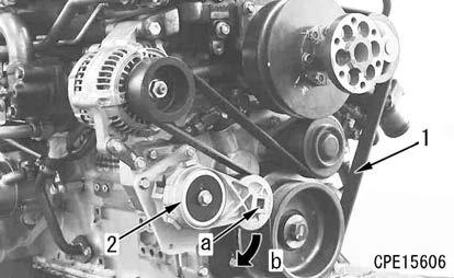
23. Remove the fan belt (1).
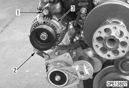
Alternator assembly
24. Remove the bolts (1) and (2), and remove the alternator (3).
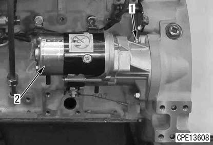
Starting motor assembly
25. Remove the bolts (1) (2 pieces), and remove the starting motor (2).