3 minute read
DISASSEMBLE AND ASSEMBLE ENGINE GENERALLY


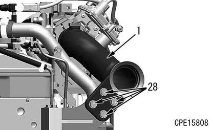
178. Tighten the bolts (28) (4 pieces) of the exhaust pipe (1) lightly.
179. Tighten the bolt (15) of the lower clamp (16) to the specified torque.
3 Bolt (15):
59 to 74 Nm {6.0 to 7.5 kgfm}
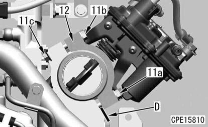
180. Loosen the bolts (11b) and (11a), insert the plate (D) into the clearance on the bottom side of the clamp (12), and tighten the bolt (11a) lightly.
181. Tighten the bolt (11b) and nut (11c) to the specified torque.
3 Bolt (11b):
14 Nm {1.5 kgfm}
182. Remove the plate (D), and tighten the bolt (11a) to the specified torque.
3 Bolt (11a):
14 Nm {1.5 kgfm}
183. Retighten the bolts (11b) and (11a).
3 Bolts (11b),(11a):
27 to 34 Nm {2.8 to 3.5 kgfm}
184. Tighten the bracket (14) lightly with the bolts (3) and (13).
185. Tighten the bolts (28), (3) and (13) to the specified torque.

3 Bolt (28):
59 to 74 Nm {6.0 to 7.5 kgfm}
3 Bolt (3):
27 to 34 Nm {2.8 to 3.5 kgfm}
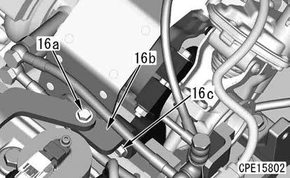
186. Tighten the bracket (16b) lightly with the bolts (16a) and (16c).
187. Tighten the bolts (16a) and (16c) of the bracket (16b) to the specified torque.
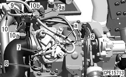
188. Install the sleeve nuts (6) and (7) of the hose.
Notice
Hold the parts (a) and (b) with a wrench, etc. to install them.
189. Install the hose clamp (8).
190. Install the connector ETV (10) to the connector board.
191. Install the cover bracket (10b) and wiring harness clamp (9) with the bolt (10a).
Remark
The bolt (10a) is tightened together with the cover bracket (10b) and wiring harness clamp (9).
192. Install the wiring harness clamp (9a).
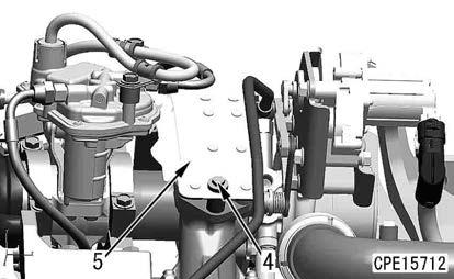
193. Install the cover (5) with the bolts (4) (3 pieces).
When the exhaust throttle valve is replaced with a new one
194. When the exhaust throttle valve is replaced with a new one, reset the total number of exhaust throttle valve strokes. For details, see TESTING AND ADJUSTING, “Testing menu (Total exhaust throttle valve stroke reset)” of “SET AND OPERATE MACHINE MONITOR” in the shop manual for the mounted machine model.
Starting motor assembly
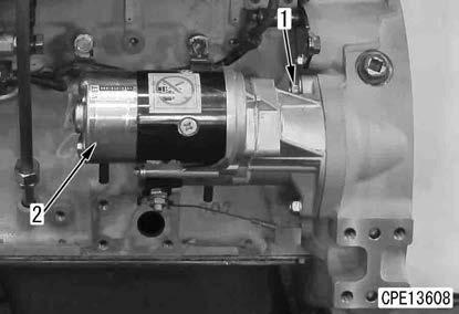
195. Install the starting motor (2) with the bolt (1).
Alternator
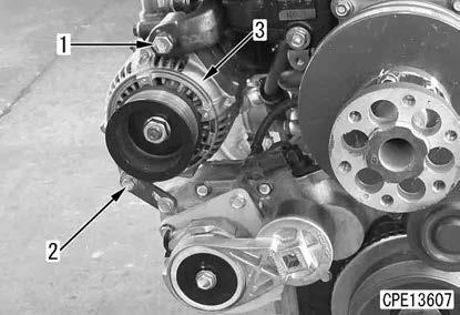
196. Install the alternator (3) with the bolts (2) and (1).
Fan belt
197. Insert a wrench in the part (a) (width across flats: 12.7 mm) of the auto-tensioner assembly (2), and install the fan belt (1) while rotating it in the direction of the arrow (b).
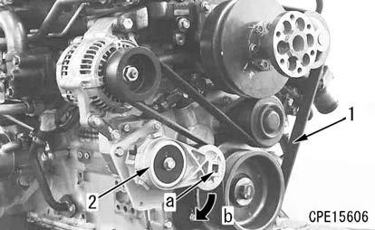
k Install the wrench to the part (a) of the auto-tensioner (2) securely, and then rotate it. (The spring of the auto-tensioner (2) is strong. If the wrench is loosely installed and rotated, it can accidentally come off and this is extremely dangerous.)
k After installing the fan belt (1), slowly and carefully restore the auto-tensioner (2).
k Be careful not to get your fingers caught between the pulley and fan belt (1) during work.
Engine controller assembly, fuel filter assembly, and engine oil filter assembly
NOTICE
If the engine controller assembly, fuel filter assembly, and engine oil filter assembly were replaced, install the engine to the machine, and then write the injector compensation value to the engine controller. For details, see TESTING AND ADJUSTING, “WRITE INJECTOR COMPENSATION VALUE TO ENGINE CONTROLLER” in the shop manual for the mounted machine model.

198. Install the engine oil filter assembly (3) together with the hose as a unit.
199. Install the fuel filter assembly (2) together with the hose as a unit.
200. Install the engine controller assembly (1).
Remove And Install Supply Pump Assembly
Tools to be used when removing and installing the supply pump assembly
G790-101-3000Push puller
■1Removal of supply pump gear
Method For Removing Supply Pump Assembly
Advance preparation
1. Rotate the crankshaft in the normal direction (clockwise viewed from the engine front) to align the notch part (a) of the plate (1) at the rear of the crankshaft pulley with the embossed mark (b) “1.4TOP” of the front cover (2) before removing.

Remark
•Perform cranking while holding the crankshaft pulley bolt (3).
•Be sure to rotate the crankshaft pulley bolt only in the normal rotation direction to prevent it from being loosened.
•Cranking can be performed depending on the machine model.
1) When the plug (c) of the flywheel housing is removed, the mark (painted in white) of the No.1 cylinder top dead center on the flywheel side can be checked.
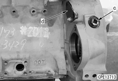
2) When the cover (d) of the flywheel housing is removed, the barring tool for cranking can be installed.
For details, see the shop manual of each model.
3) At the No.1 cylinder compression top dead center, the intake and exhaust rocker arm of the No.1 cylinder can be moved by the valve clearance with hands. If the rocker arm cannot be moved by hands, the No. 1 cylinder is not at its compression top dead center. In this case, rotate the crankshaft one more turn.
Fan belt