6 minute read
DISASSEMBLE AND ASSEMBLE ENGINE GENERALLY


Injector assembly Cylinder head cover
Crosshead, push rod
Rocker housing, rocker arm assembly
Common rail, air intake manifold Dipstick pipe
Fuel highpressure pipe
Air intake connector, intake air heater
EGR valve assembly
Thermostat housing Water pump assembly
Down from the engine repair stand to block
Engine oil cooler, adapter assembly E
Thermostat assembly E Exhaust manifold EGR cooler assembly Exhaust throttle valve
Wiring harness assembly
Fan pulley, idler pulley, tensioner assembly
Alternator assembly
Turbocharger assembly
Starting motor assembly
Fan belt
Engine controller assembly, fuel filter assembly, engine oil filter assembly
Cylinder block assembly
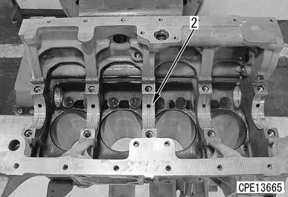
1. Install the bracket (C) to the cylinder block assembly (1).
2. Sling the cylinder block assembly (1) together with the bracket (C) as a unit, and set them to the repair stand (B).
4 Cylinder block assembly (1):

80 kg
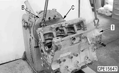
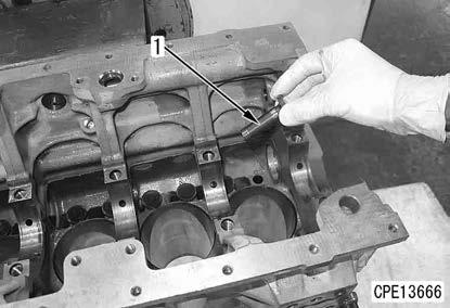
Tappet
3. Apply engine oil to the tappet (1).
2 Tappet:
Engine oil
4. Install the tappets (1) (8 pieces).
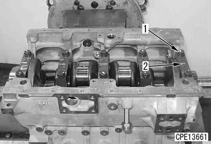
Crankshaft assembly
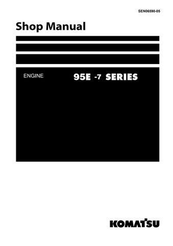
5. Install the main bearing (2).
Remark
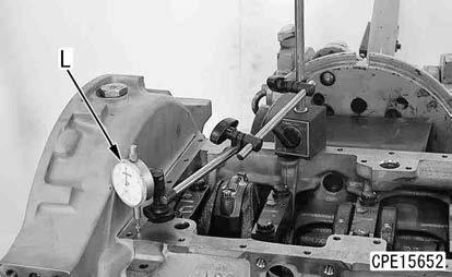
•Set the protruding portion of the main bearing to the notch of the cylinder block for installation.
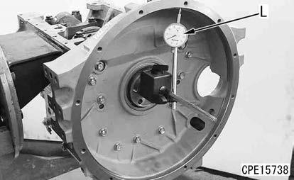
•Check that foreign material is not attached to the back surface of the main bearing before installation.
•Apply engine oil to the inner surface of the main bearing. At this time, do not apply engine oil to the back surface.
2 Inside surface of main bearing:
Engine oil
6. Install the crankshaft assembly (1) onto the main bearing while taking care not to allow the crankshaft assembly to interfere with the block.
4 Crankshaft assembly (1):
30 kg
•When the crankshaft gear was replaced Put the crank gear into the electric furnace, etc., heat it at the maximum temperature of 190 °C for approximately 30 minutes, and shrink fit the gear.
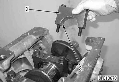
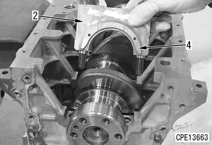
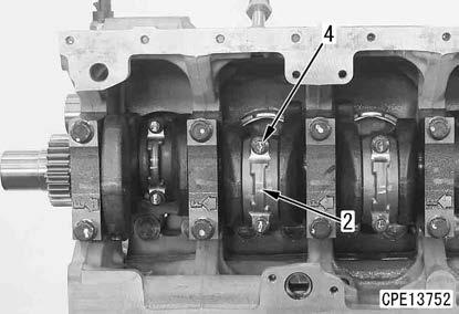
Main cap
7. Install the lower bearing (3) while aligning with the notch of the each main cap (2).
REMARK
•Check that foreign material is not attached to the back surface of the main bearing before installation.
•Apply engine oil to the inner surface of the lower bearing (3). At this time, do not apply engine oil to the back surface.
2 Inner surface of lower bearing:
Engine oil
8. Install the thrust bearing (4) to the main cap (2) while aligning the thrust bearing with the dowel pin.
REMARK
•Install the thrust bearing (4) to the both sides of the main cap (2).
•Install the thrust bearing (4) while the oil groove surface faces outward.
•Apply engine oil to the entire surface of the thrust bearing (4).
2 Thrust bearing (4):
Engine oil
9. Tighten the main cap (2) to the cylinder block with the bolt (1).
REMARK
•Bring the main cap (2) into full contact with the cylinder block before tightening it with the bolt (1).
•Check that the stamping mark of the main cap (2) is the same as that of the cylinder block.

•Install the main cap while the embossed arrow faces the front side.
•Be careful not to misalign the thrust bearing (4).
10. Tighten the main cap bolts (1) (2 pieces) alternately with a torque wrench.
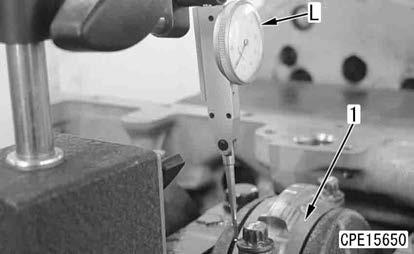
11. Place the probe of the dial gauge (L) on the end surface of the crankshaft, move the crankshaft forward and backward, and measure the end play of the crankshaft.
REMARK
•Apply engine oil to the threaded portion and seat surface of the bolt.
2 Threaded portion and seat surface of the bolt:
Engine oil
•Bolt (1)
3 1st time:
107.8 to 117.6 Nm {11.0 to 12.0 kgfm}
2nd time: Loosen the bolt completely.
3 3rd time:
127.4 to 137.2 Nm {13.0 to 14.0 kgfm}
Judgment criteria of end play: 0.131 to 0.351 mm
Assembling the piston and connecting rod assembly
12. Install the expander (2) to the oil ring (1).
REMARK
Fit the oil ring (1) so that its abutment joint is 180 ° away from the connecting portion of the expander (2). Be careful not to damage the piston or lose the ring.
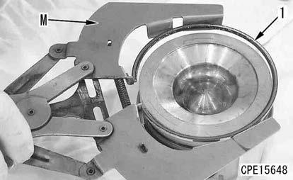
13. Install the oil ring (1) to the piston by using the piston ring tool (M).
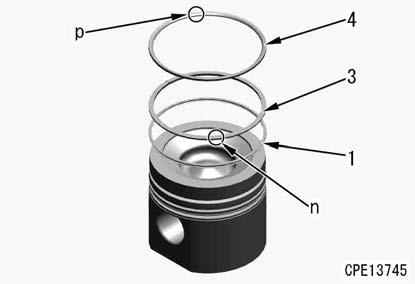
14. Install the second ring (3) to the piston by using the piston ring tool (M).
REMARK
Install the second ring so that the mark “2R” (n) close to the abutment joint faces upward.
15. Install TOP ring (4) to the piston by using the piston ring tool (M).
REMARK
Install TOP ring so that the mark “1R” (p) close to the abutment joint faces upward.
16. Set the abutment joints of the piston rings at the position shown in the figure.
FRONT: Engine front direction
(a): Oil ring abutment joint position
(b): Second ring abutment joint position
(c): TOP ring abutment joint position
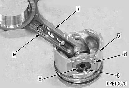
17. Install the snap ring (6) to either side of the piston (5).
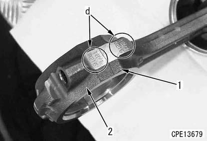
18. Insert the connecting rod (7) into the piston (5), and install the piston pin (8).
REMARK
Install the piston pin so that the embossed letter “F” (d) on each piston side surface and the embossed part number (e) on each connecting rod side surface face the engine front side.
19. Install the snap ring (6) on the opposite side.
REMARK
After installing the snap ring (6), check that the connecting rod (7) lightly moves forward and backward.
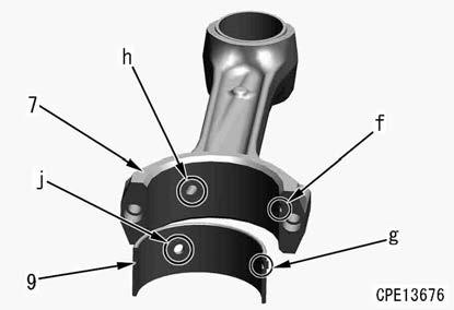
20. Install the upper connecting rod bearing (9) while aligning its projection (g) with the notch (f) of the connecting rod (7).
REMARK
•Check that no foreign material sticks on the back surface of the upper connecting rod bearing (9).
•Align the oil hole (h) of the connecting rod with the oil hole (j) of the upper connecting rod bearing.
Piston and connecting rod assembly
21. Invert the cylinder block, and set it so that the crankshaft is set vertically
22. Check the direction of the piston ring abutment joint again.
FRONT: Engine front direction
(a): Oil ring abutment joint position
(b): Second ring abutment joint position
(c): TOP ring abutment joint position
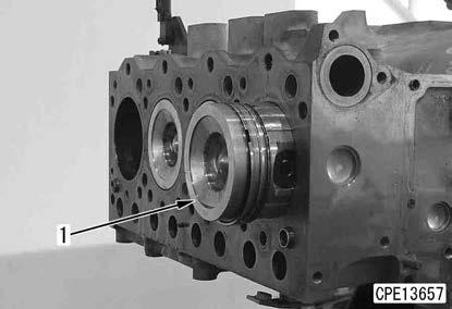
23. Set the crankshaft of the cylinder block to which the piston and connecting rod assembly (1) is installed to the bottom dead center.
24. Insert the piston and connecting rod assembly (1) into the cylinder block.
REMARK
•Insert the assembly so that the embossed letter “F” on the piston side surface faces the engine front side.
•Apply engine oil to the cylinder inner surface, piston ring, and connecting rod bearing surface.
2 Cylinder inner surface and piston ring: Engine oil
25. By using the piston holder (N), retract the piston ring, and push in the head of the piston and connecting rod assembly (1) with a wooden rod, etc.
Notice
When pushing in the piston and connecting rod assembly (1), support the large end of the connecting rod and guide it to the crankpin with hands on the opposite side to prevent from scratching. Do not push in the assembly rapidly to prevent the ring from being lost.
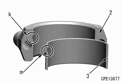
26. Install the lower connecting rod bearing (3) while aligning its projection (m) with the notch (k) of the connecting rod cap (2).
Remark
•Check that no foreign material sticks on the back surface of the lower connecting rod bearing (3).
•Apply engine oil to the inner surface of the lower connecting rod bearing (3).
2 Inner surface of the lower connecting rod bearing (3):
Engine oil
27. Install the connecting rod cap (2) to the large end of the connecting rod.
REMARK
Align the identification mark (d) of the large end of the connecting rod with that of the connecting rod cap for installation.
28. Install the connecting rod cap (2) with the bolt (4).
REMARK
•Apply engine oil to the threaded portion of the bolt (4) and the seat surface of the bolt (4).
2 Threaded portion and seat surface of the bolt (4): Engine oil
•Bolt (4)
3 1st time:
39.2 (+1.96/0) Nm {4.0 (+0.2/0) kgfm}
3 2nd time:
90 (+30/0) ° (Put matchmarks (e) to the bolt head and connecting rod seat surface, and retighten them alternately.)
29. Put 1 punch mark (f) on the head of the bolt (4).
REMARK
•Put 1 punch mark to the head of the bolt (4) every time the bolt is tightened.
•The bolt which has 5 punch marks (f) must be replaced with a new one. Do not reuse it.
•Do not put a punch mark when using a new bolt.
30. Rotate the crankshaft and check that it rotates smoothly.
31. By using the dial gauge (L), measure the end play of the piston and connecting rod assembly (1).
REMARK
Push or pull the piston and connecting rod assembly in the axial direction of the crankshaft to measure the end play. End play: 0.20 to 0.40 mm
Flywheel housing
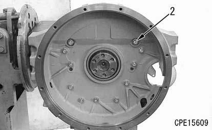
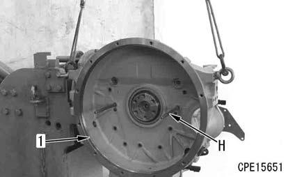
32. Install the guide bolt (H), sling the flywheel housing (1), and install it with the bolt (2).
2 Flywheel mounting face: Liquid gasket (LG-7)
3 Bolt (2):
58.8 to 73.5 Nm {6.0 to 7.5 kgfm}
33. Measure the step between the flywheel housing and cylinder block oil pan mounting surface by using the dial gauge (L).
REMARK
•Allowable limit (step on the oil pan mounting surface): Max. 0.15 mm
•If it is out of standard value, take actions by referring to “MAINTENANCE STANDARD”.
34. Measure the radial runout and facial runout of the flywheel housing by using the dial gauge (L).
REMARK
• Rotate the crankshaft to measure the radial runout and facial runout.
•If it is out of standard value, take actions by referring to “MAINTENANCE STANDARD”.
•Measurement of radial runout
Standard value: Max. 0.30 mm