2 minute read
DISASSEMBLE AND ASSEMBLE ENGINE GENERALLY


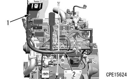
Fan pulley, idler pulley, and tensioner assembly
50. Remove the bolt (1a), and remove the clamp.
51. Remove the bolts (1) (6 pieces), and remove the fan pulley assembly (2).
52. Remove the bolts (3) (3 pieces), and remove the idler pulley assembly (4).

53. Remove the bolt (5), and remove the tensioner assembly (6).

54. Remove the bolts (7) (3 pieces), and remove the plate (8).
Bracket and wiring harness assembly
55. Remove the bracket (1).
56. Disconnect the wiring harness assembly (2).
REMARK
When disconnecting the wiring harness assembly (2), check the positions of each clamp and connector.
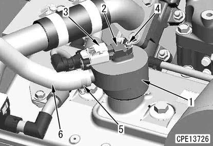
Thermostat assembly
57. Loosen the clamp (1), and disconnect the hose (2).
58. Remove the bolts (3) (4 pieces), and remove the coolant outlet connector (4).
59. Remove the thermostat (5).
60. Remove the coolant temperature sensor (6).
Disassemble And Assemble Engine Generally
Water pump assembly
61. Remove the bolts (1) (4 pieces) and bolt (2) (1 piece), and remove the water pump (3).
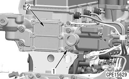

Thermostat housing
62. Remove the bolts (1) (4 pieces), and remove the thermostat housing (2).
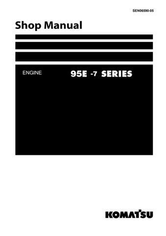
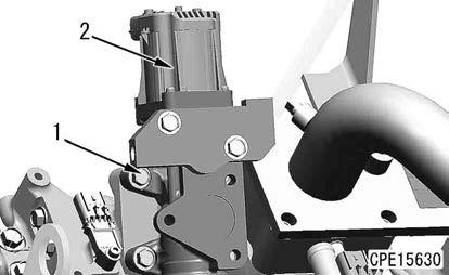
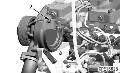
EGR valve assembly
63. Remove the bolts (1) (4 pieces), and remove EGR valve assembly (2).
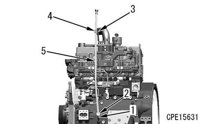
Dipstick pipe
64. Loosen the nut (2) while fixing the guide (1).
65. Remove the clamp (4) from the bracket (3), and remove the dipstick pipe (5).
Intake air heater and air intake connector
66. Remove the bolts (1) (4 pieces), and remove the tube (2) and intake air heater (3).
67. Remove the bolts (4) (4 pieces), and remove the air intake connector (5).
Fuel high-pressure pipe
Notice
When removing the fuel high-pressure pipe, be careful not to apply excessive force to the high-pressure pipe.
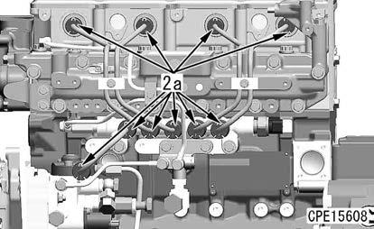
68. Remove the fuel spray prevention caps (2a) (10 pieces).
69. Remove the tube clamp (1), and remove the fuel highpressure pipe (2).
70. Remove the tube clamp (3), and remove the fuel highpressure pipe (4).
71. Remove the tube clamps (5) and (6), and remove the fuel tubes (7) and (8).
72. Remove the fuel high-pressure pipe (9) and fuel tube (10).
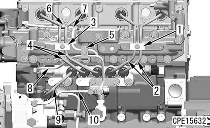
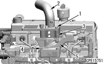
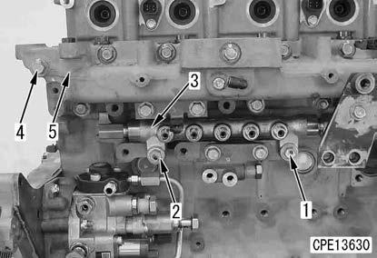
Common rail and air intake manifold
73. Remove the bolts (1) and (2), and remove the common rail (3).

74. Remove the bolts (4) (13 pieces), and remove the intake manifold (5).
Breather and cylinder head cover
75. Disconnect the connector CCV (3) from the crankcase pressure sensor (2).
76. Remove the bolt (4), and remove the crankcase pressure sensor (2).
77. Loosen the clamp (5), and disconnect the breather hose (6).
78. Remove the breather (1) from the cylinder head cover (10).
Remark
•Be careful not to remove the breather forcibly. Otherwise, O-ring may be damaged.
•Clean the peripheral area of the breather and crankcase pressure sensor (2) to prevent mud, sand, dirt, etc. from entering the engine.
79. Remove the bolts (7) (5 pieces), and remove the cover (8).
80. Remove the bolts (9) (3 pieces), and remove the cylinder head cover (10).
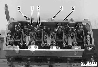
Rocker housing
81. Remove the nuts (2) (8 pieces) of the injector wiring harness (1) from the injector
Mounting positions based on the injector wiring harness (Color)
•Cylinder No.1 and 3: White
•Cylinder No.2 and 4: Black
Notice
Do not remove the injector wiring harness connectors (3) (2 pieces) from the rocker housing unless it is required.
82. Remove the bolts (4) (19 pieces), and remove the rocker housing (5).