2 minute read
REMOVE AND INSTALL SUPPLY PUMP ASSEMBLY


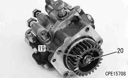
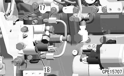
18. Remove the nut (19), washer (23), and gear (21) from the shaft (20).
Method For Installing Supply Pump Assembly
Supply pump assembly
1. Install the gear (21), washer (23), and nut (19) to the shaft (20).
2. Tighten the nut (19).
3 Nut (19): 58.8 to 68.6 Nm {6.0 to 7.0 kgfm}
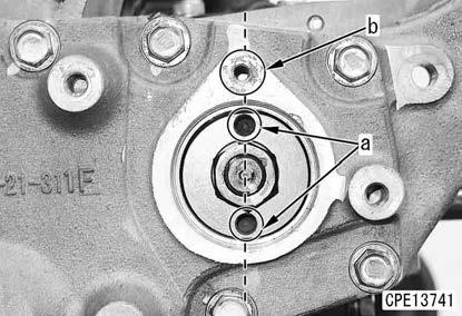
3. Align the supply pump assembly and gear (21) with the mounting positions according to the following procedure.
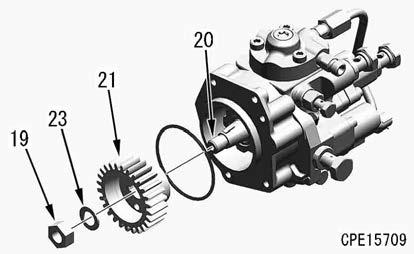
1) Match the top positions of the engine pistons #1 and #4.
2) Install it with the stamp mark “C” (c) of the gear facing the idler pulley.
3) When installing the supply pump assembly to the front cover, align straightly the tapped hole (a) of the gear with the tapped hole (b) of the front cover viewed from the engine front.

Notice
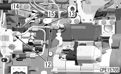
When installing the fuel high-pressure pipe (15), be careful not to apply excessive force to it.
3 Sleeve nuts (at both ends) of the fuel high-pressure pipe (15):
39.0 to 44.0 Nm {4.0 to 4.5 kgfm}
Notice
Install the fuel spray prevention cap (14) so that the slit faces downward.
Remark
The fuel spray prevention caps are installed so that fuel will not spout over the hot part of the engine when it leaks by any chance.
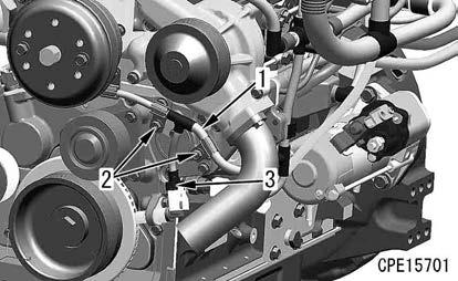
9. Install the fuel tube (13) with the joint bolts (12) (2 pieces at both ends).
10. Connect the fuel hose (10) with the joint bolt (9).
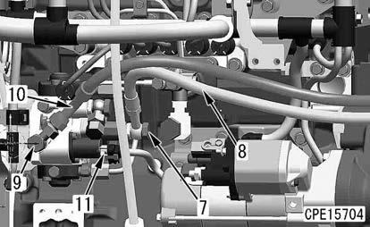
3 Joint bolt (9):
17.6 to 19.6 Nm {1.8 to 2.0 kgfm}
11. Connect the fuel hose (8) with the joint bolt (7).
3 Joint bolt (7):
17.6 to 19.6 Nm {1.8 to 2.0 kgfm}
12. Connect the connector SCV (11).
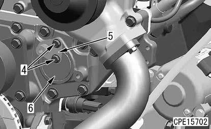
13. Install the plates (5) and (6) with the bolt (4).
3 Bolt (4):
8.8 to 14.7 Nm {0.9 to 1.5 kgfm}
14. Connect the connector NE (3) of the crankshaft speed sensor
15. Connect the wiring harness (1) with the bolt (2).
Fan belt
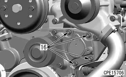
16. Insert a wrench in the part (a) (width across flats: 12.7 mm) of the auto-tensioner assembly (2), and install the fan belt (1) while rotating it in the direction of the arrow (b).
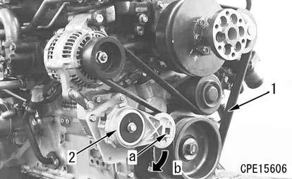
k Install the wrench to the part (a) of the auto-tensioner (2) securely, and then rotate it. (The spring of the auto-tensioner (2) is strong. If the wrench is loosely installed and rotated, it can accidentally come off and this is extremely dangerous.)
k After installing the fan belt (1), slowly and carefully restore the auto-tensioner (2).
k Be careful not to get your fingers caught between the pulley and fan belt (1) during work.
Remove And Install Engine Front Oil Seal
Tools to be used when removing and installing the engine front oil seal
Method For Removing Engine Front Oil Seal
Fan k Install the wrench to the part (a) of the auto-tensioner (2) securely, and then rotate it. (The spring of the auto-tensioner (2) is strong. If the wrench is loosely installed and rotated, it can accidentally come off and this is extremely dangerous.) k After removing the fan belt (1), slowly and carefully restore the auto-tensioner (2). k Be careful not to get your fingers caught between the pulley and fan belt (1) during work. k Remove the fan belt under the mounting condition if required by referring to DISASSEMBLY AND ASSEMBLY in the shop manual for the mounted machine model.

1. Insert a wrench in the part (a) (width across flats: 12.7 mm) of the tensioner assembly (2), and rotate it in the direction of the arrow (b) to weaken the fan belt tension.
2. Remove the fan belt (1).
3. Remove the bolt (1), and remove the idler pulley assembly (2).