3 minute read
DISASSEMBLE AND ASSEMBLE ENGINE GENERALLY


Rocker housing
103. Tighten the rocker housing (1) with the bolt (2) in the order of [1], [2], [3], [4], [5], [6], [7], [8], [9], [10], [11], [12], [13], [14], [15], [16], [17], [18], and [19] shown in the drawing.
3 Bolt (2):
27.0 to 34.0 Nm {2.8 to 3.5 kgfm}
104. Install the nut (4) of the injector wiring harness (3).
3 Nut (4):
2.0 to 2.4 Nm {0.20 to 0.24 kgfm}
REMARK
•Be careful that the injector wiring harness is not pinched by the tool and rocker housing.
•Mounting positions based on the wiring harness (Color)
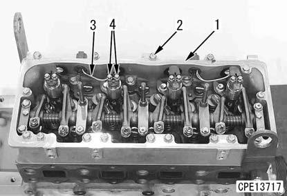
Cylinder No.1 and 3: White
Cylinder No.2 and 4: Black
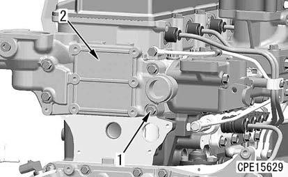
Air intake manifold and common rail
105. Apply liquid gasket to the mounting surfaces of the air intake manifold (5) and cylinder head.
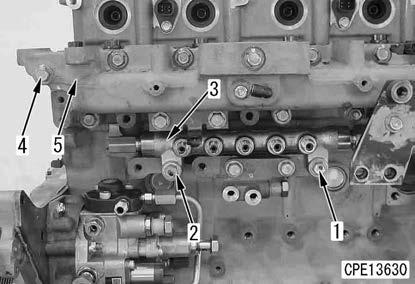
2 Air intake manifold mounting face: Liquid gasket (LG-7)
106. Install the air intake manifold (5) with the bolt (4).
107. Install the common rail (3) with the bolts (1) and (2).
Fuel high-pressure pipe and cylinder head cover k Do not bend the fuel high-pressure pipe to correct before installing. k Komatsu recommends using Komatsu genuine fuel high-pressure pipe clamps and observe the specified tightening torque. k Install each fuel high-pressure pipe and wiring harness at least 10 mm apart from each other. k Check the high-pressure pipe for the following, and install it. If the high-pressure pipe has any defect, replace it with a new one since fuel may leak. k Visually check that the taper seal part (a) of the connecting part (2 mm area from the end) is free from the longitudinal slits (b) or the spotty dents (c). k Make sure that the part (d) (the end of the taper seal: 2 mm from the end) is free from steps you can feel by your fingernails (free from fatigue).
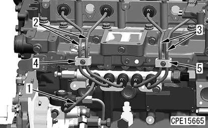
108. Install the fuel high-pressure pipe (1) to the area between the supply pump and common rail inlet.
109. Tighten the fuel high-pressure pipe (2) to the area between the common rail and No.1/No.2 injector lightly
110. Tighten the fuel high-pressure pipe (3) to the area between the common rail and No.3/No.4 injector lightly.
111.Tighten the injector holder bolt that was lightly tightened in step 93 to the specified torque.
3 Injector holder mounting bolt:
39.0 to 49.0 Nm {4.0 to 5.0 kgfm}
112. Tighten the fuel high-pressure pipe mounting sleeve nut on the injector side.
3 Mounting sleeve nut:
39.0 to 44.0 Nm {4.0 to 4.5 kgfm}
Notice
• The sleeve nut must be dry to be tightened.
•After tightening, check that O-ring is not projected.
113. Tighten the fuel high-pressure pipe mounting sleeve nut on the common rail side.
3 Mounting sleeve nut:
39.0 to 44.0 Nm {4.0 to 4.5 kgfm}
Notice
• The sleeve nut must be dry to be tightened.
•After tightening, check that O-ring is not projected.
114. Install the tube clamps (4) and (5).
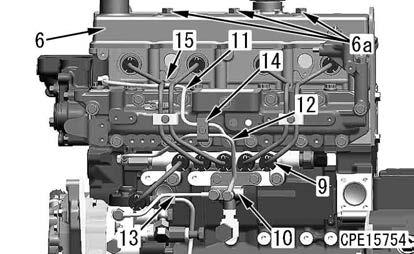
115. Install the cylinder head cover (6) with the nuts (6a) (3 pieces) to the rocker housing.

3 Nut (6a):
7.8 to 9.8 Nm {0.8 to 1.0 kgfm}
116. Install the cover (7) with the bolt (8).
3 Bolt (8):
3.6 to 4.4 Nm {0.37 to 0.45 kgfm}
117. Install the fuel spray prevention cap (9) to each sleeve nut.
REMARK
•Install the fuel spray prevention cap so that the slit faces downward.
•The fuel spray prevention caps are installed so that fuel will not spout over the high-pressure part of the engine and catch fire if it leaks by any chance.
118. Install the adapter (10), and install the fuel tubes (11), (12), and (13).
119. Install the tube clamps (14) and (15).
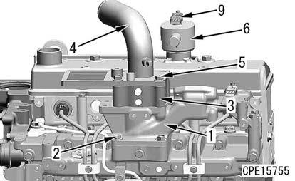
Air intake connector, intake air heater, and breather
120. Install the air intake connector (1) with the bolt (2).
121. Install the intake air heater (3) and tube (4) with the bolts (5) (4 pieces).
122. Install the breather (6) to the cylinder head cover according to the following procedure.
REMARK
•Check that O-rings (7) and (8) of the breather are not damaged or cut.
•Check that the breather mounting part is free from mud, sand, dirt, etc.
•Replace O-ring with a new one if it is damaged.
1) Apply engine oil to O-rings (7) and (8).
2 O-rings (7) and (8): Engine oil
2) Install O-rings (7) and (8) to the breather.
3) Install the breather (6) straight to the cylinder head cover assembly
REMARK
•Be careful not to install it forcibly. Otherwise, Oring may be damaged.
•Be sure to remove the crankcase pressure sensor (9) before installing the breather.
4) Tighten the crankcase pressure sensor (9) to the breather (6) with the hexagonal socket head bolt (10).
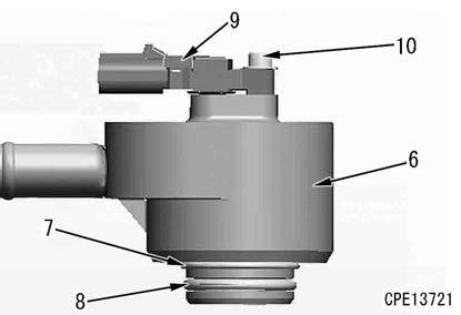
REMARK
Check that the crankcase pressure sensor mounting part is free from mud, sand, dirt, etc.
3 Hexagonal socket head bolt (10): 4.0 to 5.0 Nm {0.4 to 0.5 kgfm}
EGR valve assembly
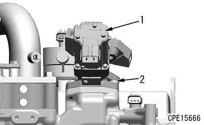
123. Install EGR valve assembly (1), and tighten it with the bolts (2) (4 pieces).
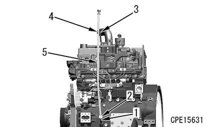
Dipstick pipe
124. Apply adhesive to the guide (1) and drive it into the cylinder block.
2 Guide (1):
Liquid adhesive (LT-2)
125. Install the dipstick pipe (5), and tighten it with the nut (2).
REMARK
When tightening the nut (2), fix the guide (1) to prevent it from rotating.
126. Install the bracket (3), and fix the dipstick pipe (5) with the clamp (4).
Thermostat housing
127. Install the thermostat housing (2), and tighten it with the bolts (1) (4 pieces).