6 minute read
DISASSEMBLE AND ASSEMBLE ENGINE GENERALLY


Disassembling the cylinder head assembly
92. Disassemble the cylinder head assembly.
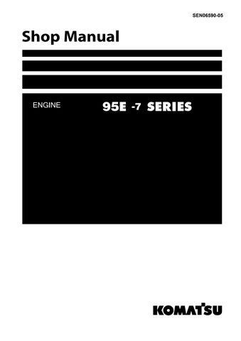
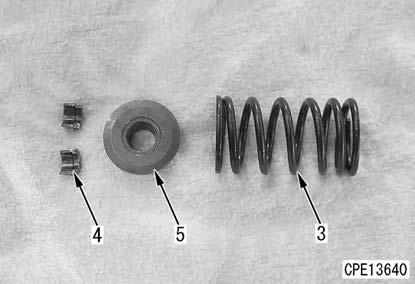
1) By using the spring pusher (E), compress the valve spring (3), and remove the cotter (4).
2) Loosen the spring pusher (E) slowly, and remove the valve spring seat (5) and valve spring (3).
REMARK
Remove these parts for all cylinders according to the same procedure.
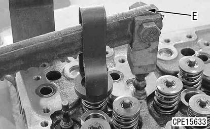
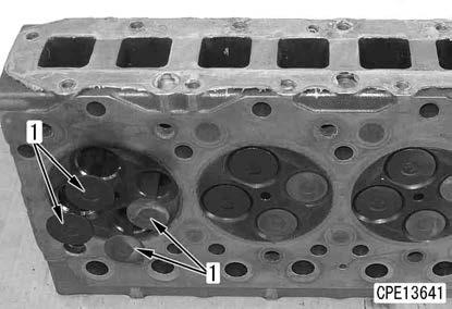
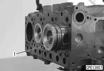
93. Turn the cylinder head assembly upward, and remove the intake and exhaust valves (1) (16 pieces).

REMARK
Put marks on the intake and exhaust valve (1) so that you can find matching cylinder head.
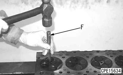
Valve guide and valve seal
94. Remove the valve seals (1) (16 pieces).
95. By using the remover (F), remove the valve guides (2) (16 pieces).
Remark
Perform this work if it is required to remove the valve guide (2).
96. Remove the valve spring seats (3) (16 pieces).
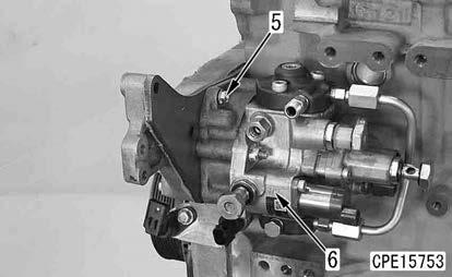
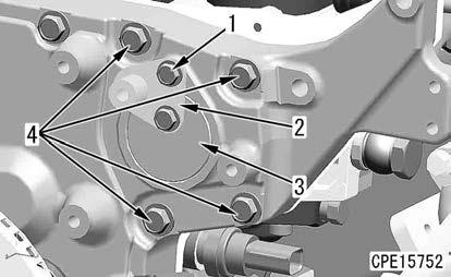
Supply pump assembly
97. Remove the bolts (1) (2 pieces), and remove the plates (2) and (3).
98. Remove the bolts (4) (4 pieces).
99. Remove the bolt (5), and remove the supply pump assembly (6).
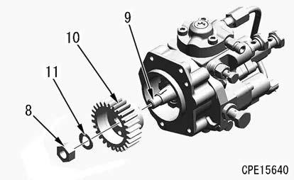
100. Remove the gear from the supply pump according to the following procedure.
1) Remove O-ring (7).
2) Loosen the nut (8).
REMARK
Do not remove the nut (8) from the shaft (9).
3) Install the push puller (G) between the flange and gear (10) of the supply pump.

4) Tighten the bolt at the center of the push puller (G) until the gear (10) comes off.
5) Remove the nut (8), washer (11), and gear (10) from the shaft (9).
Engine oil pan
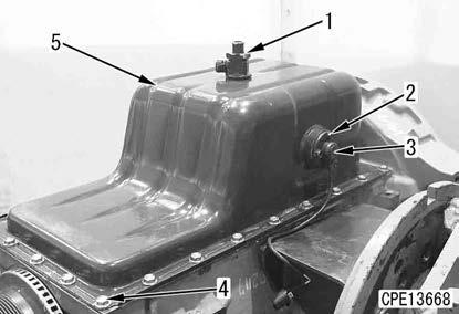
101. Rotate the engine repair stand, and direct the oil pan upward.
102. Remove the engine oil drain valve (1).
103. Remove the bolts (2) (3 pieces), and remove the engine oil level sensor (3).
104. Remove the bolts (4) (24 pieces), and remove the engine oil pan (5).
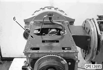
105. Remove the under plate (6) from the cylinder block.
Oil suction tube
106. Remove the bolts (1) (2 pieces), and remove the oil suction tube (2).
Crankshaft pulley
107. Remove the bolt (1).
108. Remove the plate (2).
109. Remove the crankshaft pulley (3).
Disassemble And Assemble Engine Generally
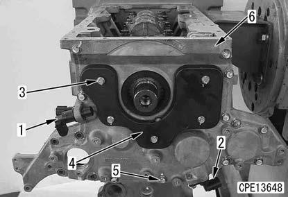
Speed sensor and front cover
110. Remove the crankshaft speed sensor (NE) (1).
111.Remove the cam speed sensor (BKUP) (2).
112. Remove the bolts (3) (5 pieces), and remove the cover (4).
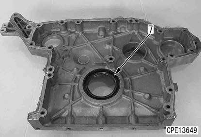
113. Remove the bolts (5) (13 pieces), and remove the front cover (6).
114. Remove the front oil seal (7).
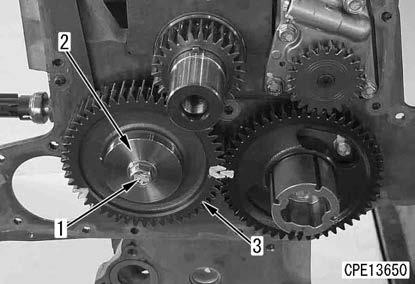
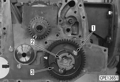
Idler gear
115. Remove the bolt (1) and washer (2), and remove the idler gear (3).
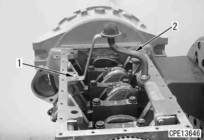
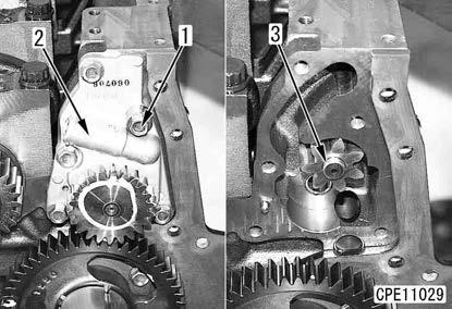
Engine oil pump assembly
116. Remove the bolts (1) (5 pieces), and remove the engine oil pump (2).
117. Remove the driven gear (3).
Camshaft assembly
118. Remove the mounting bolts (1) (2 pieces) from the molded hole of the gear.
119. Pull out the camshaft (2) together with the thrust plate (3) from the cylinder block.
Remark
Pull out the camshaft while rotating it lightly and taking care not to damage the cam bushing.
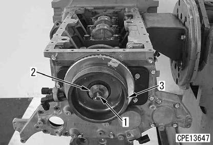
Flywheel assembly
120. Remove the top bolt (1 piece) out of the bolts (1) (6 pieces), and install the guide bolt (H).
121. Remove the remaining bolts (1) (5 pieces).
122. Sling the flywheel assembly (2), and remove it.
4 Flywheel assembly (2):
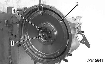
40 kg k Since the faucet joint part of the flywheel is shallow, the guide bolt may fall off suddenly. Be careful not to bring it into contact with you.
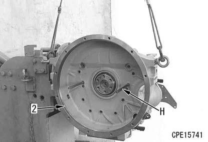
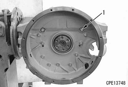
Flywheel housing
123. Remove the top bolts (2 pieces) out of the bolts (1) (11 pieces), and install the guide bolts (H) (2 pieces).
REMARK
Install the guide bolts (2 pieces) to prevent the rear oil seal from being damaged.
124. Remove the remaining bolts (1) (9 pieces).
125. Sling the flywheel housing (2), and remove it horizontally.
4 Flywheel housing (2): 30 kg
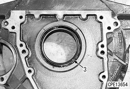
Rear oil seal
126. Screw in the slide hammer (J), etc. to the metallic ring of the rear oil seal (3), and pull out the rear oil seal by using the impact of the slide hammer (J).
NOTICE
Do not use a drill, etc. since metal chips may enter the engine.
REMARK
•Drive in the seal lightly before pulling out the seal to separate it from the housing for easy removal.
•Remove the rear oil seal evenly so that it does not tilt.
Piston and connecting rod assembly
127. By using the dial gauge (L), measure the end play of the piston and connecting rod assembly (1).
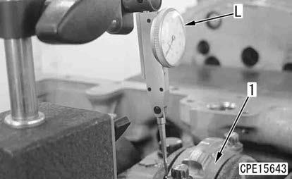
REMARK
Push or pull the piston and connecting rod assembly (1) in the axial direction of the crankshaft to measure the end play.
128. Rotate the crankshaft so that the piston to be pulled out comes to the bottom dead center
129. Rotate the engine repair stand, and set it sideways.
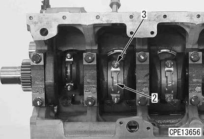
130. Remove the mounting bolts (3) (2 pieces) of the connecting rod cap (2) of the piston and connecting rod assembly (1).
131. Tap the connecting rod cap (2) with a plastic hammer, and remove the connecting rod cap (2) together with the connecting rod bearing as a unit.
REMARK
•Check the stamps on the connecting rod and cap are the same.
•If there are no stamps, stamp on them before disassembling.
132. Push in the piston skirt from the oil pan side by using a wooden rod etc., support the piston on the cylinder head side, push in the piston skirt additionally from the oil pan side, and then pull out the piston and connecting rod assembly (1).
REMARK
When removing, take care not to damage the sliding surfaces of the pistons, connecting rod bearing, etc.
133. Remove the other piston and connecting rod assembly according to the same procedure.
Disassembling the piston and connecting rod assembly
REMARK
• Store them without damaging the sliding surfaces of the pistons, connecting rod bearing, etc.
•Temporarily assemble the connecting rod and cap so that they can be assembled easily. Store them together with the connecting rod bearing.
134. Remove the snap ring (4).
135. Support the connecting rod (5) by hands, pull out the piston pin (6), and disconnect the piston (7) and connecting rod.
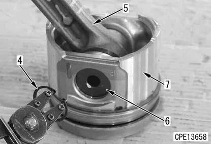
136. Remove the snap ring (4) on the opposite side.
REMARK
If the piston pin (6) cannot be pulled out, soak it in hot water before pulling out.
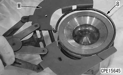
137. By using the piston ring tool (M), remove the piston ring (8) from the piston.
Main cap
138. Measure the end play.
Notice
Measurement of the end play is required for judgment whether the thrust bearing is worn or whether the crankshaft is abnormally worn. Therefore, measure the end play before removing the crankshaft.
1) Set the engine assembly on the engine repair stand so that the oil pan faces upward.

2) Set the dial gauge (L), and measure the end play of the crankshaft.
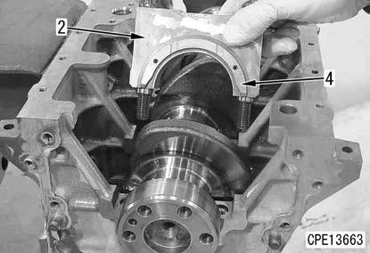
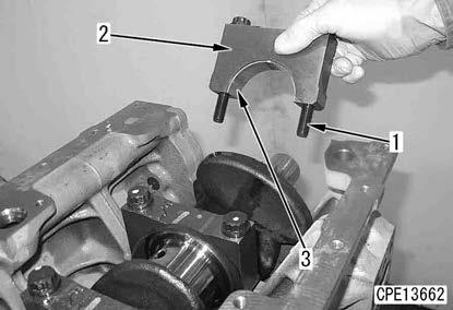
139. Remove the main cap mounting bolts (1) (10 pieces), and remove the main caps (2) (5 pieces).
Remark
Insert the bolt into the bolt hole of the cap, and then remove the cap together with the lower bearing (3) while shaking it or tapping it horizontally with a plastic hammer.
Notice
The thrust bearings (4) are installed to both sides of the main cap (2) on the flywheel side, and check the installing position when removing.
Crankshaft assembly
140. Sling the crankshaft assembly (1), and remove it.
REMARK
Be careful not to damage the sliding part of the crankshaft assembly when removing.
4 Crankshaft assembly (1):
30 kg
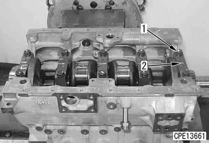
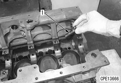
141. Remove the main bearings (2) (5 pieces).
REMARK
•Remove the bearing like pushing down the bearing end.
•Put marks on the installing positions of the main bearing (2) and thrust bearing respectively, and sort them for each main cap number.
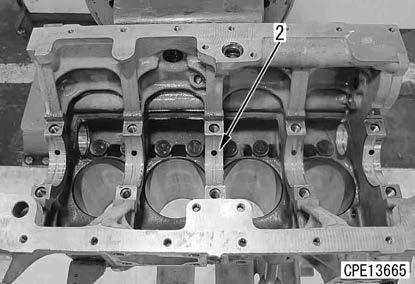
Tappet
142. Remove the tappets (1) (8 pieces) from the cylinder block.
REMARK
• Check that the cam sliding part is not worn.
•If the cam sliding part is worn, the camshaft may be worn. Inspect the camshaft.
Cylinder block assembly
143. Sling the cylinder block assembly (1), hold it, and remove the bolt of the bracket (C).
144. Sling the cylinder block assembly (1) together with the bracket (C) as a unit, and remove them from the engine repair stand (B).
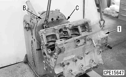
REMARK
Lower the cylinder block assembly (1) on the block, and then remove the bracket (C).
4 Cylinder block assembly (1):
80 kg

DISASSEMBLE AND ASSEMBLE ENGINE GENERALLY
Method For Asembling Engine Generally
Cylinder block assembly Installing to the engine repair stand Tappet Crankshaft assembly
Crankshaft pulley
Oil suction tube Piston, connecting rod assembly A
Flywheel housing Rear oil seal B
Camshaft assembly Front cover C
Engine oil pump assembly Idler gear A Main
B Flywheel assembly
C Front oil seal