4 minute read
DISASSEMBLE AND ASSEMBLE ENGINE GENERALLY


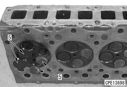
78. Apply engine oil to the valve stem and the valve guide inner surface of the intake and exhaust valve (5).
2 Valve stem and valve guide:
Engine oil
79. Turn the cylinder head (1) upward and install the intake and exhaust valve (5).
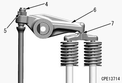
80. Install the valve spring (6) and valve spring seat (7).
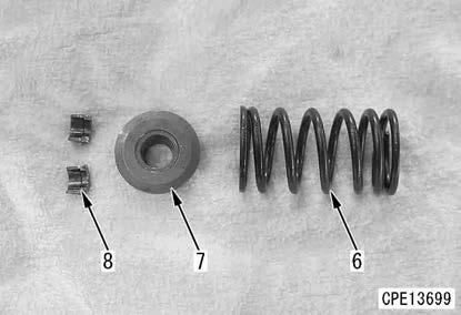
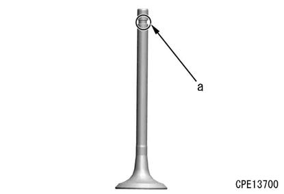
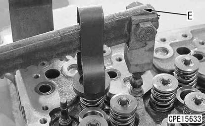
81. By using the spring pusher (E), compress the valve spring (6), and fit in the valve cotter (8) to the groove (a) of the valve stem.
Notice
Check that the cotter (8) is securely fitted into the groove of the valve stem by hitting the valve stem lightly with a plastic hammer.
Cylinder head assembly
82. Invert the cylinder block assembly (10) by using the engine repair stand.
83. Check that the cylinder head and cylinder block mounting surface are free from dirt or foreign material, and then install the cylinder head gasket (9) to the cylinder block assembly (10).
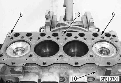
Remark
•Install it so that the mark “TOP” (b) on the cylinder head gasket comes to the upper side.
•Check that pin (13) to prevent the wrong installation of cylinder head gasket on the upper side of the cylinder block and the hole of cylinder head gasket are aligned.
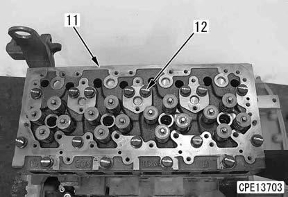
84. Sling the cylinder head assembly (11), and set it to the cylinder block.
4 Cylinder head assembly:
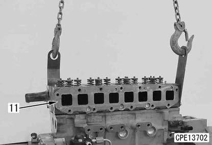
35 kg
85. Apply molybdenum disulfide lubricant to the threaded portion of the cylinder head mounting bolt.
2 Threaded portion of bolt:
Lubricant containing molybdenum disulfide (LMP)
86. Screw in the bolt (12) at least 2 or 3 turns by fingers before tightening it.
87. Tighten the bolt (12) in the order of [1], [2], [3], [4], [5], [6], [7], [8], [9], [10], [11], [12], [13], [14], [15], [16], and [17] as shown in the drawing and in the following order.
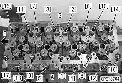
(F): Engine front side
(A): Engine air intake side
(B): Engine exhaust side
3 1st time:
68.6±9.8 Nm {7±1 kgfm}
3 2nd time:
107.8±4.9 Nm {11±0.5 kgfm}
3 3rd time:
90 (+30/0) ° Retighten.
88. Put 1 punch mark (d) on the head of the mounting bolt.
REMARK
•Put 1 punch mark to the head of the bolt every time the bolt is tightened.
•The bolt which has 5 punch marks (d) must be replaced with a new one. Do not reuse it.
•Do not put a punch mark when using a new bolt.
Injector assembly
NOTICE
If the injector assembly was replaced, install the engine to the machine, and then write the injector compensation value to the engine controller. For details, see TESTING AND ADJUSTING, “WRITE INJECTOR COMPENSATION VALUE TO ENGINE CONTROLLER” in the shop manual for the mounted machine model.

89. Check that there is no dust, etc. inside of the fuel injector bore.
NOTICE
•Clean the dirt, etc. around the wiring harness connectors, and remove them completely to prevent them from entering the connectors.
•Use clean engine oil when applying engine oil to O-rings and lubricated parts.
90. Install the gasket (2) to the injector (1).
91. Install O-rings (3) and (4) to the injector (1).
NOTICE
Take care not to wrongly install O-ring to the groove (a).
92. Apply engine oil to O-ring (3) and inserting hole on the head side of the injector (1).
2 O-ring and head side inserting hole: Engine oil
93. Face the fuel inlet hole of the injector (1) to the intake manifold side, and insert it into the cylinder head while inserting the injector holder (5) into the part (b) of the injector.

REMARK
Do not let the gasket at the tip of the injector nozzle fall.
94. Install the injector holder (5) loosely with the bolt (6).
NOTICE
•Replace the bolt (6) with a new one since it is not reusable.
•Do not screw in the bolt (6) excessively.
•When installing the fuel high-pressure pipe, perform positioning of the bolt (6) and tighten it to the specified torque.
Push rod and crosshead
95. Insert the push rod (1) into the tappet guide.
REMARK
•The push rods for the intake and exhaust valves are the same.
•If the push rods are free from defects, install them in the same positions as before.
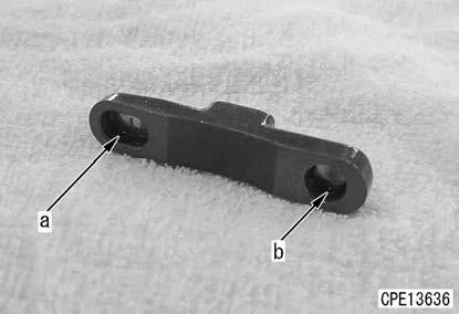
96. Install the crosshead (2).
NOTICE
Install the crosshead so that the long hole (a) faces the exhaust side and the short hole (b) faces the intake side.
Rocker arm assembly
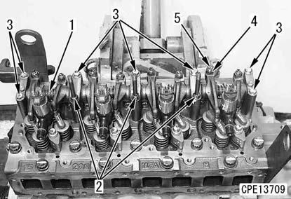
97. Install the rocker arm (1).
98. Check that the ball of the adjustment screw (5) is fitted in the push rod socket securely.
99. Tighten the rocker arm (1) with the stud bolt (2) and bolt (3).

REMARK
Loosen the lock nut (4) and sufficiently return the adjustment screw (5).
3 Bolt (3):
19.6 to 29.4 Nm {2.0 to 3.0 kgfm}
Adjustment of valve clearance
100. Rotate the crankshaft in the normal direction (clockwise viewed from the engine front) to align the notch part (a) of the plate (1) at the rear of the crankshaft pulley with the embossed mark (b) “1.4TOP” of the front cover (2).

REMARK
•Perform cranking while holding the crankshaft pulley bolt (3).
•Be sure to rotate the crankshaft pulley bolt only in the normal rotation direction to prevent it from being loosened.
•Cranking can be performed depending on the machine model.
1) When the plug (c) of the flywheel housing is removed, the mark (painted in white) of the No.1 cylinder top dead center on the flywheel side can be checked.
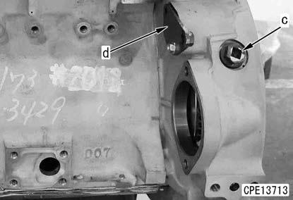
2) When the cover (d) of the flywheel housing is removed, the barring tool for cranking can be installed.
For details, see the shop manual of each model.
3) At the No.1 cylinder compression top dead center, the intake and exhaust rocker arm of the No.1 cylinder can be moved by the valve clearance with hands. If the rocker arm cannot be moved by hands, the No. 1 cylinder is not at its compression top dead center. In this case, rotate the crankshaft one more turn.
101. Adjust the valve clearance marked with ○ in the valve layout drawing according to the following procedure.
1) Loosen the lock nut (5) while the adjustment screw (4) is fixed.
2) Insert the feeler gauge (T) into the clearance between the rocker arm (6) and crosshead (7).
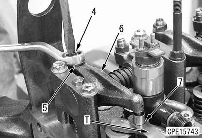
3) Rotate the adjustment screw (4) with the feeler gauge (T) inserted, and then adjust the adjustment screw until the feeler gauge can move lightly.
REMARK
•Adjust the valve clearance within the target value range.
•Valve clearance (when cooled)
Intake side: 0.35±0.02 mm
Exhaust side: 0.50±0.02 mm
4) Tighten the lock nut (5) while the adjustment screw (4) is fixed.
3 Locknut:
39.2 to 49.0 Nm {4.0 to 5.0 kgfm}
5) After tightening the lock nut, check the valve clearance again.
102. Rotate the crankshaft by 1 turn, set the No.4 cylinder to the compression top dead center, and adjust the valve clearance marked with ○ in the valve layout drawing according to the same procedure as the clearance marked with ●.
REMARK
You can rotate the crankshaft pulley by 180 ° each time, and adjust the valve clearance of the cylinders at the compression top dead center of each cylinder (Firing order: 1-2-4-3)