50 DISASSEMBLY AND ASSEMBLY
HOW TO READ THIS MANUAL
RELATED INFORMATION ON DISASSEMBLY AND ASSEMBLY HOW TO READ THIS MANUAL This section describes the special tools, work procedures, and safety precautions necessary for removal, installation, disassembly, and assembly of the components and parts. In addition, tightening torques, quantity, and weight of the coating materials, lubricants, and coolant necessary to these works are shown.
Reading the special tools list •
The special tools required for removal and installation work are described in the list as symbols such as A1, ..., X1. Part number, part name, necessity, and quantity are described.
•
Details of the special tools are on “SPECIAL TOOLS LIST”. Details of sketches are on “SKETCHES OF SPECIAL TOOLS”. Special tools required for a specified work is also described in each work procedures.
•
The symbols used in the table of special tools indicate the following meanings. ■: Not substitutable, and work cannot be performed without the tool. ●: Very useful tools to use which can be substituted with commercially available tools.
Reading the work procedures All the necessary information for the work procedure, the precautions and prior knowledge relating to the work procedures is described step by step.
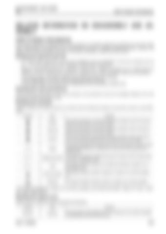
Reading the symbols Important safety and quality portions are marked with the following symbols so that shop manual is used effectively. Symbol
Item
Remark
Danger
This signal indicates an extremely hazardous situation which will result in death or serious injury if it is not avoided.
Warning
This signal indicates a potentially hazardous situation which will result in death or serious injury if it is not avoided.
Caution
This signal indicates a potentially hazardous situation which will result in injury or property damage around the machine if it is not avoided.
Weight
This signal indicates the weight of parts and components, and items which requires great attention to a selection of wires and working posture for slinging work.
Tightening torque
This signal indicates the tightening torque for portions which requires special care in assembling work.
Coat
This signal indicates a place to be coated with adhesive, grease, etc. in assembling work.
Oil and coolant
This signal indicates a place to supply oil, coolant, etc. and the quantity. (*1)
Draining
This signal indicates a place to drain oil, coolant, etc. and the quantity.
*1:For places to supply oil, coolant, etc. and their quantities, see SPECIFICATIONS “TABLE OF FUEL, COOLANT, AND LUBRICANTS”.
Reading the signal word Signal word for notice and remark describes the following. Symbol
Item
Remark
NOTICE
NOTICE
If the precaution of this signal word is not observed, the machine damage or shortening of service life may occur.
95LE-7 SERIES
50-9


