COOLING SYSTEM
10 STRUCTURE AND FUNCTION
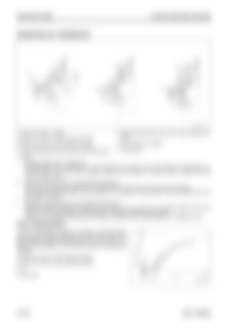
OPERATION OF THERMOSTAT
A: When the valve is closed B: When the valve is crack opened primarily
E: The opening portion of the valve crack opened secondly
C: When the valve is crack opened secondly
F: Flow direction of coolant
D: The opening portion of the valve crack opened pri- L1: Lift amount marily 1. Operation when valve is closed (A) This thermostat has a small-diameter valve mechanism at portion (D) as well unlike the conventional normal thermostat. This small valve is seated (closed) at the shoulder of crimped portion of pellet when the valve is crack opened. 2. Operation when the valve is crack opened primarily (B) The coolant temperature exceeds the set temperature, and the piston starts extension operation. At this time, the small-diameter valve at portion D in the figure is crack opened, and the coolant flows into the radiator through it. 3. Operation when the valve is crack opened secondly (C) When the coolant temperature increases further above lift (L1), portion (D) in the above figure touches the holder and the large-diameter valve at portion E in the above figure is crack opened. At this time, the coolant is flowing into the radiator already, and the water pressure is not affected much.
Flow characteristics The flow characteristics become as shown in the right figure, and the flow fluctuation gradient is low when the lift is low. The flow fluctuation caused by hunting when the valve opens is reduced by this operation, and the thermal shock on the engine is reduced. A: When the valve is crack opened primarily B: When the valve is crack opened secondly. L: Lift Q: Flow rate
10-108
95LE-7 SERIES


