Cat Feeder Breaker FBL-10 LHD/Utility Service Manual – PDF DOWNLOAD

Page 361

BI620114

Service Manual

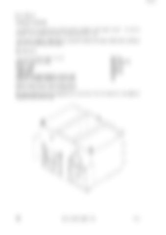
CONCRETE HOPPER The hopper is designed to be carried by the machine’s RAS attach system. The primary purpose is to transport concrete to various parts of the mine. The concrete hopper is fitted with one access/fill section at the top and two delivery Shute's fitted with manually operated gates. Specifications Tare mass of hopper (approximate): Maximum load (concrete): Hopper length: Hopper width: Total height: Maximum vehicular inclination (front to rear): Maximum vehicular inclination (side to side):

4300 kg 9651 kg (4 M³) 2094 mm 2430 mm 1700 mm 1:4 1:8

Platform Raise/Lower and Tilt Adjustment All raising, lowering and tilt adjustment are carried out from the operator’s compartment using the lift and tilt controls.

352

FBL-10 LHD/Utility Serial No. 1600

Rev. 2


Turn static files into dynamic content formats.

Create a flipbook

Articles inside

Concrete Hopper

1min
pages 361-362

5th Wheel Adaptor Materials Pod………………………………………………341

3min
pages 348-351

Elevated Work Platform

2min
pages 358-360

10000 KG Fixed Jib Crane

1min
pages 346-347

15000 KG Side Shit Forks

1min
pages 344-345

Spade Lip Ejector Blanket Straight Lip Ejector Blanket………………………………333 RAS Ejector Blanket………………………………………334

3min
pages 341-343

Safety Precautions

1min
page 340

General Description

1min
pages 338-339

Operator’s Horn

1min
page 335

Starter Motor

1min
page 331

Safe Start System

1min
page 333

Brake and Transmission Interlock System

1min
page 334

Air Receiver

4min
pages 328-330

Articulation Joint

1min
page 320

Compartment Door Assembly

1min
page 316

Fault Guide

5min
pages 305-306

DCS Concept

5min
pages 279-281

Testing Methane Sensor

1min
page 304

System Operation

1min
page 278

System Hardware

1min
page 282

Sensors and Locations

3min
pages 284-287

Bypass Switch

1min
page 277

Checks and Calibration

1min
page 276

Compartment Door

1min
page 252

Methane Sensor Head

1min
page 275

Control Lever Maintenance

1min
page 256

Emergency Intake Shut Off Valve

1min
page 266

Steering Wheel

1min
page 258

Alternator Drive Assembly Instruments and Controls

1min
pages 250-251

Engine Service Hour Meter

2min
pages 245-246

Electric Lighting Components

2min
pages 242-244

Alternator Circuit and Cooling Fan

1min
pages 236-237

Main Control Valve Bank

1min
pages 232-233

RAS Attach and PTO Circuits

1min
page 235

Control Levers

1min
pages 230-231

Tilt and Lift Circuits

1min
page 234

Brake Heads Attachment Controls

1min
page 229

Brake Valve

5min
pages 225-228

Steering Control Valve

1min
page 223

Steering/Brake Pump Pressure Filter

2min
pages 220-221

Hydraulic Tank Checking and Filling Hydraulic Oil

1min
page 212

Checking and Cleaning Filler Neck Screen

1min
page 214

Steering and Brake Hydraulic Manifold

3min
pages 216-219

Checking and Replacing Return Filter

1min
page 215

Auxiliary Hydraulic Pumps

1min
page 211

Pumps and Mountings Steering/Brake Pump

2min
pages 207-209

Safety Precautions

1min
page 205

General Description

2min
page 204

Installation

1min
page 203

Safety Precautions

1min
page 197

Removing and Installing the Upper Drive Line

1min
page 200

General Description

1min
page 196

Removing and Installing the Front Drive Line

2min
page 199

Checking Wear of the Posi-Stop Brake Assemblies Drive Lines

1min
page 195

Cooled Brakes

2min
pages 193-194

Checking/Filling the Axle Centre Oil Level Changing the Oil In Axle Centres, Wheel Ends, and Liquid

1min
page 192

Checking/Filling the Planetary Wheel End Oil Level

1min
page 191

Changing the Transmission Oil

1min
page 184

Service Data

2min
pages 187-189

Changing the Transmission Oil Filter Element

1min
page 183

Troubleshooting Guide

2min
pages 185-186

Checking/Filling the Transmission Oil

1min
page 182

Safety Precautions

1min
page 181

Transmission and Torque Converter General Description

4min
pages 179-180

Removal and Installation of Drive Coupling

1min
page 178

Flushing a Contaminated Cooling System Exhaust System

1min
page 156

Exhaust Particulate Filter

1min
pages 166-167

Checking/Filling and Flushing Coolant System

2min
page 155

General Description

1min
page 157

Radiator

1min
pages 153-154

Fan Assembly

1min
page 151

Servicing Air Intake System Cooling System

1min
pages 146-147

Inlet Flame Trap/Flameproof Joints

1min
page 145

Flushing the Lubrication System Air Intake System

1min
page 141

Emergency Intake Shutoff Valve

1min
page 144

Oil Filter

1min
page 139

Safety Precautions

1min
page 138

Air Cleaner/Indicator Assembly

2min
page 143

General Description

1min
page 137

Fuel System – Priming Lubrication System

1min
page 136

Safety Precautions

1min
page 131

500 Hours—6 Months Off Line Mechanical Inspection

10min
pages 68-79

250 Hours—3 Months Off Line Mechanical Inspection

10min
pages 56-67

1000 Hours—12 Months Off Line Mechanical Inspection

10min
pages 80-91

5000 Hours—5 Yearly Off Line Mechanical Inspection

10min
pages 104-115

50 Hours—Weekly Off Line Mechanical Inspection

9min
pages 46-55

Diesel Fuel Relevant Information

2min
page 19

10 Hours—Daily Off Line Mechanical Inspection

8min
pages 36-45

Specifications Lubrication and Fuel Specifications

3min
pages 15-16

Fuel Additives

1min
page 18

Articulation Isolation

1min
page 28

Packing and Supporting the Machine

1min
page 33

Maintenance Schedules

1min
pages 34-35

General Safety and Precaution General

3min
pages 30-32
Issuu converts static files into: digital portfolios, online yearbooks, online catalogs, digital photo albums and more. Sign up and create your flipbook.
Cat Feeder Breaker FBL-10 LHD/Utility Service Manual – PDF DOWNLOAD by www.heydownloads.com - Issuu