4 minute read
Air Receiver


AIR RECEIVER
The air receiver accepts air pumped from the air compressor and stores it at a maximum pressure of 830 kPa (120 psi) as set by the governor valve mounted on the side of the compressor. A pressure relief valve mounted on the air receiver ensures that the maximum stored pressure does not exceed 860 kPa (125 psi). The base of the air receiver is fitted with a drain cock to enable stored pressure to be safely directed away from personnel, as well as provide low drain point for the removal of water. Air is delivered to the air receiver via a one-way check valve to retain air pressure when the engine has stopped.
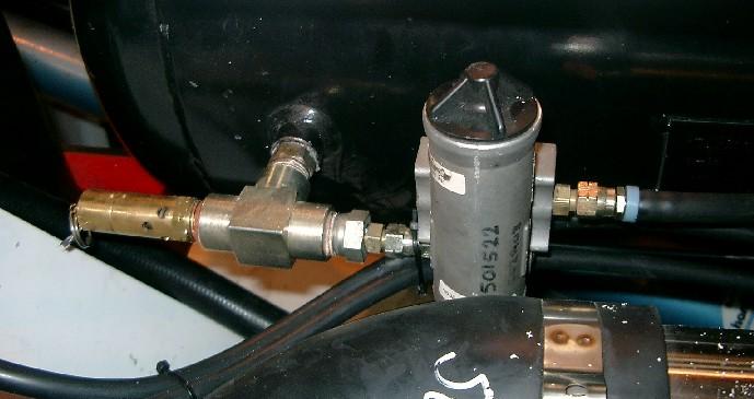
A three-way ball valve is also fitted to enable air receiver filling from an external air supply. The valve has three positions in, off, tank.
To fill the air receiver via an external air hose:
1. Connect an external air supply to the min-sup coupling and fit safety pin. 2. Rotate the three-way ball valve from the tank to the off position and apply air pressure from the supply hose. 3. Rotate the ball valve from the off to the in position. This allows air to be delivered into the air receiver. 4. Once the correct air pressure has been obtained (observed at the air pressure gauge in the operator’s compartment) turn the external air pressure off. 5. Rotate the three-way ball valve to the tank position. This opens the supply hose to the drain line and closes the inlet to the tank. Pressure in the hose is relived via the drain line to enable easy and safe disconnection of the min-sup coupling.
Main Air Fill Valve
Main Air Manifold
Main Air Drain Valve
Main Air Isolation Valve
Servicing
The air receiver should be drained of accumulated water daily.
To drain the air receiver:
1. Ensure that the engine has had sufficient time to cool and is isolated and tagged as described in Section 1. 2. Locate the main air drain valve at the lower most point on the air receiver. 3. Open the main air drain valve allowing water to be purged from the tank. It is not necessary to drain all air from the air receiver. A short burst of released air is sufficient.
The governor valve should be checked for correct operation every 250 service hours.
To check for correct operation:
1. Start the engine and ensure the external air supply is isolated. 2. Observe the air pressure gauge in the operator’s compartment. The compressor should unload at 120 psi. 3. To check that the governor valve is loading, bleed air from the air receiver at approximately 80 psi.
NOTE: The pressure differential between loaded and unloaded is fixed at 30 psi 40 psi and it can not be adjusted.
To check for the correct governing pressure simply observe the maximum and minimum pneumatic pressure on the pressure gauge located in the operator’s compartment. Pressure in the system should constantly rise to a maximum of 830 kPa (120 psi) with a tolerance of -5 psi. If the governed pressure is outside this range, adjustment is required.
To adjust the governor valve for the correct pressure:
1. Start the engine. 2. Locate the governor valve and remove the dust cap on the bottom of the canister. 3. Loosen the lock nut and rotate the adjusting screw clockwise to increase the governed pressure or counter-clockwise to reduce the governed pressure. 4. Verify governed pressure by running the engine and viewing the maximum pressure indicated on the pneumatic air pressure gauge located in the operator’s compartment. 5. When 120 psi is reached lock the lock nut and replace the dust cap.
The air receiver pressure relief valve should be checked for correct relief setting every 3000 service hours.
Dust Cap (Remove to locate adjusting screw)
Governor Valve
To check and adjust the air receiver relief valve:
1. Start the engine. 2. Observe the pressure on the air pressure gauge in the operator’s compartment. 3. Locate the governor valve located on the side of the compressor. 4. Rotate the governor adjusting screw clockwise to increase the pressure to 125 psi on the gauge in the operator’s compartment. 5. Locate the relief valve on the air receiver and adjust until the air lifts the seat and starts venting to atmosphere. 6. Lock the relief valve at this setting. 7. Rotate the adjusting screw counter-clockwise on the governor screw on the side of the compressor to reduce the governed pressure. 8. Drain air from the air receiver till the operator’s air pressure gauge is 70 psi. 9. Let the air pressure build up until governed pressure is reached. 10. Rotate the adjusting screw clockwise to increase the pressure. 11. When 120 psi is reached on the gauge in the operator’s compartment lock the lock nut on the adjusting screw and replace the dust cap. 12. Drain some air from the air receiver and let the pressure build up to check if the governed pressure maintains 120 psi on the gauge in the operator’s compartment.
The air receiver is a pressure vessel inspection and certification of the air receiver must be carried out every 12 months by a licensed boiler inspector.