1 minute read
General Description


LUBRICATION SYSTEM
GENERAL DESCRIPTION
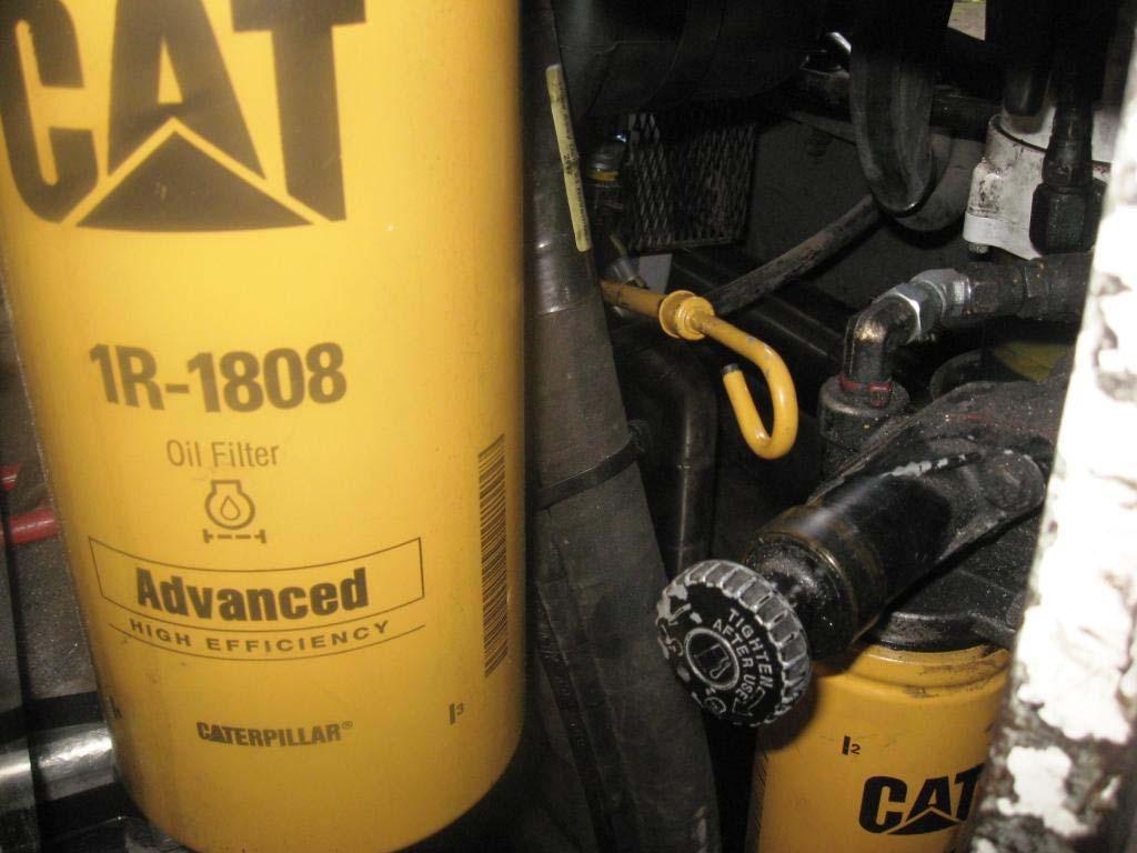
The engine lubrication system provides essential lubrication for the engine working components. The system consists of an engine oil reservoir (sump), and level gallery, oil pump, oil pressure regulator and relief valve, oil cooler, and filter assembly. Lubricating oil is drawn by suction from the oil pan (sump) via the intake screen to the pump where it is pressurised. Oil then passes through a short gallery in the engine cylinder block to the oil cooler housing. At the same time oil is directed to the relief valve where excess oil is discharged back to the sump when the pump pressure exceeds 600 kPa (88 psi). From the oil cooler adaptor plate oil passes through the full flow filter, through the oil cooler then back into the cylinder block where the oil is internally routed. Bypass valves are located at the oil cooler and filter assemblies to maintain flow if either become blocked.
Stabilised oil pressure is maintained within the cylinder block by a pressure regulator valve located in the cylinder block oil gallery opposite to the cooler. The regulator discharges oil back to the sump if the pressure at the valve exceeds 345 kPa (50 psi). Regulated oil is forced through the various working components within the engine.
A low oil pressure sensor is located behind the operator’s display panel. This sensor activates at an oil pressure below 70 kPa (10 psi) and shuts down the engine via the electronic shutdown system.