3 minute read
Steering and Brake Hydraulic Manifold


STEERING AND BRAKE HYDRAULIC MANIFOLD
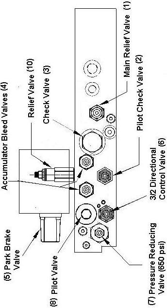
The main hydraulic manifold interfaces the steering/brake pump to the steering and brake circuits and provides steering interlocking as well as accumulator automatic drain on loss of brake release pressure. The manifold also provides reduced pressure to the controls for the lift arm and attachment functions. Machine hosing is simplified with the manifold, providing only one tank return line and one pressure line connection.
The steering/brake system pressure is primarily governed by the compensated pressure setting of the steering/brake pump. The system normally is set to a compensated pressure of 17.2 MPa (2500 psi). The system is backed up by a system relief valve mounted in the main hydraulic manifold set to divert flow to tank at a relief pressure of 20.7 MPa (3000 psi). The relief valve would not factor into normal system operation however, should a system failure occur the relief valve will limit available pressure to 20.7 MPa (3000 psi).
The steering/brake system relief valve setting should be checked at 2000 service hours.
To check and adjust the relief valve setting:
1. Park the machine in a clear area, apply the park brake and install the articulation lock and chock the wheels. 2. With the engine running at idle access the steering/brake pump by removing the transmission cover and locate the pressure compensator adjustment on the side of the pump housing. 3. Release the park brake. 4. Loosen the adjusting screw lock nut and rotate the adjusting screw clockwise to increase the compensating pressure. 5. Have an observer watch the steering or brake accumulator pressure gauge while increasing the pump compensating pressure. 6. When the pressure approaches 20.7 MPa (3000 psiI) the relief valve will operate forcing the pump to remain on stroke. If this is the case then the relief valve is correctly set. 7. If the pump fails to come on stroke or comes on stroke too early it will be necessary to adjust the relief valve pressure setting. 8. Locate the relief valve on the main hydraulic manifold. 9. Loosen the lock nut and rotate the relief valve adjusting screw clockwise to increase the relief pressure and counter-clockwise to decrease the relief pressure. 10. When the correct main relief valve adjustment is achieved tighten the adjusting screw lock nut. 11. Adjust the compensator valve back and reduce the pressure in the system to below 2500 psi by working the steering or brakes. 12. Adjust the compensator on the steering/brake pump screw to bring the pressure back to 2500 psi when this is correct lock the compensator adjustment screw. 13. Refit the covers.
The main hydraulic control valve is supplied at reduced system pressure via a pressure reducing valve located in the main hydraulic manifold.
The pressure reducing valve setting should be checked every 2000 service hours.
To check and adjust the pressure reducing valve setting:
1. Ensure the machine is isolated and tagged as described in Section 1. 2. Ensure that both accumulators are completely drained of oil pressure as per Section 1. 3. Locate the main hydraulic manifold. 4. Locate either port P2 or P3 on the main manifold block. These ports are supply ports from the manifold to the No. 1 and No. 2 two-way hydraulic control levers at reduced pressure. 5. Remove either hose from P2 or P3 and install a pressure gauge with a full scale deflection of 6.89 MPa (1000 psi). 6. With the engine running at idle observe the pressure at the gauge. This pressure should read 4.5 MPa (650 psi). 7. If the pressure requires adjustment locate the pressure reducing valve on the main manifold. 8. Loosen the lock nut and rotate the reducing valve adjusting screw clockwise to increase the pressure and counter-clockwise to decrease the pressure. 9. When the pressure reaches 4.5 MPa (650 psi) the reducing valve is correctly set. 10. Tighten the adjusting screw lock nut, shutdown the machine, isolate hydraulic pressure, remove the gauge and reconnect the hose.
Ensure that all accumulator pressure is removed before disconnecting hydraulic hoses.
The drive line inside the compartment which contains the main manifold is rotating whenever the engine is running. Keep clear of the rotating parts when accessing this compartment with the engine running.


Main Hydraulic Manifold