5 minute read
Brake Valve


BRAKE VALVE
The brake pedal operates a brake valve which delivers oil to the brake units at a pressure, set by its own regulator, and proportionally dumps this pressure relative to the stroke of its actuating push rod when the operator applies the brakes.
The brake valve is mechanically linked to the brake pedal. Application of the brake pedal will stroke the valve push rod, removing pressure from the spring applied, hydraulic released brake units back to tank. The amount of pressure removed from the brake units, hence the severity of brake application, will be proportional to the stroke of the push rod.
When the brake pedal is released maximum regulated pressure (1650 psi-1750 psi) is delivered to the brake units, releasing the brakes.
Pressure regulation and reverse modulation is achieved via internal shimming inside the valve block head. No serviceable components exist in the brake valve. If the brake head pressure, indicated by the pressure gauge in the operator’s compartment is outside the normal operating range the valve should be replaced.
A high pressure delivered to the brake heads can damage the piston seals.
A pressure below 1600 psi will cause the brake plates to drag cause heat build up and excessive wear. The brake valve should be resealed and bench tested every 5000 hours.
Brake head pressure should be checked daily.
To verify brake head pressure:
1. With the machine running release the park brake. 2. Remove your foot from the brake pedal and record the brake head pressure on the gauge in the operator’s compartment. 3. Brake head pressure should be 1700 psi. 4. Remove and replace the brake valve if release pressure is outside this range.
Brake Valve
Disassembly:
1. Depress pedal and remove pedal stop screw and jam nut from base. Also loosen jam nut for later removal of clevis. 2. Remove cap screws and lock washers from base. 3. Remove e-rings from ends of pins. Remove pins.
NOTE: Some models use threaded studs, in place of pins and e-rings. 4. Remove set screw from pedal. Remove e-rings from both ends of pin.
NOTE: Not all models use e-rings. 5. Separate pedal and base by removing pin through clearance hole in pedal. Remove pedal and base. 6. Temporarily insert pin into clevis and record distance from top of pin to mounting flange of housing. This measurement will be necessary for reassembly purposes.
NOTE: Apply slight downward force on clevis while taking measurement to assure that rod is in contact with piston. 7. Remove clevis and jam nut from rod. 8. Separate housings by removing cap screws and lock washers. 9. Remove rod, piston, spring, spring and washer from housing. Remove boot (2) from housing.
NOTE: Not all models use spring or washer. 10. Remove piston, shim(s) (6) and spring (7) from housing bore. Note number of shims being removed for reassembly purposes. 11. Remove o-ring (2) from housing bore.
NOTE: Be careful not to scratch or mark the housing bore. 12. Remove retaining ring from housing bore
NOTE: Be careful not to scratch or mark the housing bore. 13. Remove retainer from housing bore. 14. Remove retaining ring (2) from housing bore. 15. Remove piston and sleeve assembly (5) from housing bore. Separate piston (5) from sleeve. 16. Remove o-ring (2) and backup ring (2) from sleeve. 17. Remove spring from housing bore. 18. Remove cup (2) and backup ring (2) from piston (5).
NOTE: A check ball is located inside piston (5). Make sure ball is clean and moves freely. Some models use an o-ring in place of cup (2) and backup ring (2). 19. Remove plug from housing. 20. Remove o-ring (2), cup (2), backup ring (2), washer, spring and guide (4) from plug.
NOTE: Some models use an o-ring in place of cup (2). 21. Remove cage (2) from housing bore. 22. Remove valve assembly (3) from housing bore. 23. Remove o-ring (2) from valve assembly (3). 24. Remove plug and ball (2) from housing. Remove o-ring (2) from plug.
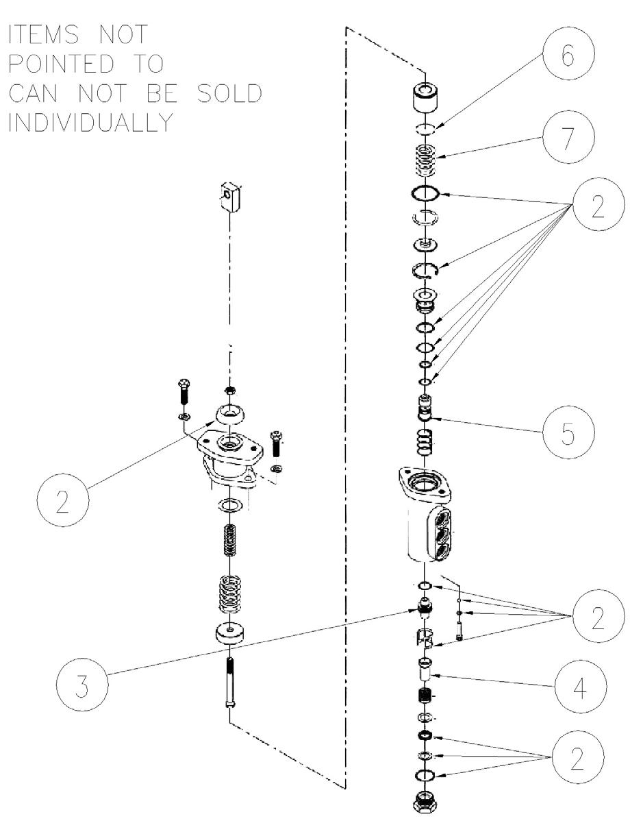
Key
(1) Kit - Complete Rebuild - Brake Valve (2) Kit - Seal - Brake Valve (3) Valve - Ball Assembly - Brake Valve (4) Guide Assembly - Brake Valve (5) Piston Assembly - Brake Valve (6) Shim Kit (7) Brake Valve Spring
Assembly:
Clean and inspect all parts for wear. Lubricate all rubber components from repair kit with clean system fluid.
1. Install new o-ring (2) on plug. Install new ball (2) and plug in housing. Torque plug 88.1-101.7 N-m (65-75 Ib-in). 2. Install new o-ring (2) on valve assembly (3) and insert into housing bore. Note the direction of valve assembly.
NOTE: Be sure valve assembly seat is fully seated into housing. 3. Install new cage (2) into housing bore. 4. Install new o-ring (2) on plug. 5. Insert new backup ring (2) and new cup (2) inside end of plug. Note order of back up ring and cup.
NOTE: Some models use an o-ring in place of cup (2). 6. Install guide (4), spring and washer in end plug. Install plug in housing and torque 54.3-67.8 N-m (40-50 Ib-ft). 7. Install new cup (2) and new backup ring (2) on piston (5) and insert into sleeve. Note direction of piston and sleeve.
NOTE: Some models use an o-ring in place of cup (2) and backup ring (2). 8. Install new backup ring (2) and new o-ring (2) on sleeve. 9. Install spring on piston (5). 10. Install piston and sleeve assembly (5) in housing bore. Note direction of assembly. 11. Install new retaining ring (2) in housing bore. 12. Install retainer and retaining ring in housing bore.
NOTE: Be careful not to scratch or mark housing bore 13. Install new o-ring (2) in housing bore. 14. Install spring (7), shim(s) (6) and piston in housing bore. Be sure to install the same number of shim(s) as were removed during disassembly. 15. Lightly coat inside bore of housing with graphite based grease and install new boot (2) on housing. 16. Apply graphite based grease sparingly to piston in chamfered area where rod makes contact. 17. Insert rod, piston, spring, spring and washer into housing (34). NOTE: Not all models use spring or washer. 18. Attach housings using cap screws and lock washers. Torque 29.8-36.6 N-m (22-27 Ib-ft). 19. Install jam nut and clevis on end of rod. Adjust the clevis to the distance recorded during disassembly. Lubricate all bushings and pins with graphite based grease before assembling the pedal and base. 20. Fully depress pedal and torque jam nut 27.1-32.5 N-m (20-24 Ib-ft) against clevis. 21. Install pedal stop screw and jam nut.
NOTE: With pedal in the release position, adjust pedal stop screw and jam nut so there is .38 mm-.76 mm (.015"-.030") of clearance between the pedal and top of pedal stop screw. Torque jam nut 27.1-32.5 N-m (20-24 Ib-ft).