Cat Feeder Breaker FB110 Operation and Maintenance Manual – PDF DOWNLOAD

Page 59

BI001519

_______________________________________________________ Operation WARNING! The pressure regulator should never be adjusted above 125 psi. dust suppression system regulator

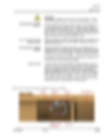
The dust suppression system regulator (Fig. 21) is located below the breaker power unit on the right side of the machine and is used to control the water pressure to the six spray nozzles located in the hose crossover tray over the breaker shaft. The water pressure to the nozzles is monitored by the dust suppression system pressure gauge (Fig. 21). To increase pressure, turn the regulator handle in (cw). To decrease pressure, turn the regulator handle out (ccw).

dust suppression system pressure gauge

The dust suppression system pressure gauge (Fig. 21) is used to monitor the water pressure to the spray nozzles. The gauge should read between 5 and 125 psi.

dust suppression system strainer

The dust suppression system strainer (Fig. 21) is located below the breaker power unit on the right side of the machine and is used to filter particles from the mine water supply. The strainer should periodically be flushed to avoid becoming clogged. To flush the strainer, turn the ball valve handle, located on the branch of the strainer body, 90° in-line with the outlet. Allow to flush for approximately thirty seconds to one minute and then close the ball valve handle.

water solenoid

The water solenoid is located beside the regulator/strainer assembly and is used to control flow of water to the six spray nozzles located in the hosed crossover tray over the breaker shaft. The solenoid is controlled by a pressure transducer located in the hydraulic pressure gauge manifold beside the primary valve bank. When the “MAN/OFF/ AUTO” switch on the starter enclosure is set to “AUTO”, the “TRAM/ OFF/CONV” switch is set to “CONV”, and the hydraulic system pressure reaches 1,200 psi, the solenoid will open and allow water to flow through the water/oil cooler and then to the spray bars.

Fig. 21: Dust suppression system regulator and pressure gauge Gauge

Regulator

Machine wash down port

Strainer

Water solenoid

Ball valve

______________________________________________________________ A6474X435 REV 2 5.15


Turn static files into dynamic content formats.

Create a flipbook

Articles inside

Breaker power unit ....................................................... 5

8min
pages 174-181

Conveyor drive motor ................................................... 5

3min
pages 186-189

TAC monitor for conveyor speed sensor ............. 5

1min
pages 160-161

Crawler track ............................................................... 5

3min
pages 162-164

Lift cylinder ................................................................... 5

2min
pages 193-195

Chain elongation measurement ........................... 5

4min
pages 156-159

Breaker bit removal ...................................................... 5

1min
page 190

Crawler assembly ........................................................ 5

8min
pages 165-173

Main relief pressure ....................................................... 5

1min
page 139

Main pump adjustments ................................................ 5

1min
pages 137-138

Head shaft sprockets ................................................... 5

4min
pages 146-148

Procedure to set Amplifier Card ......................................... 5

2min
pages 128-129

Pressure limiter adjustment ........................................... 5

1min
pages 140-141

Crawler track adjustment .............................................. 5

2min
pages 132-133

Inspection of the fire suppression system .......................... 5

1min
pages 124-125

Breaker drive chain adjustment ..................................... 5

2min
pages 134-135

Every 3 months ............................................................. 5

1min
page 116

Breaker and breaker power unit assembly .................... 5

1min
page 94

Conveyor drive ............................................................. 5

1min
page 92

Monthly ......................................................................... 5

1min
pages 113-115

Major hydraulic components .......................................... 5

3min
pages 82-83

Primary hydraulic circuit ................................................ 5

1min
pages 84-86

Head shaft .................................................................... 5

1min
page 91

Starter enclosure ........................................................... 5

3min
pages 76-79

Electrical system ................................................................. 5

1min
page 73

Shutdown procedure .......................................................... 5

1min
page 67

“AUTO” mode starting procedure ....................................... 5

1min
page 65

Tramming the machine ....................................................... 5

1min
page 68

Conveyor operation ............................................................ 5

3min
pages 69-70

“MANUAL” mode starting procedure .................................. 5

1min
page 66

Dust suppression system .............................................. 5

2min
pages 59-60

Radio remote ................................................................. 5

3min
pages 61-64

Control system operating parameters ................................ 5

2min
pages 71-72
Issuu converts static files into: digital portfolios, online yearbooks, online catalogs, digital photo albums and more. Sign up and create your flipbook.