3 minute read
Starter enclosure ........................................................... 5


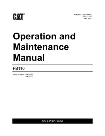
Fig. 25: Starter enclosure Starter enclosure
The starter enclosure, located on the left side of the machine, houses the primary electrical control components.
WARNING! Before removing the cover from the starter enclosure and attempting any maintenance or troubleshooting on the machine, the main power must be disconnected and locked and tagged out at the main power center.
There are operational controls located on the front of the starter enclosure (Fig. 25). For control descriptions, see the Controls and Indicators section in this chapter.
1 2 3 4
5 6
7 8
9 10
11 12 13
1. “MAN/OFF/AUTO” selector switch 2. “TRAM/OFF/CONV” selector switch 3. “FWD/OFF/REV” selector switch 4. PLC display 5. “CB RESET” pushbutton 6. “CONVEYOR START” pushbutton 7. “CONV. HOUR METER” digital display 8. “START BREAKER” pushbutton 9. “STOP” pushbutton 10. “ACKNOWLEDGE ALARMS” pushbutton 11. “BRKR. HOUR METER” digital display 12. “EMERGENCY STOP” pushbutton 13. Main circuit breaker reset lever
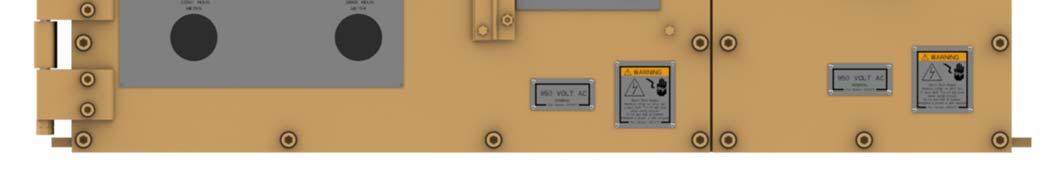
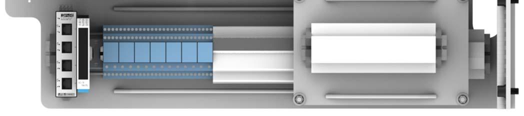
Fig. 26: Swing panel, front side Swing panel - front side
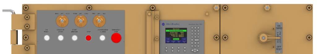
The swing panel (Fig. 26) is accessed by opening the cover on the enclosure. Immediately adjacent to the swing panel is the main circuit breaker, CB1, for the feeder breaker.
Note that component locations are typical. Always consult the parts book for your machine to verify locations.
1 2 3 4 5 6 7 8
9 10 11 12 13 14
1. TAC Monitor 2. Power Supply 3. CompactLogix w/ Ethernet & 64 MB Flash Memory
Card 4. CompactLogix power supply 5. 8 Channel Analog Input Module 6. 2 Channel Analog Outpout Module 7. 120 VAC Input Module 8. 8 Point Output Module 9. 5 Port Ethernet Switch 10. 24 VDC Dual Channel Switching Repeater 11. 3 amp Relays (7) 12. 12 amp Time Delay Fuse (5) 13. 2 amp Time Delay Fuse (2) 14. Multi-circuit Terminal Block (on and behind offset panel)
TAC monitor
power supply
CompactLogix w/ Ethernet & 64 MB flash memory card
CompactLogix power supply
8 channel analog input module
2 channel analog output module
120 VAC input modules
8 point output module
5 port Ethernet switch
24 VDC dual channel switching repeater
3 amp relays
12 amp time delay fuses
2 amp time delay fuses
Multi-circuit terminal block
The TAC monitor picks up the conveyor shaft and pick break speeds and sends a signal to the PLC.
The two power supplies convert 120 VAC to 24 VDC to power solenoids, pressure transducers, etc.
The Compact Logix unit contains the PLC program and is the “brain” of the control system.
The Compact Logix power supply provides power for the Compact Logix unit.
The analog input module receives inputs from the current transducer, pressure transducer, vacuum transducer, and TAC monitor.
The analog output module sends a signal to the amplifier boards.
The 120 VAC input module receives 120V inputs (selector switches, push buttons, etc.).
The 8 point output module sends signals to the 120V input devices.
The 5 port Ethernet switch provides programming access.
The 24VDC dual channel switching repeater is an intrinsically safe relay for the tape switches.
The 3 amp relays are as follows: starting from left, CHM, R1A, CR2, CRR, SSR, WS, and CR1
The 12 amp time delay fuses protect the circuits.
The 2 amp time delay fuses protect the circuits.
The multi-circuit terminal block allows connection between multiple device.
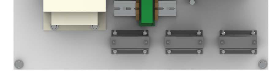
Back panel
The back panel (Fig. 27) is accessed by removing the swing panel retaining bolt located in the upper left hand corner of the swing panel and swinging the panel out. Note that component locations are typical. Always consult the parts book for your machine to verify locations.
Fig. 27: Back panel, typical
1 2 3

4 5
1. Control Transformer 2. Overload Relay 3. Vacuum Contactor 4. Current Transducer 5. Current Transformers
Control Transformer
Overload Relay
Vacuum Contactor
Current Transducer
Current Transformers
The control transformer reduces the voltage to the control circuit from 950V to 120V.
The overload relay is for the pick break motor. If the pick break motor is overloaded, the relay will shutdown the motor.
Vacuum contactor is for the pick break motor.
The current transducer converts the current to a 4-20 mA signal that is relayed to the analog input module and is then displayed as full motor current on the PLC display.
150:5 current transformers used to step down the current.