8 minute read
Breaker power unit ....................................................... 5


Power unit
The power unit (Fig. 80) has been assembled as a unit and can be removed as a unit or as individual components. As soon as any component of the power unit is worn or damaged, the component must be replaced.
The power unit consists of the following main components:
■ gear pump
■ pump coupling
■ motor (200 hp)
■ reducer/motor coupling
■ reducer
■ sprocket
■ connecting tube
■ bearing
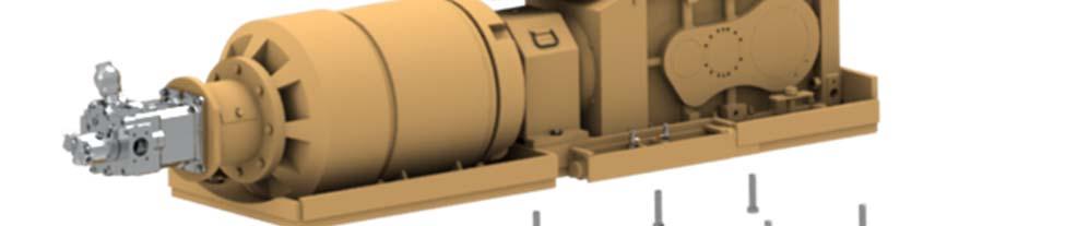
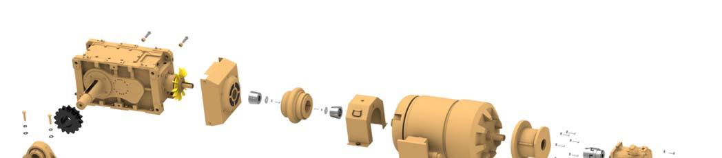
Fig. 80: Power unit main components
Sprocket Reducer Reducer/motor coupling Connecting tube
Motor (200 hp)
Pump coupling
Bearing Gear pump
How to remove the power unit assembly
Whenever performing maintenance procedures, follow all safety regulations and be aware of the following:
WARNING! Before performing maintenance on the machine, the circuit breaker must be in the “OFF” position and the power should be disconnected at the main power source. Electrical shock and accidental machine movement can cause serious injuries or even death to you or the maintenance person.
To remove the breaker power unit proceed as follows (Fig. 81).
1. Turn the machine main circuit breaker (CB1) to the “OFF” position.
2. Lock out and tag the power center. Follow standard Federal and mine lockout/tagout procedures.
3. Remove all power unit covers.
4. Attach an appropriate lifting device to the power unit assembly in such a manner as to keep the power unit level during the lift. Take all slack out of the lifting device in order to support the assembly .
5. Remove the junction box access panel of the electric motor. Tag and disconnect the cable leads from the motor leads.
6. Reinstall the junction box cover.
7. Remove and cap all grease lines from the gear reducer and electric motor.
8. Separate and remove breaker drive chain (see Breaker drive chain adjustment and removal in this chapter)
9. Pull the cotter pins to remove the hex bolt guards covering the nine (9) mounting base bolts. Remove bolts.
10. Lift the power unit out of the machine.
WARNING! You could be seriously injured or even killed by falling loads. Observe the safe working load limits of lifting or blocking devices and keep a safe distance from suspended loads.
How to install the power unit
Note: Before installing the power unit, ensure all dirt and debris is cleaned from the area so that the unit will sit flat in the machine.
To install the power unit as a complete assembly proceed as follows (Fig. 81):
1. Attach an appropriate lifting device to the complete unit and slowly lift the unit onto the machine and align mounting base holes with holes in the frame.
2. Secure mounting base to frame with the nine (9) base bolts, flatwashers, and nuts previously removed. Do not tighten.
3. Connect all hydraulic hoses to the hydraulic pump.
4. Remove the junction box cover.
5. Connect all electrical wiring to the drive motor. Replace junction box cover.
6. Connect all grease lines to the drive motor and gearbox.
7. Connect the drive chain. (See Breaker drive chain installation and adjustment in this chapter). Install mounting bolt guards with cotter pins.
8. Apply an adequate amount of hydraulic oil on the drive chain, if necessary.
9. Check oil level in gearbox. Oil should be visible in the lower sight glass only.
10. Install power unit covers.
Fig. 81: Power unit removal and installation
Power unit

Hex bolt guards and cotter pins
Mounting bolts

How to disassemble the power unit (Fig. 82)
Whenever performing maintenance procedures, follow all safety regulations and be aware of the following:
WARNING! Before removing each pump and the connecting tube be sure to properly support the component. Failure to properly support the component may result in damage to the component or injury to personnel.
WARNING! Remove all fittings from the pumps and plug the ports before removal. Failure to remove fittings and plug ports could result in damage to the pumps.
1. Remove two M10 bolts and spring washers and remove priority gear pump. Save the o-ring and splined pump insert from the rear of the open loop pump.
IMPORTANT! Remove and save the o-ring and splined pump insert from the rear of the open loop pump.
2. Remove the bolt and lock washer from hinged access cover on the connecting cover and open the access cover.
3. Loosen the two socket head cap screw bolts that retain the Rotex coupling half to the open loop pump splined shaft.
4. Remove the four bolts, lock washers, and flat washers on the open loop pump.
CAUTION! The pump is heavy. To avoid injury, use proper lifting techniques.
5. Slide the open loop pump shaft, coupling hub, and element clear of the connecting tube.
6. Remove the eight bolts, lock washers, and flat washers and then remove the connecting tube.
7. Loosen the set screw from the coupling hub on the electric motor shaft and slide the hub off of the shaft.
8. Remove the key from the electric motor shaft.
9. Remove the four (4) bolts and nuts from motor base and the eight (8) bolts, lockwashers, and nuts from the reducer base. With the aid of a lifting device, slowly lift motor and reducer from mounting base.
10. Remove sprocket and key from reducer shaft.
11. Remove the two (2) mounting bolts from the coupling cover assembly and remove cover.
12. Separate motor and reducer coupling halfs by removing the twelve (12) bolts from around the center of coupling.
13. Remove the three (3) bolts that secure the taper lock to the reducer shaft.
14. Insert two (2) of the bolts removed from the taper lock into the jack screw threaded holes located in the end of the taper lock. Tighten both bolts equally until the taper lock is free from reducer shaft.
15. Remove the bolt, lockwasher and end cap from the end of the motor shaft.
16. Remove the three (3) bolts that secure the taper lock to the motor shaft.
17. Insert two (2) of the bolts removed from the taper lock into the jack screw threaded holes located in the end of the taper lock. Tighten both bolts equally until the taper lock is free from motor shaft
18. With the aid of a lifting device, slowly separate motor and reducer.
19. Remove the bolt, lockwasher, and end cap the end of the reducer shaft.
20. Visually inspect all components for wear or damage and replace if necessary.
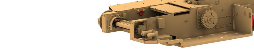
Fig. 82: Breaker power unit assembly
1 2 3
4
5 6
7 8
9
10 11
12
13
1. Sprocket 2. Gear reducer 3. Fan shroud 4. Taperlock bushing 5. Coupling 6. Taperlock bushing 7. Coupling cover 8. Electric motor 9. Connecting tube 10. Rotex coupling 11. Open loop load sense pump 12. Piggyback gear pump 13. Mounting base
How to assemble the breaker power unit
To assemble the breaker power unit proceed as follows (Fig. 82):
1. With the aid of a lifting device, slowly lift reducer onto mounting base and align mounting holes. Secure reducer with the eight (8) bolts, lockwashers and nuts to mounting base. Torque bolts to 460 ft-lb.
2. Slide reducer coupling element half onto reducer shaft.
3. Slide taper lock and shaft key onto reducer shaft. Locate reducer coupling element so that taper lock is flush with the end of the reducer shaft. Secure taper lock with the three (3) bolts supplied with taper lock. Torque bolts to 85 ft-lb.
4. Install end cap onto reducer shaft and secure with bolt and lockwasher. Torque bolt to 80 ft-lb.
5. Slide motor coupling element half onto motor shaft.
6. Slide taper lock and shaft key onto motor shaft. Locate motor coupling element so that motor shaft has .5 inch (12.7 mm).
Secure taper lock with the three (3) bolts supplied with taper lock. Torque bolts to 85 ft-lb.
7. Install end cap onto motor shaft and secure with bolt and lockwasher. Torque bolt to 80 ft-lb.
8. With the aid of a lifting device, slowly lift motor onto mounting base and align mounting holes and coupling halves. Secure reducer with the eight (8) bolts, lockwashers and nuts to mounting base. Torque bolts to 280 ft-lb.
9. Connect coupling with the twelve (12) bolts supplied with coupling.
10. Insert key into slot of motor shaft and slide motor coupling half onto motor shaft until shaft and coupling face are flush.
11. Tighten set screw in motor half of coupling.
12. Insert coupling element into motor half of coupling.
13. Align the 8 holes of connecting tube with motor and secure with the eight (8) bolts and lockwashers.
14. Slide pump half of coupling onto hydrostatic pump shaft until a .67” (17 mm) shaft end gap is acquired. Tighten the two (2) coupling half bolts.
15. With the aid of a lifting device, slowly lift hydrostatic pump and carefully align pump half and motor half of coupling. Secure pump to connecting tube with four (4) bolts and lockwashers.
Coupling spacing should be .18” (4.5 mm) after pump mounting bolts are tightened.
16. Align mounting holes and shaft of gear pump with hydrostatic pump and secure with four (4) bolts and lockwashers.
17. Install completed power unit onto machine. (See How to install the power unit)
18. Fill hydrostatic pump thru case drain port with system oil before running pump.
19. Check gearbox oil level. Oil should be visible in the lower sight glass only.