2 minute read
Dust suppression system .............................................. 5


dust suppression system regulator
dust suppression system pressure gauge WARNING! The pressure regulator should never be adjusted above 125 psi.
dust suppression system strainer
The dust suppression system regulator (Fig. 21) is located below the breaker power unit on the right side of the machine and is used to control the water pressure to the six spray nozzles located in the hose crossover tray over the breaker shaft. The water pressure to the nozzles is monitored by the dust suppression system pressure gauge (Fig. 21). To increase pressure, turn the regulator handle in (cw). To decrease pressure, turn the regulator handle out (ccw).
The dust suppression system pressure gauge (Fig. 21) is used to monitor the water pressure to the spray nozzles. The gauge should read between 5 and 125 psi.
The dust suppression system strainer (Fig. 21) is located below the breaker power unit on the right side of the machine and is used to filter particles from the mine water supply. The strainer should periodically be flushed to avoid becoming clogged. To flush the strainer, turn the ball valve handle, located on the branch of the strainer body, 90° in-line with the outlet. Allow to flush for approximately thirty seconds to one minute and then close the ball valve handle.
The water solenoid is located beside the regulator/strainer assembly and is used to control flow of water to the six spray nozzles located in the hosed crossover tray over the breaker shaft. The solenoid is controlled by a pressure transducer located in the hydraulic pressure gauge manifold beside the primary valve bank. When the “MAN/OFF/ AUTO” switch on the starter enclosure is set to “AUTO”, the “TRAM/ OFF/CONV” switch is set to “CONV”, and the hydraulic system pressure reaches 1,200 psi, the solenoid will open and allow water to flow through the water/oil cooler and then to the spray bars.
water solenoid
Fig. 21: Dust suppression system regulator and pressure gauge
Gauge Regulator Strainer Water solenoid
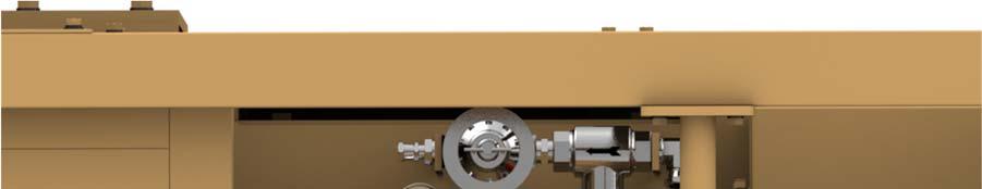
Machine wash down port Ball valve
photo eye pump motor controls
The photo eye sensors (Fig. 22) are used to control conveyor operation. When the conveyor is started, an adjustable timer with a default value of 2-1/2 minutes is initiated through the PLC. If, during this 2-1/2 minutes, a light is shone on either photo eye sensor for 4 continuous seconds, the conveyor timer is reset and the conveyor will continue running. If this action is not taken, the conveyor will shut down. When the conveyor shuts down, an adjustable timer with a default value of 15 minutes is activated. If, during this 15 minute period, neither photo eye sensor is activated, the breaker motor will shut down. If action is taken, the timers will reset and the conveyor will restart. Both timer settings are adjustable through the touch screen.
Note: A siren will sound upon initial start up and every time the conveyor is restarted after timing out. There will be a start up delay while the siren sounds.
Fig. 22: Photo eye sensors
Photo eye sensors