4 minute read
Head shaft sprockets ................................................... 5


Head shaft sprockets
The head shaft sprockets transmit the torque of the hydraulic motor to the conveyor chain assembly and are part of the head shaft assembly. As soon as the sprockets are worn, they must be replaced. Due to the high abrasion forces the chain sprockets are subject to a very high level of wear.
How to remove the head shaft sprockets
Note: If replacing one piece sprockets with split sprockets, torch the old sprockets off of the shaft and then follow Split sprocket installation procedure.
To remove the sprockets from the head shaft assembly (Fig. 68):
1. Remove the headshaft assembly from the feeder (see Head shaft removal in this chapter). 2. Remove the two (2) bearings from the headshaft. 3. Remove the two (2) set screws from each sprocket (it may be necessary to apply heat to loosen Loctite). 4. Slide both sprockets from the drive shaft. 5. Remove old keys. 6. Inspect all components of the drive shaft for wear and damage.
See the parts manual for your machine for a replacement parts list.
How to install the head shaft sprockets
To install the sprockets on the head shaft (Fig. 68):
1. Thoroughly clean and lubricate the drive shaft with Spec. 100-3 grease. 2. Insert one of the keys into the shaft keyway and slide first sprocket onto shaft (see Fig. 68 for location). It is customer preference on whether to weld the sprocket in place or not. See Fig. 79 for weld specifications. Apply Loctite 242 (blue) to screws and torque to 100 ft-lbs. 3. Insert the other key into the shaft keyway and slide second sprocket onto shaft (see Fig. 68 for location). It is customer preference on whether to weld the sprocket in place or not. See
Fig. 68 for weld spcifications. Apply Loctite 242 (blue) to screws and torque to 100 ft-lbs. 4. Install bearings on shaft (see Bearing installation procedure in this chapter). Note that the bearing housing must be installed on shaft so that the Taconite seal is facing the middle of the shaft. Only one of the bearings must have the internal spacer removed to allow the shaft to float and not be in a bind. 5. Install the drive shaft assembly in the feeder breaker. (See Drive shaft installation in this chapter.)
How to install the head shaft split sprockets
To install the split sprockets on the head shaft proceed as follows (Fig. 68):
IMPORTANT! Adhere to all weld specifications shown on Fig. 68. Failure to do so may result in sprocket failure and machine damage.
1. Release tension on the conveyor chain by removing shims from the conveyor chain take-up. (See Conveyor chain adjustment in this chapter).
2. Separate conveyor chain and fold back to clear drive shaft. (See
Conveyor chain replacement in this chapter).
3. Remove the two (2) sprocket guards located on the end of the feeder breaker.
4. Remove damaged sprockets and keys from head shaft. Old sprockets may require cutting to remove.
5. Thoroughly clean and degrease the drive shaft.
6. Insert key into shaft keyway.
7. Install both sprocket halves onto shaft and tack weld in place (see
Fig. 68 for location). Ensure sprocket alignment and proper spacing with conveyor chain.
8. Preheat sprocket weld joint to 600°F .
9. Weld sprocket halves together and do not exceed 800°F maximum interpass temperature. Ensure that the weld is smooth in the tooth area to prevent damage to the conveyor chanin bushings during chain operation.
10. If possible, cover sprocket with insulating blanket and allow weld to coolt to a maximum of 100°F before uncovering. If this is not possible, then post weld heat to 800°F.
11. Connect conveyor chain. (See Conveyor chain replacement in this chapter).
12. Adjust tension on the conveyor chain. (See Conveyor chain adjustment in this chapter).
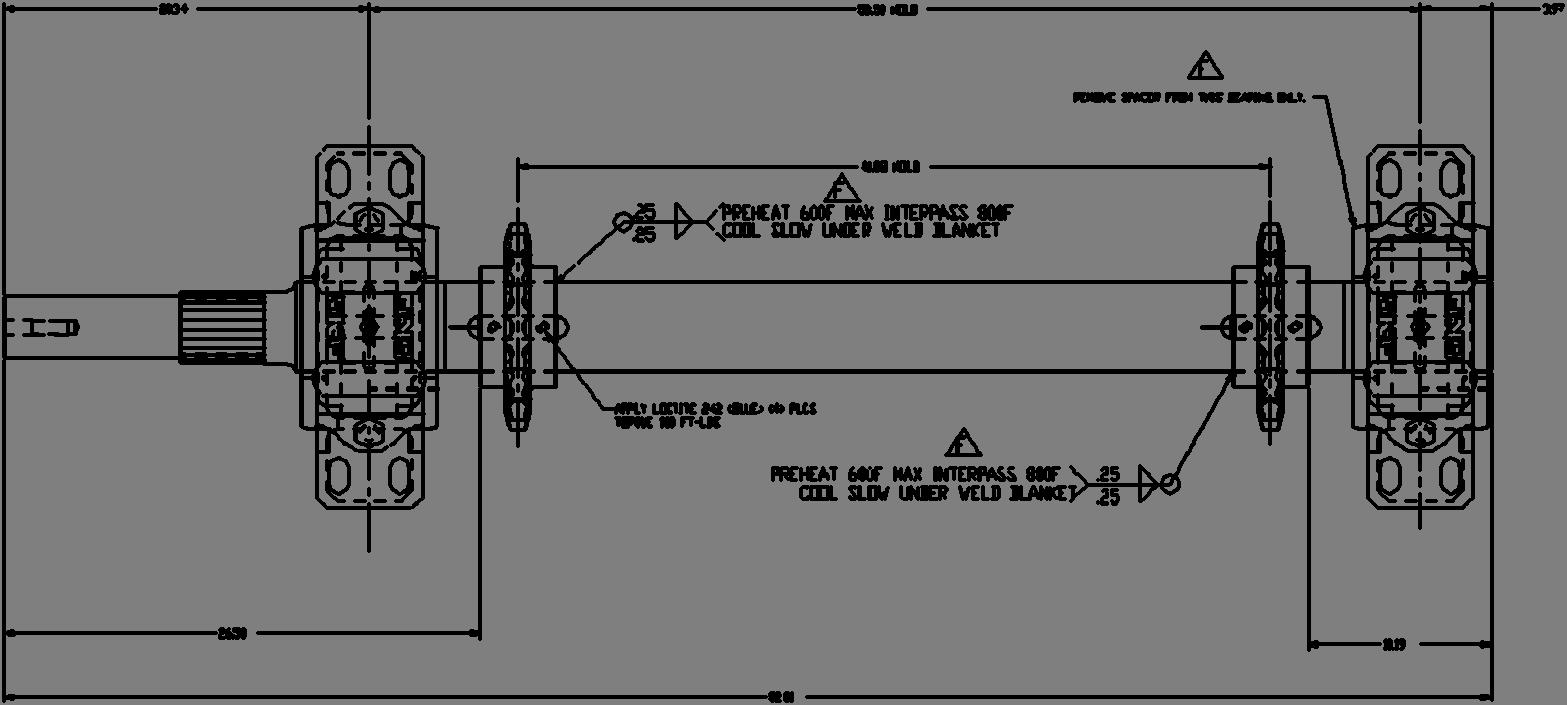
Fig. 68: Head shaft sprocket removal and installation
1 2 3
3/8 X 45° weld chamfer 3/8 X 45° weld chamfer
5
4
1. Sprocket guard 2. Head shaft 3. Conveyor chain 4. Bearing (2) 5. Sprocket (2) and key (2) Split sprocket (typical)
General notes:
1. Do not mix and match halves with other sprockets. 2. Install sprocket and keys on head shaft. 3. OK to temporarily tack weld sprocket halves to head shaft until welding is complete. 4. Blend and smooth welds to avoid chain roller damage.
Weld notes:
1. All welds chamfers are 1/2 X 45° except as noted above. 2. Preheat sprocket weld joint 600°F - 800°F. 3. Maintain preheat temperature during entire welding process. 4. Max interpass temperature not to exceed 800°F. 5. Use low hydrogen rod (E7018) or weld wire (Class E71T
Spec AWS A5.20). 6. Post weld heat sprocket joint 600°F - 800°F. 7. If possible/practical, bury sprocket in dirt or wrap with a welding blanket for a minimum of 8 hours or until sprocket temp reaches 100°F.
Taconite seal (optional)
Taconite seal (optional)
(optional for one piece sprockets)
(optional for one piece sprockets)