1 minute read
Breaker and breaker power unit assembly .................... 5


Breaker and breaker power unit assembly
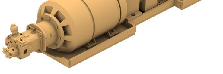
The breaker and breaker power unit (Fig. 36) are assembled with a bolt flange coupling so that they can be installed as individual assemblies. The power unit can be removed as a separate, complete assembly. To remove the breaker shaft, bolt flange coupling hardware must be removed..
There is an under speed sensor mounted on the right hand end of the breaker shaft that will shutdown the breaker drive motor in the event that breaker shaft slows below a preset speed.
NOTICE! In the event that a sudden jam occurs which could damage the gear reducer, the breaker is protected by a shear hub and shear pin.
Fig. 36: Breaker and breaker power unit assembly
1
5 2
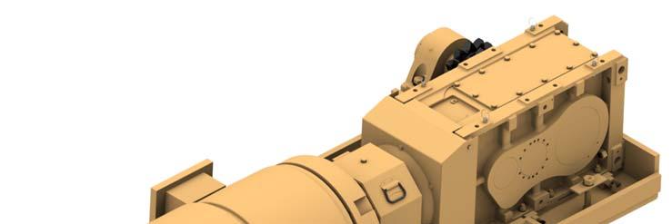
6 3
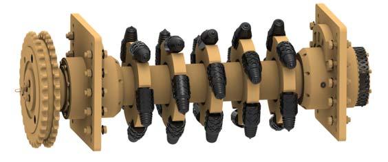
4 1. Gear reducer 2. Breaker motor 3. Breaker shaft 4. Under speed sensor 5. Shear hub 6. Shear pin