
8 minute read
Crawler assembly ........................................................ 5


Crawler assembly
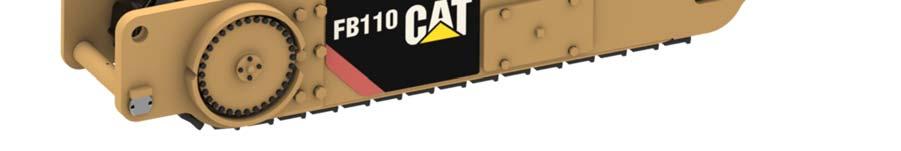
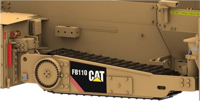
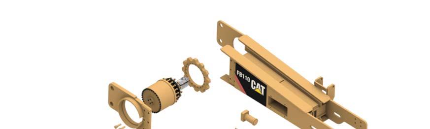
The crawler assembly (Fig. 77) consists of a take-up assembly and drive assembly that transmits torque to the crawler track via a hydraulic drive motor coupled to the tram drive torque hub. As soon as any component of the drive assembly is worn or damaged, the component must be replaced.
Fig. 77: Crawler assembly main components
1
4 3
5 2


1. Crawler track 2. Take-up roller assembly 3. Grease take-up (located behind cover) 4. Torque hub 5. Hydraulic motor
How to remove the crawler take-up assembly
To remove the crawler take-up assembly proceed as follows (Fig. 78):
1. Raise complete crawler assembly off ground and securely block under the machine. The machine must be securely supported off the ground with the crawler free to turn.
WARNING! You could be seriously injured or even killed by falling loads. Observe the safe working load of the lifting and blocking devices and keep a safe distance away from suspended loads.
2. Crawler track tension must be released (see Crawler track adjustment in this chapter.
3. Separate the crawler pads (see How to remove the crawler track assembly in this chapter) and fold pads back to clear take-up.
4. Securely block under the crawler frame.
5. Disconnect, tag and cap hydraulic hoses going to the tilt cylinder.
WARNING! Never disconnect a hydraulic hose if the circuit is pressurized or if there is a load on the circuit. If a hose is disconnected while the circuit is pressurized or a load is on the circuit, the load will fall causing damage to the machine or serious injury or death to you or other workers
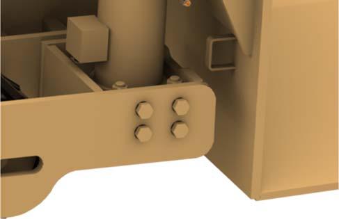
6. Remove the eight (8) bolts from the tilt cylinder mounting bracket.
7. Swing the tilt cylinder and mounting bracket free of the crawler frame.
8. Connect an additional pulling or lifting device (e.g. winch or lifting tackle with adequate load limit) to the take-up assembly and slowly pull the assembly out of the crawler frame.
WARNING! When using an additional pulling device (e.g. winch or lifting tackle with adequate load limit) for pulling the take-up, the connection could fracture under the load. You could be seriously injured or killed by the recoiling chain or cable. Use only approved lifting equipment for connecting pulling devices to the take-up.
9. Inspect all components for wear or damage.
How to install the crawler take-up assembly
To install the crawler take-up assembly proceed as follows (Fig. 78):
1. Remove old take-up assembly (see previous section, How to remove crawler take-up assembly).
WARNING! You could be seriously injured or even killed by falling loads. Observe the safe working load of the lifting devices and keep a safe distance away from suspended loads.
2. Inspect all components for wear or damage prior to assembly.
3. Clean all dirt and debris from inside crawler frame.
4. Attach appropriate lifting device to take-up assembly and slide assembly completely into the end of crawler frame.
5. Install and connect crawler and track pad assembly, see How to install the crawler track pad assembly in this chapter.
6. Swing the tilt cylinder and mounting bracket into crawler frame and secure with the eight (8) bolts, washers and nuts.
7. Connect hydraulic hoses to tilt cylinder.
8. Purge hydraulic system of air.
9. Adjust crawler track pad tension (see How to adjust crawler track pad tension in this chapter).
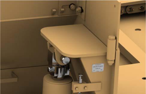
Fig. 78: Crawler take-up removal and installation
1
2
3
1. Crawler take-up 2. Tilt cylinder 3. Tilt cylinder mounting bracket
How to remove the crawler drive assembly
To remove the crawler drive assembly proceed as follows (Fig. 79):
1. Raise complete crawler assembly off ground and securely block under the machine. The machine must be securely supported off the ground with the crawler free to turn.
WARNING! You could be seriously injured or even killed by falling loads. Observe the safe working load of the lifting devices and keep a safe distance away from suspended loads.
2. Crawler track tension must be released (see Crawler track adjustment in this chapter).
3. Separate the crawler pads (see How to remove the crawler track assembly in this chapter) and fold pads back to clear sprocket.
4. Disconnect, cap and tag all hydraulic hoses to hydraulic motor.
5. Remove slotted nut, roll pin and washer from lift cylinder anchor pin.
6. Remove anchor pin from crawler frame and crawler guide weldment.
7. Remove the six (6) bolts and lock washers that secure the removable side plate to crawler frame and remove side plate.
8. Remove the twelve (12) bolts and lock washers that secure the torque hub to the crawler frame.
9. Attach an appropriate lifting device to the torque hub and slide complete assembly out of crawler frame.
10. Remove the four (4) bolts and lock washers that secure the hydraulic motor and adapter plate to the torque hub.
11. Attach an appropriate lifting device to the torque hub and slide complete assembly out of crawler frame.
CAUTION! Do not bump hydraulic motor or hydraulic motor fittings when removing the motor from the machine.
12. Remove the adapter plate and motor from the torque hub as an assembly.
13. If not replacing the hydraulic motor, it is not necessary to separate the adapter plate from the hydraulic motor. If replacing the hydraulic motor, remove the four (4) nuts and lock washers that secure the hydraulic motor to the adapter plate. And remove adapter plate.
14. Thoroughly clean and degrease the adapter plate mating face.
15. Remove the twenty (20) bolts and lock washers that secure the sprocket to the torque hub and separate hub and sprocket.
16. Inspect all components for wear or damage.
How to install the crawler drive assembly
To install the crawler drive assembly proceed as follows (Fig. 79):
1. Remove old crawler drive assembly (see previous section, How to remove crawler drive assembly).
WARNING! You could be seriously injured or even killed by falling loads. Observe the safe working load of the lifting devices and keep a safe distance away from suspended loads.
2. Inspect all components for wear or damage prior to installation.
3. Place sprocket onto torque hub and secure with the twenty (20) bolts and lock washers. Apply Loctite 242 (blue) to bolts and torque incrementally and evenly in a crossing pattern as follows.
■ Step 1: 70 ft-lb ■ Step 2: 140 ft-lb ■ Step 3: 210 ft-lb
4. Thoroughly clean and degrease the adapter plate and mating faces of the torque hub and hydraulic tram motor.
5. Apply Loctite 518 gasket eliminator or equivalent to the adaptor plate. Be sure to apply the sealant completely around all bolt holes to prevent leakage.
6. Place hydraulic motor gasket onto motor adapter plate.
7. Apply Loctite 518 to the second side of the motor gasket.
8. Install adapter plate and gasket onto hydraulic motor and secure with the four (4) nuts and lock washers. Apply Loctite 242 (blue) to nuts.
9. Apply Loctite 518 to the adapter plate gasket.
10. Place adapter plate gasket onto the adapter plate.
11. Apply Loctite 518 gasket eliminator or equivalent to the second side of the adaptor plate gasket. Be sure to apply the sealant completely around all bolt holes to prevent leakage.
12. Install motor and adapter plate assembly onto torque hub, being careful not to damage motor shaft or gasket. Secure with the (4) bolts and lock washers. Apply Loctite 242 (blue) to bolts and torque incrementally and evenly in a crossing pattern as follows:
■ Step 1: 25 ft-lb ■ Step 2: 50 ft-lb ■ Step 3: 70 ft-lb
13. If using a motor adapter plate that does not have the keepers already installed, weld four (4) keepers against the motor flanges to prevent motor movement.
14. Clean all dirt and debris from mounting area of crawler frame.
15. Attach an appropriate lifting device to the torque hub and slide complete assembly into crawler frame.
16. Secure torque hub assembly to frame with the twelve (12) bolts and lock washers. Apply Loctite 242 (blue) to bolts and torque incrementally and evenly in a crossing pattern as follows.
■ Step 1: 50 ft-lb ■ Step 2: 140 ft-lb ■ Step 3: 280 ft-lb ■ Step 4: 420 ft-lb
17. Connect hydraulic hoses to drive motor.
18. Install and connect crawler and track pad assembly (see How to install the crawler track pad assembly in this chapter).
19. Install the removable side plate and secure with the six (6) bolts and lock washers. Torque incrementally as follows.
■ Step 1: 300 ft-lb ■ Step 2: 600 ft-lb ■ Step 3: 905 ft-lb
20. Apply grease to anchor pin and slide anchor pin through crawler frame and tilt cylinder. Secure pin with slotted nut, washer and roll pin.
21. Purge hydraulic system of air.
22. Adjust crawler track pad tension (see How to adjust crawler track pad tension in this chapter).
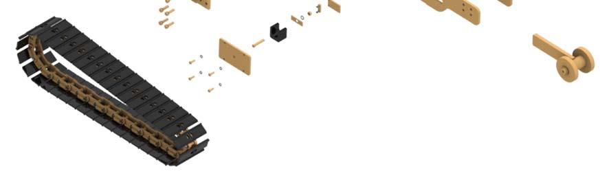
Fig. 79: Crawler drive disassembly and assembly
1 4 6
5 7 8 9
3
2
10
11 12

13
15 16
17 18
14 19
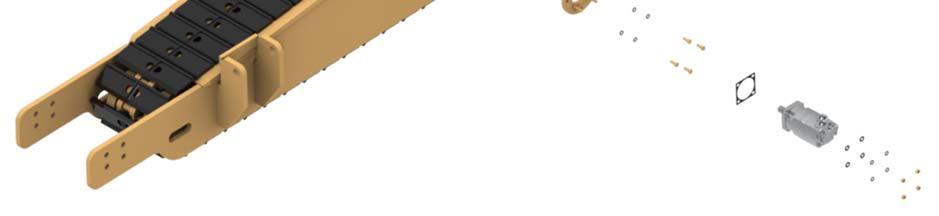
1. Crawler pad 2. Bolt (hex head) (6) & Washer (flat) (6) 3. Bushing 4. Side Plate 5. Torque hub 6. Cap screw (socket head) (20) & Washer (high collar lock) (20) 7. Cap screw (socket head) (12) &
Washer (high collar lock) (12) 8. Sprocket 9. Crawler frame 10. Bushing 11. Gasket (adaptor plate) 12. Plate (adaptor) 13. Keeper (hydraulic motor) 14. Washer (lock) (8) 15. Bolt (hex head) (4) 16. Gasket (hydraulic motor) 17. Hydraulic motor 18. Washer (flat) (4) 19. Nut (hex) (4)