3 minute read
Crawler track ............................................................... 5


Crawler track
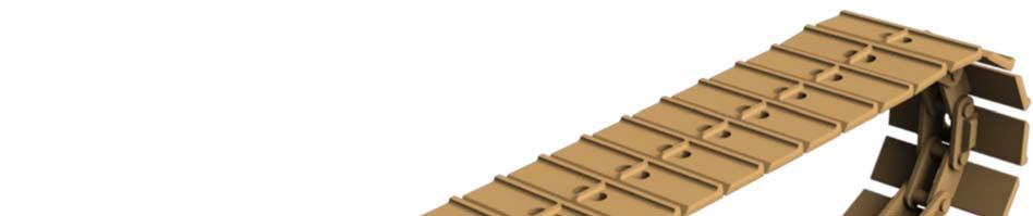
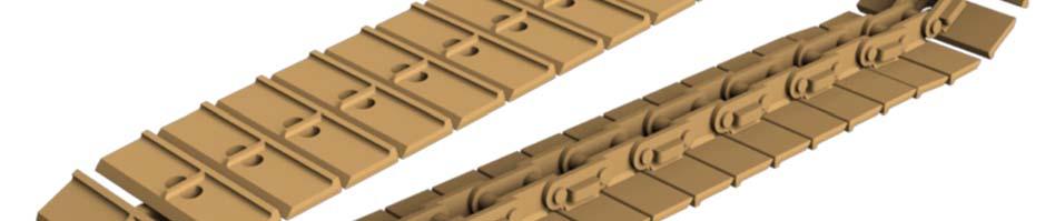
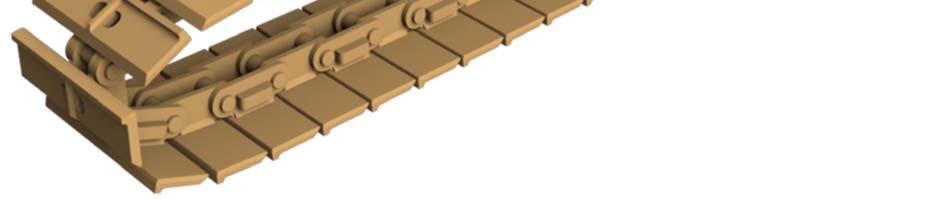
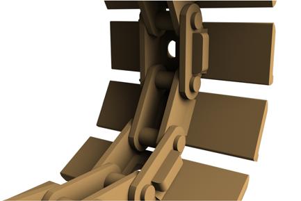
The crawler track (Fig. 76) assembly (left and right) carries the machine via torque received from the tram drive reducer. The crawler track is made up of two crawler pad links, one block link and one pin link, which alternatingly repeat along the entire pad loop. As soon as any component of the crawler track is worn the component or complete crawler track assembly must be replaced.
Each crawler track consists of the following main components:
1. Crawler pad block link 2. Crawler pad pin link 3. T-head cotter pin
Fig. 76: Crawler track main components
1 2
3
How to assemble the crawler track pads (Fig. 76)
To assemble the crawler track pads proceed as follows:
1. Lay crawler track pads on a flat surface.
2. Align pads with chain connecting holes centered.
3. Insert connector into center of crawler pad connecting holes.
4. Drive roll pin through connecting pin and bend end to secure.
5. Repeat above procedure for remainder of crawler pads.
How to remove the crawler track pad assembly (Fig. 76)
To remove the crawler track pad assembly proceed as follows:
1. Raise complete crawler assembly off ground and securely block under the machine. The machine must be securely supported off the ground with the crawler free to turn.
WARNING! You could be seriously injured or even killed by falling loads. Observe the safe working load of the lifting devices and keep a safe distance away from suspended loads.
2. Crawler track tension must be released (see Crawler track adjustment in this chapter).
3. Separate the crawler pads.
IMPORTANT! Heating or cutting connections with a torch or chisel may be required to ease the removal of T- pins.
a. Drive or cut roll pin from crawler pad connection using hammer and punch.
b. Separate crawler track assembly.
c. Connect an additional pulling or lifting device (e.g. winch or lifting tackle with adequate load limit) to either end of the crawler track assembly and slowly pull the crawler track completely out from under the machine.
WARNING! When using an additional pulling device for pulling the crawler track, the connection could fracture under the load. You could be seriously injured or killed by the recoiling chain or cable. Use only approved lifting equipment for connecting pulling devices to the crawler track.
4. Inspect the crawler drive sprocket and idler rollers for wear or damage. Replace if necessary.
How to install the crawler track pad assembly
To install the crawler track pad assembly proceed as follows (Fig. 76):
1. Remove old crawler track pad assembly (see previous section, How to remove crawler track pad assembly).
WARNING! You could be seriously injured or even killed by falling loads. Observe the safe working load of the lifting devices and keep a safe distance away from suspended loads.
2. Check to ensure that crawler track tension cylinder is completely retracted (see Crawler track adjustment in this chapter).
3. Slide crawler track pad assembly under crawler assembly.
4. Fold pad assembly over both ends of crawler assembly. Ensure that pad assembly meshes with drive sprocket and idler roller.
5. Connect crawler track pad assembly (see How to assemble crawler track pad assembly in this chapter for proper connection).
6. Adjust tension on the crawler track pad assembly (see Crawler track pad adjustment procedure in this chapter for proper adjustment).