3 minute read
Conveyor drive motor ................................................... 5


Conveyor drive motor
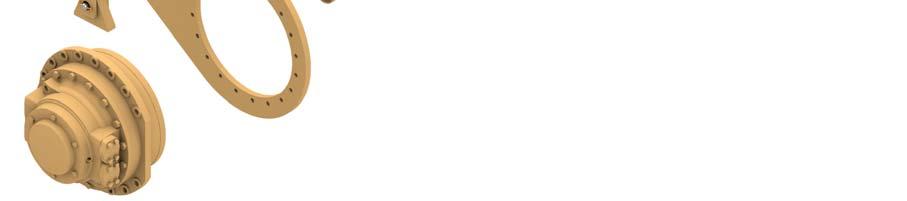
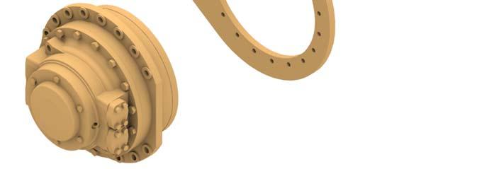
The conveyor drive motor (Fig. 85) transmits torque to the head shaft assembly. It is also part of the head shaft assembly. As soon as any component of the assembly is warn or damaged, the component must be replaced.
Fig. 85: Conveyor drive motor
1. Hydraulic motor 2. Headshaft coupling 3. Torque arm 1 3
2
How to remove the conveyor drive unit.
Whenever performing maintenance procedures, follow all safety regulations and be aware of the following:
WARNING! Before performing maintenance on the machine, the circuit breaker must be in the “OFF” position and the power should be disconnected at the main power source. Electrical shock and accidental machine movement can cause serious injuries or even death to you or the maintenance person.
WARNING! You could be seriously injured or even killed by falling loads. Observe the safe working load limits of lifting or devices and keep a safe distance from suspended loads.
To remove the conveyor drive motor proceed as follows (Fig. 86):
1. Disconnect, cap and tag all hydraulic hoses to the conveyor motor.
2. Remove the two (2) pins and cotter keys from the torque arm and remove torque arm connecting link.
3. Remove conveyor motor cover bolts and remove cover.
4. Remove torque mounting bolt located inside conveyor motor.
5. Attach an appropriate lifting device to two (2) of the conveyor motor torque arm mounting bolts and slowly slide the motor from the coupling and headshaft.
6. Disconnect lifting device and remove the torque arm mounting bolts.
7. Remove torque arm from conveyor motor.
8. Slide coupling from headshaft.
9. Inspect all components for wear or damage.
How to install the conveyor drive motor.
To install the conveyor drive motor proceed as follows (Fig. 86):
WARNING! Before performing maintenance on the machine, the circuit breaker must be in the “OFF” position and the power should be disconnected at the main power source. Electrical shock and accidental machine movement can cause serious injuries or even death to you or the maintenance person.
1. Apply a coat of mineral oil to the splines of the headshaft, coupling and conveyor motor. Do not use never seez.
IMPORTANT! Apply mineral oil or hydraulic oil to splines of head shaft and motor.
2. Slide coupling onto headshaft.
3. Install torque arm on conveyor motor with mounting bolts. Torque bolts to 400 ft-lb.
4. Remove conveyor motor cover bolts and remove cover.
5. Attach an appropriate lifting device to two (2) of the conveyor motor torque arm mounting bolts and slowly lift and slide the the motor onto the coupling and headshaft.
WARNING! You could be seriously injured or even killed by falling loads. Observe the safe working load limits of lifting or blocking devices and keep a safe distance from suspended loads.
6. Bolt conveyor motor to headshaft with torque mounting bolt located inside conveyor motor. Torque bolt to 280 ft-lb.
7. Install conveyor motor cover with cover bolts. Torque bolts to 60 ftlb.
8. Install torque arm connecting link with the two (2) pins and cotter keys.
9. Connect all hydraulic hoses to the conveyor motor.
10. Purge hydraulic system of air.
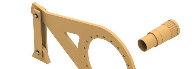
Fig. 86: Conveyor drive motor removal and installation
Connecting link
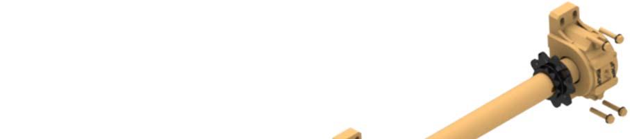
Cover bolts (torque to 60 ft-lb) Pin and cotter key (2 places)

Torque arm Head shaft
Coupling
Mounting bolt (torque to 280 ft-lb - under cover)
Mounting bolts (torque to 400 ft-lb)