71
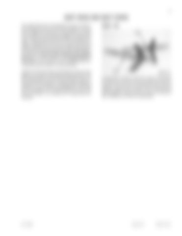
SHIFT RODS AND SHIFT FORKS The original third-fourth rod assembly will not be re-used. It will be replaced by new parts from the update kit. The new fork will appear the same as the original third-fourth except for the machining on the legs that engage the synchronizer collar. Using the original third-fourth shift rod assembly as a pattern, assemble the new rod, fork, and roll pin from the update kit. Note the new rod may have different machining on the ungrooved end and may have two cross drilled holes for the fork roll pin. Use the hole closest to the detent grooves. The hole closest to the ungrooved end corresponds to the location for the first-second shift fork. These parts may be common in future production.
STEP 310
Inspect the first-second shift rod assembly for abnormal wear patterns on the shift rod diameter and detent grooves. The fork should be tight on the rod. Check the fingers on the firstsecond shift fork for abnormal or excessive wear. Replace as necessary. It is not necessary to disassemble the first-second shift rod assembly if it is in good condition for re-use. Roll pins are included in the uoverhaul kit if replacements are necessary.
1st/2nd
Bur 7-54022
3rd/4th
BP95F132
If disassembly is required, remove the roll pins and separate the shift forks from the shift rods. Make sure that you remember how the parts are assembled and which parts go together. Except for the roll pins, none of the par ts are interchangeable. Inspect all parts for burrs and excessive wear. Assembly is the reverse of disassembly.
Issued 10-97
Printed in U.S.A.


