12 minute read
Assembly of the Input Shaft

from Case L-Series Loader Backhoe Transmission Update Kits Installation Instructions Manual 7-54022 - PDF

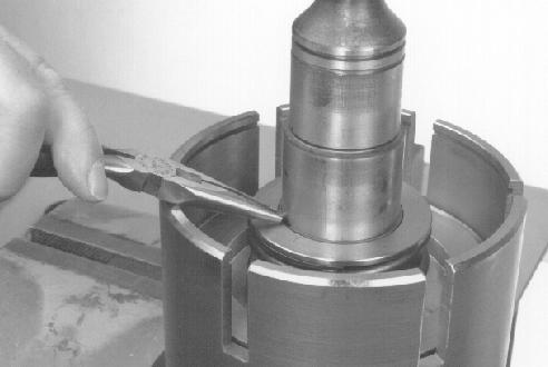
STEP 148
STEP 151
BP95F127 Use clean transmission oil to lubricate the sealing rings. Install a sealing ring in each piston. New pistons are provided in the update kit. New seals are provided in the overhaul kit.

STEP 149
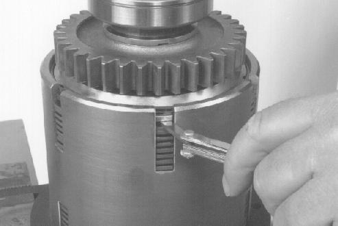
Install the spring.
STEP 152
BP95F207

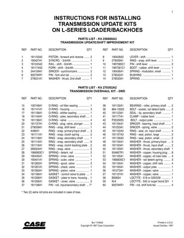
BP95F126 Install the sealing ring on the input shaft in the forward clutch housing. This seal ring is provided in the overhaul kit. Lubricate the input shaft and inside of housing with clean transmission oil.
STEP 150
BP95F208 Install the retainer plate. The side which has a raised area around the bore goes down. The side which has the groove around the bore goes up. The outer edge of the snap ring must fit in this groove after the parts are assembled.
BP95F206 Use clean transmission oil to lubricate the edge and the bore of the piston. Install the piston.

BP95F209 Install the top piece of the CAS-2379 special tool. Use the three threaded rods and nuts to fasten the two pieces together. Tighten the nuts evenly to compress the spring just enough to get access to the snap ring groove in the input shaft. Install a new snap ring from the overhaul kit. Loosen the nuts to relieve the spring tension and remove the CAS2379 special tool. Make sure that the outer edge of the snap ring is seated in the groove in the retainer plate.

STEP 154
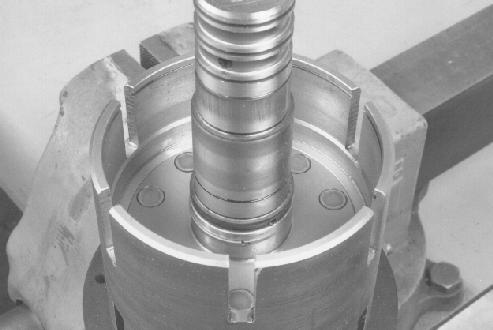
BP95F211 Use clean transmission oil to lubricate a new thrust washer from the overhaul kit. Install the thrust washer so that the notch in the inner edge fits over the pin. Make sure that the side with the oil grooves is up.
STEP 156

Install a new pin from the Overhaul Kit. BP95F210 BP95F213 Use clean transmission oil to lubricate the needle bearings. Install the first needle bearing.

STEP 157

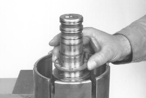
Install a new spacer from the overhaul kit. BP95F214

Install the second needle bearing.
STEP 159
BP95F215
Install one friction disc. BP95F234
NOTE: If you will be using new friction discs, soak the friction discs in clean transmission oil for at least an hour before assembly. If you are using the old friction discs, make sure that the friction surfaces are coated with transmission oil before assembly.
STEP 162

BP95F232 To assemble the clutch pack, start with the gear on the bench. Install the end cover so that the flat side is up.

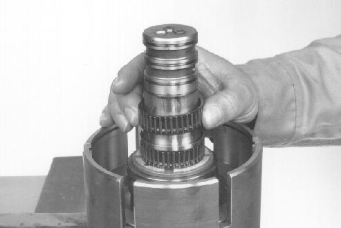
STEP 160
Install TWO steel discs. BP95F233 Install one steel disc. BP95G003

STEP 163
Repeat steps 160 and 161 until all the clutch discs are installed. The clutch pack will finish with one steel disc instead of two as are at the other end. The assembled
clutch pack should contain eight steel discs
and six friction discs.
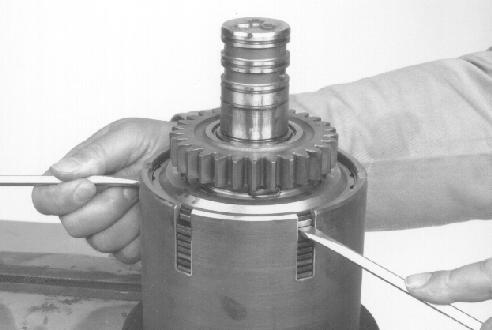
BP95F226 Make sure that the tabs on all the steel discs are aligned with each other. Hold the clutch pack together so that the parts do not move and rotate the clutch pack so that the clutch discs are down. Put the clutch pack on the clutch housing as shown so that the tabs on the steel discs are almost ready to start into the slots in the clutch housing.
STEP 165
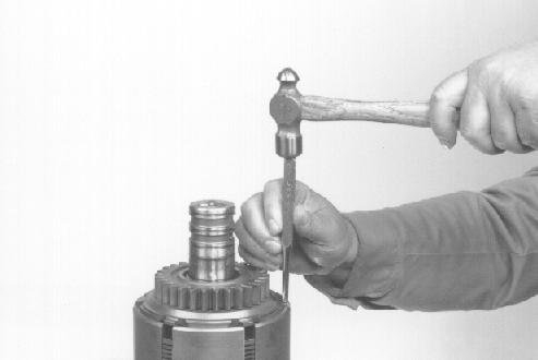
BP95F228 When all the clutch discs are down, and the gear is down as far as the end cover will permit, remove the screwdrivers. Use a punch and a hammer to move the end cover down evenly just far enough to get access to the snap ring groove in the clutch housing.
STEP 167

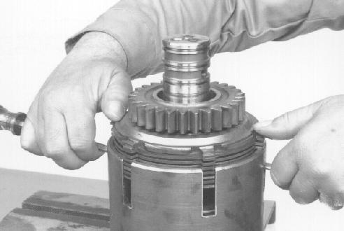
BP95F227 Use two screwdrivers in opposite slots in the clutch housing to support the clutch pack as you start the clutch pack into the clutch housing. Move the clutch pack down slowly and evenly, making sure that all the tabs are going into the slots. Also make sure that the gear moves down with the clutch pack. Install a new retaining ring from the overhaul kit. BP95F229
STEP 168
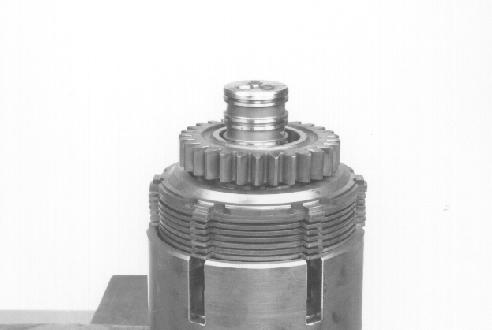
BP95F230 Use two screwdrivers to move the end cover up until the end cover is against the snap ring. There is a recess in the outer edge of the end cover. When the end cover is up all the way, the inner edge of the snap ring will fit in this recess.

Install a new pin from the overhaul kit.

STEP 170
BP95F109
Install a new snap ring from the overhaul kit.
STEP 173
BP95F105
BP95F108 Use clean transmission oil to lubricate the thrust washer. Install the thrust washer so that the notch in the inner edge fits over the pin. Make sure that the side with the oil grooves is down.

STEP 171
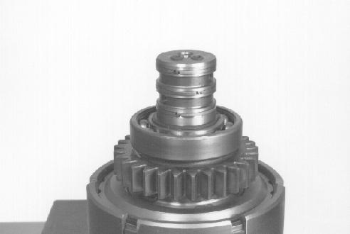
BP95F231 Use an acceptable driver or press to force the bearing onto the input shaft until the bearing makes contact with the thrust washer. BP95F104 Use clean transmission oil to lubricate three new sealing rings from the overhaul kit. Install the three sealing rings on the input shaft. Turn the sealing rings on the input shaft so that the connecting ends of each sealing ring are 120 degrees from the connecting ends of the other two sealing rings.

NOTE: The connecting ends of the sealing rings in the photo above are shown aligned so that the sealing rings can be seen clearly.
NOTE: New sealing rings provided in the overhaul kit may be “unplated” or maybe plated with a material that does not exhibit the flaking problem experienced with earlier sealing rings. Whether plated or unplated, lubricate the sealing rings and their mating bores generously with clean transmission fluid during assembly.

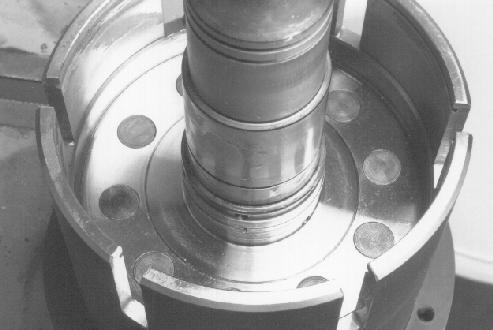
BP95F102 Put the input shaft in the bottom piece of the CAS-2379 special tool so that the reverse clutch housing is up. Lubricate the shaft and inside the clutch housing with clean transmission oil. Install a new sealing ring from the overhaul kit on the input shaft in the reverse clutch housing.
STEP 175
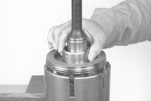
BP95F656 Install the retainer plate. The side which has a raised area around the bore goes down. The side which has the groove around the bore goes up. The outer edge of the snap ring must fit in this groove after the parts are assembled.
STEP 178

BP95F235 Use clean transmission oil to lubricate the edge and the bore of the new piston and seal. Install the piston.
STEP 176
BP95F237 Install the top piece of the CAS-2379 special tool. Use the three threaded rods and nuts to fasten the two pieces together. Tighten the nuts evenly to compress the spring just enough to get access to the snap ring groove in the input shaft. Install a new snap ring from the overhaul kit. Loosen the nuts to relieve the spring tension and remove the CAS2379 special tool. Make sure that the outer edge of the snap ring is seated in the groove in the retainer plate.
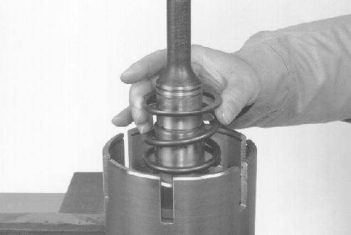
Install the spring. BP95F236
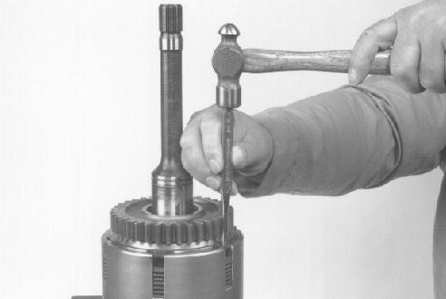
BP95F239 Install a new pin from the overhaul kit. Push the pin until it bottoms out in the hole.
STEP 180
BP95F232 To assemble the clutch pack, start with the gear on the bench. Install the end cover so that the flat side is up.
STEP 183
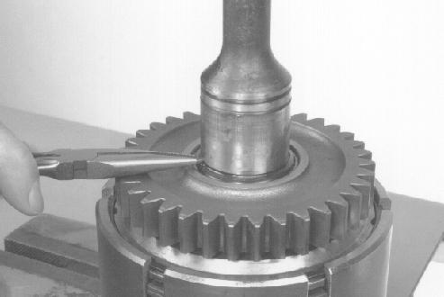
BP95F240 Use clean transmission oil to lubricate a new thrust washer from the overhaul kit. Install the thrust washer so that the notch in the inner edge fits over the pin. Make sure that the side with the oil grooves is up.

STEP 181
Install TWO steel discs.
STEP 184
BP95F233

BP95F241 Use clean transmission oil to lubricate the needle bearings. Install the needle bearings. Install one friction disc. BP95F234

NOTE: If you will be using new friction discs, soak the friction discs in clean transmission oil for at least an hour before assembly. If you are using the old friction discs, make sure that the friction surfaces are coated with transmission oil before assembly.

Install one steel disc. BP95G003

STEP 186
Repeat steps 183 and 184 until all the clutch discs are installed. The clutch pack will finish with one steel disc instead of two as are at the other end. The assembled
clutch pack should contain eight steel discs
and six friction discs.
STEP 187
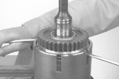
BP95F243 Use two screwdrivers in opposite slots in the clutch housing to support the clutch pack as you start the clutch pack into the clutch housing. Move the clutch pack down slowly and evenly, making sure that all the tabs are going into the slots. Also make sure that the gear moves down with the clutch pack.
STEP 189
BP95F242 Make sure that the tabs on all the steel discs are aligned with each other. Hold the clutch pack together so that the parts do not move and rotate the clutch pack so that the clutch discs are down. Put the clutch pack on the clutch housing as shown so that the tabs on the steel discs are almost ready to start into the slots in the clutch housing. BP95F244 When all the clutch discs are down, and the gear is down as far as the end cover will permit, remove the screwdrivers. Use a punch and a hammer to move the end cover down evenly just far enough to get access to the snap ring groove in the clutch housing.

STEP 190

BP95F245
STEP 191

BP95F246 Use two screwdrivers to move the end cover up until the end cover is against the snap ring. There is a recess in the outer edge of the end cover. When the end cover is up all the way, the inner edge of the snap ring will fit in this recess.
STEP 192 3
2
1
BP95F248 Use clean transmission oil to lubricate a new thrust washer (1) from the overhaul kit. Install the thrust washer (1) so that the notch in the inner edge fits over the pin. Make sure that the side with the oil grooves is down. Install the spacer (2). Put the bearing (3) into position so that the snap ring groove on the outside of the bearing (3) is up. Use an acceptable driver or press to force the bearing (3) onto the input shaft until the bearing (3) makes contact with the spacer (2).
STEP 194

Install a new pin from the overhaul kit. BP95F247
Install a new snap ring from the overhaul kit.
STEP 195
BP95F077

BP95F076 Use clean transmission oil to lubricate the sealing ring. Install a new sealing ring from the overhaul kit on the input shaft.
Measure the clutch disc clearance for each clutch assembly. The end cover must be all the way up against the snap ring. Use a feeler gauge to measure the distance between the end cover and the first metal disc. The distance must be 0.09 to 0.17 inch (2.3 to 4.3 mm). If the distance is not within specification, the clutch is probably assembled wrong. Clutch plate wear will not cause the distance to be outside the specification.
7
BP95F249
6
5 4
2 1 3
2 1
REVERSE FORWARD
1.Forward Clutch Passage 3.Forward Gear 5.Reverse Clutch Pack 7.Input Shaft 2.Reverse Clutch Passage 4.Forward Clutch Pack 6.Reverse Gear
BT95G174
STEP 197
See the illustration above. Apply compressed air of approximately 90 psi (620 kPa) to the forward clutch passage. Listen to hear the forward piston moving to lock the forward clutch pack. Try to move the forward gear. The forward gear must not turn on the input shaft. Try to move the reverse gear. The reverse gear must turn freely on the input shaft. If the clutches do not operate correctly, disassemble the clutches to find and correct the problem.
STEP 198
See the illustration above. Apply compressed air of approximately 90 psi (620 kPa) to the reverse clutch passage. Listen to hear the reverse piston moving to lock the reverse clutch pack. Try to move the reverse gear. The reverse gear must not turn on the input shaft. Try to move the forward gear. The forward gear must turn freely on the input shaft. If the clutches do not operate correctly, Disassemble the clutches to find and correct the problem.