7 minute read
Assembly of the Transmission Control Valve

from Case L-Series Loader Backhoe Transmission Update Kits Installation Instructions Manual 7-54022 - PDF

STEP 431
1
1
1
1
2
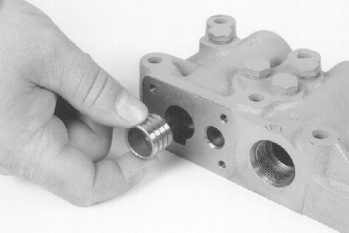
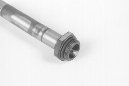
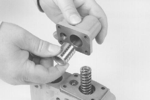
Use clean transmission oil to lubricate the flow divider piston. Install the flow divider piston in the opposite end of the bore. The closed end of the flow divider piston must be toward the plug in the end of the bore so that the spring will fit inside the open end of the piston..
STEP 434
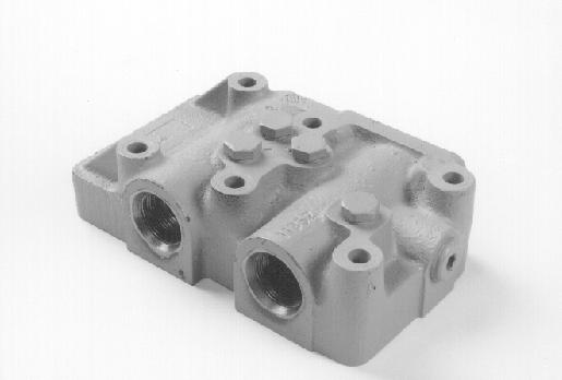
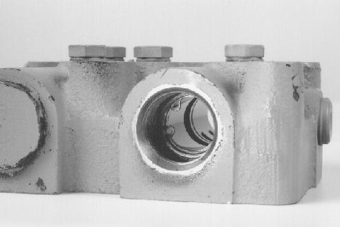
BP95F320 Install the four hex head plugs (1) and the Allen head plug (2) using the new copper washers provided in the overhaul kit. Lubricate the bores of the valve body with clean transmission oil.

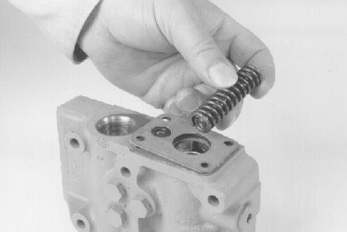
STEP 432
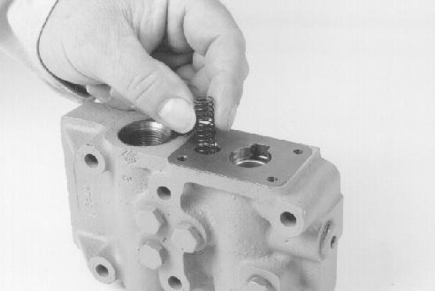
BP95F314 Install the new spring from the overhaul kit in the bore.
STEP 435

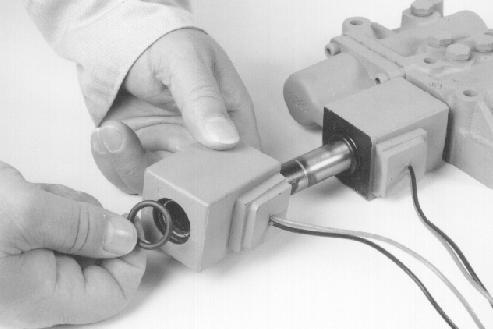
BP95F316 Install a new snap ring from the overhaul kit in the bore as shown.
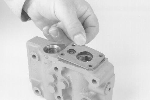
STEP 433
Install the flow divider shaft in the bore.
STEP 436
BP95F311

BP95F313
BP95F312
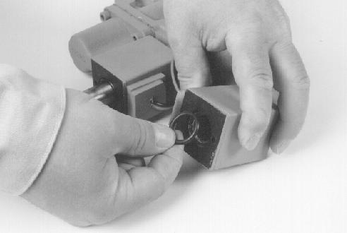
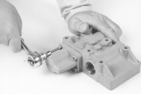
Put a new snap ring into the bore. Use a small screwdriver or punch to push the snap ring and the flow divider shaft down against the spring tension until the snap ring is seated in the snap ring groove.
STEP 437

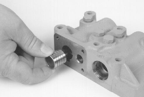
BP95F310 Use clean transmission oil to lubricate the inner modulation piston. Install the inner modulation piston so that the end with the deeper bore is toward the outside of the control valve body.
STEP 438

BP95F322 Install the new spring from the overhaul kit in the small bore.
STEP 439
Install the ball on top of the spring.
STEP 441
BP95F324
BP95F325 Put the plate into position so that the small hole is over the ball. Position the plate so that the the radius on the edges of the holes and plate are next to the valve casting and the check ball.
STEP 442
Install a new gasket from the overhaul kit. BP95F323 BP95F330 Put the remaining new gasket into position on top of the plate.

4

2
3 1
BP95F329 Put the pin (1) and the new small spring (2) from the update kit inside the medium spring (3). Then put the medium spring (3) inside the large spring (4).
STEP 444
1
BP95F331 Install the spring and pin assembly into the bore so that the end which has the pin (1) is toward the inside of the control valve body.
STEP 445 STEP 446
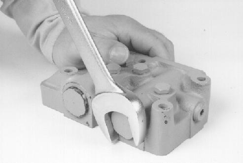
BP95F300 Install the four Allen head screws to fasten the modulation cover to the control valve body. Tighten the Allen head screws to a torque of 97 pound-inches (11 Nm).
STEP 447
BP95F334 Install a new O-ring from the overhaul kit on the solenoid plunger. Use clean transmission oil to lubricate the O-ring.
BP95F332 Use clean transmission oil to lubricate the outer modulation piston and bore of the cover. Install outer modulation piston in the modulation cover so that the closed end of the outer modulation piston is toward the modulation cover. Install the modulation cover on the control valve body so that the outer modulation piston fits over the spring and pin assembly.
1

2
3
4
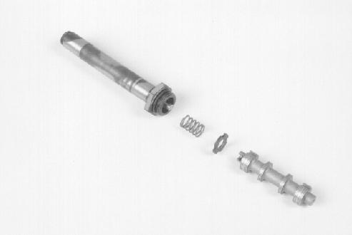
BP95F333 Assemble the solenoid plunger (1), a new spring (2), a new spring spacer (3), and the forward/reverse spool (4) as shown above. One side of the spring spacer (3) has a chamfer in the bore. Install the spring spacer (3) so that the chamfer is toward the forward/reverse spool (4). The new spring and spacer are included in the overhaul kit.
STEP 449
BP95F299 Install the solenoid plunger and the forward/reverse spool in the control valve body. Make sure that the end of the forward/ reverse spool goes into the spring spacer which was installed in the opposite end of the bore in step 433.
STEP 451
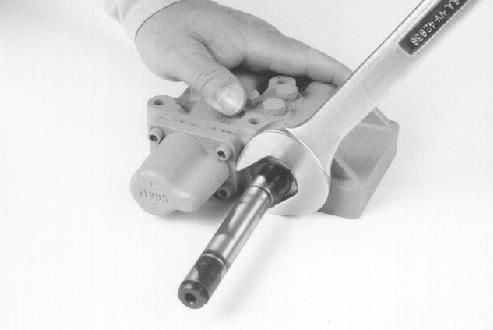
BP95F335 Use a small screwdriver to push down the spring as shown so that you can engage the notched end of the forward/reverse spool with the post on the end of the solenoid plunger. When the notched end and the post are fully engaged, release the spring to hold the forward/reverse spool in position. BP95F297 Tighten the solenoid plunger to a torque of 204 pound-inches (23 Nm).

STEP 452

BP95F318
Install the new spring spacer provided in the overhaul kit in the bore as shown. One side of the spring spacer has a very small chamfer on the edge of the inside diameter. Install the spring spacer so that the chamfer is toward the inside of the control valve body. Visually check that the end of the spool protrudes through the hole in the spring spacer. NOTE: It may be easier to position the spring spacer (step 452) and to install the spring (step 453) if the valve is positioned vertically with the bore facing up.
STEP 453
BP95F319 Install the new spring provided in the overhaul kit in the bore.

STEP 454
BP95F315 Install a new O-ring on the plug. Use clean transmission oil to lubricate the O-ring. Install the plug in the bore. NOTE: Steps 456 through 458 are necessary only if the two solenoids were separated (or one or both are being replaced) at the time of disassembly.
STEP 456
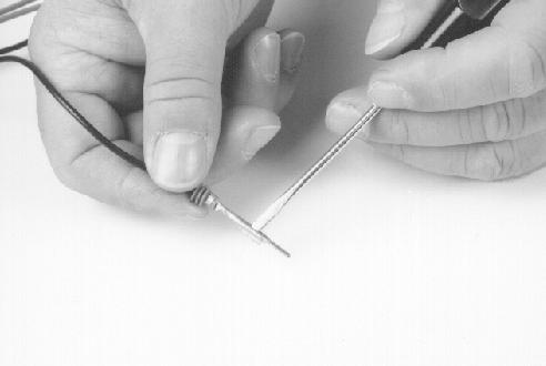
BP95F317 Install a new O-ring from the overhaul kit on the plug. Use clean transmission oil to lubricate the O-ring. Install the plug in the bore. BP95F298 Before inserting a terminal in the connector, use a small screwdriver to push the locking tab out slightly so that the locking tab will engage the plastic tab in the connector when you insert the terminal.


BP95F296 Push each terminal into the connector until the locking tab and the plastic tab engage, locking the terminal into the connector.

STEP 458
BP95F294

BP95F293 After all the terminals are in the connector, install the retainer on the rear of the connector. BP95F291 Install new O-rings from the overhaul kit at each end of the solenoid coil which goes next to the control valve body. Use clean transmission oil to lubricate the O-rings.

STEP 460

Install the solenoid coil on the solenoid plunger. BP95F290
STEP 463


BP95F289
BP95F287
BP95F286 Install the remaining solenoid coil on the solenoid plunger. Recheck that the solenoids are in the same position and orientation as when they were removed.
Install new O-rings at each end of the remaining solenoid coil. Use clean transmission oil to lubricate the O-rings.
STEP 462
BP95F285
Install a new copper washer from the overhaul kit.
STEP 464
BP95F284 Install the nut. Tighten the nut to a torque of 156 poundinches (17.6 Nm).