12 minute read
Assembly of the Secondary Shaft

from Case L-Series Loader Backhoe Transmission Update Kits Installation Instructions Manual 7-54022 - PDF

NOTE: Before each gear is installed on the secondary shaft, make sure that the bore of the gear and the outside diameter of the secondary shaft are completely lubricated with clean transmission oil.
NOTE: When you install snap rings on the secondary shaft, make sure that the ends of each snap ring are seated in the snap ring groove. Do not install a snap ring so that the ends extend into an axial slot on the secondary shaft.
NOTE: Before starting to assemble the secondary shaft, make the following measurement with a vernier caliper.
DIM A STEP 240
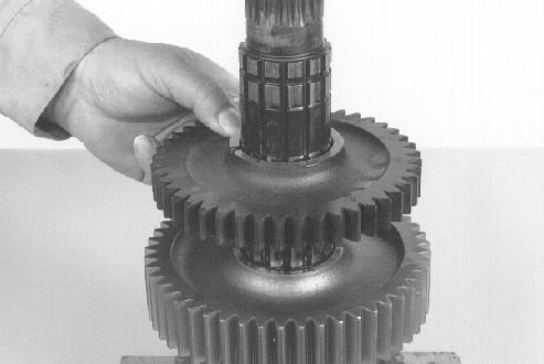
Install first gear.
STEP 241
BP95F159
1 & 2 GEARS END 3 & 4 GEARS END
MEASUREMENT ___________________
Record this measurement as it will be used to determine the correct thrust washer to install at step 279.

STEP 239
BP95F162 Install a new snap ring from the overhaul kit. Position the ends of the snap ring as previously noted.
STEP 242

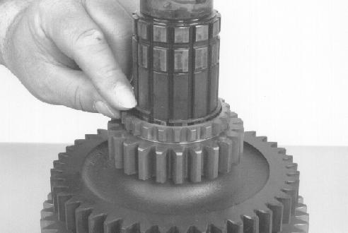
BP95F161 Put the secondary shaft on the bench so that the first-second gear end is up. You can use the output flange as a stand to hold the secondary shaft in position. Install a new snap ring from the overhaul kit as shown.

Install the spacer. BP95F157

3 1
2
2 2 3
1
3 1
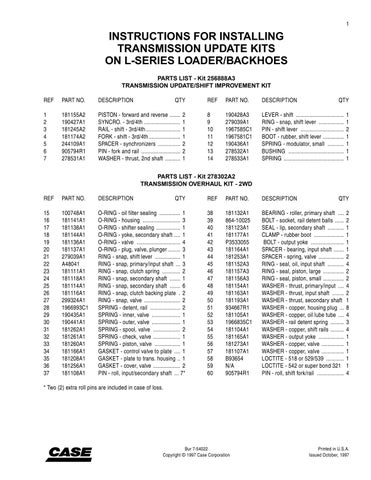
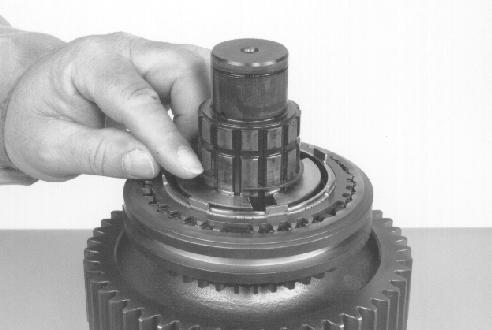
BP95F169 This photo shows the correct relationship between the hub and the sleeve for assembly of the first-second synchronizer. The tabs (1) in the inside diameter of the sleeve fit into the small recesses (2) in the outside diameter of the hub. The large recesses (3) in the hub are for the detent assemblies, which are not yet installed.
STEP 244
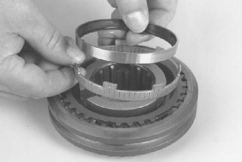
BP95F173 Use a punch or screwdriver to push the balls into the blocks and to push the blocks down so that the balls are on the flat faces of the teeth, but not into the detent grooves. When all the balls are in position, push the hub and the blocks down until the balls move into the detent groove.
STEP 246

BP95F172 This photo is for reference only. It shows the correct positions of the hub, the sleeve, the springs, the blocks, and the balls prior to final assembly.The springs are installed in the hub, and the blocks are on the springs. The blocks are not yet pushed down into the sleeve and are holding the hub up out of sleeve. The balls are loose in the recesses of the blocks.

NOTE: Position each ball, block, and spring in the assembly one-at-a-time and complete the installation of the parts as shown in step 245 before positioning the next set of parts. Otherwise you risk loosing some of the parts. BP95F165 Install the tapered friction ring on the synchronizer assembly.
STEP 247
2
1
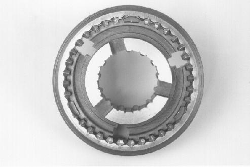
BP95F164 Lubricate both rings liberally with clean transmission oil and install the bronze ring (1) and the steel ring (2) as shown.
BP95F163 Install the synchronizer ring as shown. The flat sides of the teeth must be up and the tapered side of the teeth must be towards the large sliding sleeve.

STEP 249
Position the top synchronizer ring on top of the assembly. Pick the assembly up and align the teeth on the top ring with the teeth on the inside of the sliding sleeve. Press the sliding sleeve up until it engages the teeth on the top ring. This will require enough effort to overcome the force of the detent springs and balls. When the ring and sleeve are fully engaged, the detent should hold the sleeve in this position. Press the sleeve back down to the neutral position, turn the synchronizer over, and repeat the above check with the bottom synchronizer ring. If the sleeve does not engage the teeth readily or does stay in place when moved to any of the three positions, it is an indication that the synchronizer was not assembled correctly or that damaged parts were reassembled into the synchronizer. First check that the top and bottom rings are positioned correctly (note step 248). If this is not the problem, disassemble and determine the cause.
STEP 252
Remove the top synchronizer ring.
STEP 253
BP95F165 Turn the synchronizer assembly over and install the tapered friction ring on the other side.
STEP 250
2
1
BP95F156 Install the synchronizer assembly without the top synchronizer ring.
NOTE: There is a groove in the bore at one end of the synchronizer hub. The synchronizer assembly must be installed so that the groove is down.
BP95F164 Lubricate both rings liberally with clean transmission oil and install the bronze ring (1) and the steel ring (2) as shown.

Install a new snap ring from the overhaul kit.
STEP 255
BP95F174
Install a new pin from the overhaul kit.
STEP 258
BP95F151

BP95F154 Install the top synchronizer ring so that the flat sides of the teeth are up and the tapered side of the teeth face down toward the sliding sleeve.
STEP 256
BP95F150 Use clean transmission oil to lubricate a new thrust washer from the overhaul kit. Install the thrust washer so that the notch in the inner edge fits over the pin. Make sure that the side with the oil grooves is down.
STEP 259
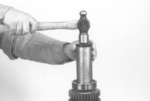
BP95F153 Install the spacer and second gear. The teeth in the inside diameter of the spacer must engage the teeth on the bottom of second gear before second gear is installed. BP95F176 Use an acceptable driver or press to force the bearing race from one of the new roller bearing sets in the overhaul kit onto the secondary shaft until the bearing race makes contact with the thrust washer.

Install a new snap ring from the overhaul kit.

STEP 261
BP95F146 BP95F179 Install a new snap ring from the overhaul kit. The snap ring must be in the lowest groove. There is a lubrication groove just above the snap ring groove. If you install the snap ring in the lubrication groove, you will not be able to assemble the other parts correctly.
STEP 263

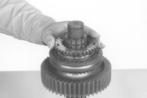
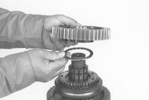
BP95F144 Turn the secondary shaft over so that second gear is at the bottom. Use blocks or a soft jawed vise to support the secondary shaft. Install the four-wheel drive gear, if equipped. On two-wheel drive transmissions, there is a spacer here instead of the gear. If the transmission is a twowheel drive, install the spacer. Install fourth gear.
STEP 264
BP95F142
Install a new snap ring from the overhaul kit. BP95F180
Install the spacer. BP95F157
NOTE: If the new third-fourth synchronizer in the update kit is pre-assembled, remove the rings (reference steps 219, 223 through 227) leaving only the hub, shift sleeve, and detent parts intact.. Verify that the blocks and balls are in the correct positions and fully engaged into the detent groove according to step 268. Reassemble according to steps 269 through 274.
STEP 266
3 1
2
2 2 3
1
3 1
BP95F169 This photo shows the correct relationship between the hub and the sleeve for assembly of the third-fourth synchronizer. The tabs (1) in the inside diameter of the sleeve fit into the small recesses (2) in the outside diameter of the hub. The large recesses (3) in the hub are for the detent assemblies, which are not yet installed. BP95F172 This photo is for reference only. It shows the correct positions of the hub, the sleeve, the springs, the blocks, and the balls prior to final assembly.The springs are installed in the hub, and the blocks are on the springs. The blocks are not yet pushed down into the sleeve and are holding the hub up out of sleeve. The balls are loose in the recesses of the blocks.
NOTE: Position each ball, block, and spring in the assembly one-at-a-time and complete the installation of the parts as shown in step 245 before positioning the next set of parts. Otherwise you risk loosing some of the parts.
STEP 268
BP95F173 Use a punch or screwdriver to push the ball into the block and to push the block down so that the ball is on the flat faces of the teeth, but not into the detent grooves. Repeat this for the other two sets of detent parts. When all the balls are in position, push the hub and the blocks down until the balls move into the detent groove.
NOTE: To avoid loosing some of the parts, put the parts in a small box while performing this assembly work.
BP95F165 Install the tapered friction ring on the synchronizer assembly.
STEP 270
2
1
BP95F165 Turn the synchronizer assembly over and install the tapered friction ring on the other side.
STEP 273
2
1
BP95F164 Lubricate both rings liberally with clean transmission oil and install the bronze ring (1) and the steel ring (2) as shown.
STEP 271
BP95F163 Install the synchronizer ring as shown. The flat sides of the teeth must be up and the tapered side of the teeth must be towards the large sliding sleeve. BP95F164 Lubricate both rings liberally with clean transmission oil and install the bronze ring (1) and the steel ring (2) as shown.
STEP 274
Position the top synchronizer ring on top of the assembly. Pick the assembly up and align the teeth on the top ring with the teeth on the inside of the sliding sleeve. Press the sliding sleeve up until it engages the teeth on the top ring. This will require enough effort to overcome the force of the detent springs and balls. When the ring and sleeve are fully engaged, the detent should hold the sleeve in this position. Press the sleeve back down to the neutral position, turn the synchronizer over, and repeat the above check with the bottom synchronizer ring. If the sleeve does not engage the teeth readily or does stay in place when moved to any of the three positions, it is an indication that the synchronizer was not assembled correctly or that damaged parts were reassembled into the synchronizer. First check that the top and bottom rings are positioned correctly (note step 248). If this is not the problem, disassemble and determine the cause.
STEP 275
Remove the top synchronizer ring.

BP95F156 Install the synchronizer assembly without the top synchronizer ring.
NOTE: There is a groove in the bore at one end of the synchronizer hub. The synchronizer assembly must be installed so that the groove is down.
STEP 277
BP95F153 Install the spacer and third gear. The teeth in the inside diameter of the spacer must engage the teeth on the bottom of third gear before third gear is installed.
NOTE: Refer to the measurement (DIM A) that was made on the secondary shaft prior to starting to assemble. If the measurement was 28.75 to 29.25 mm, use one thrust washer (part no. 181154A1, 4.0 mm thick) from the overhaul kit, between the third gear and the bearing on the end of the shaft. If the measurement was 29.26 to 29.45, use one thrust washer (part no. 278531A1, 3.8 mm thick) from the update kit.
STEP 280

Install a new snap ring from the overhaul kit.
STEP 278
BP95F174
BP95F135 Use clean transmission oil to lubricate the selected thrust washer. Install the thrust washer so that the side with the oil grooves is down.
BP95F154 Install the top synchronizer ring so that the flat sides of the teeth are up and the tapered side of the teeth face down toward the sliding sleeve.
Check for proper movement of both synchronizer assemblies. if they do not shift readily, with teeth on the synchronizer ring aligned with the splines on the hub, the synchronizers were probably not assembled correctly. Identify the problem, disassemble, and correct as necessary.
BP95F136 Put the bearing in position on the secondary shaft. Make sure that the snap ring groove is at the top.

STEP 282
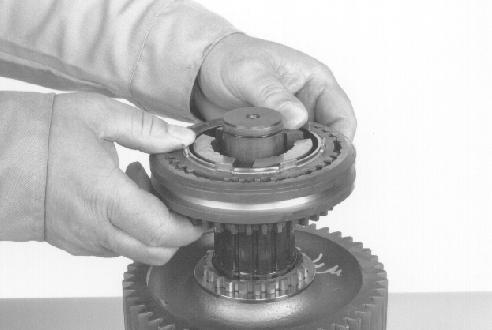
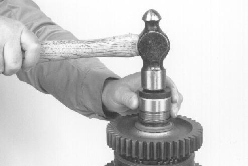
BP95F193 Use an acceptable driver or press to force the bearing onto the secondary shaft until the bearing makes contact with the thrust washer.
NOTE: If the bearing is not very tight on the secondary shaft, parts could fall from the secondary shaft when you install the secondary shaft in the rear housing. To prevent this, you can install a hose clamp on the output end of the secondary shaft. This will keep the bearing in position during installation of the secondary shaft.