3 minute read
Disassembly of the Oil Pump

from Case L-Series Loader Backhoe Transmission Update Kits Installation Instructions Manual 7-54022 - PDF

NOTE: If the transmission already has an “A4” pump, (refer to STEP 43 regarding proper identification of the pump) disassemble to determine its condition. Reassemble or replace as appropriate.
NOTE: If the pump is not identifiable as part no. 181199A4 as described in STEP 43, replace it with a new pump from NAPO. It will not be necessary (and is not recommended) to disassemble a new pump; however, before proceeding with the transmision rebuild, it is advisable to disassemble the original (used) pump even if it is not going to be re-used. Check for scoring of the housing and support by the gears. Check for excessive wear on the gear teeth. Check for looseness and excessive wear of the small gear bearing and supporting shaft. If any of the conditions are extreme, the charge pump was in the process of failing and has contaminated the transmission system with metal particles. If this has happened, also replace the torque converter and oil cooler. These must be ordered separately from NAPO.
STEP 311 STEP 312
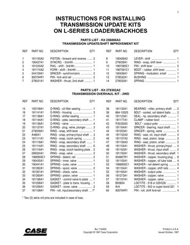
BP95F252 Remove the two Allen head screws which fasten the pump support to the pump housing.
STEP 313

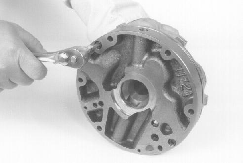
BP95F251 Remove the O-ring carefully. This part is NOT included in the overhaul or update kits. If necessary, replace with a new Oring from NAPO. BP95F253 Separate the pump support from the pump housing.
STEP 314
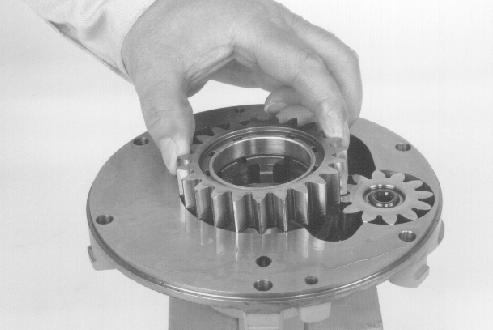
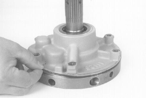
Remove the large gear from the pump housing. BP95F254

Remove the small gear from the pump housing.

STEP 316
BP95F255 BP95F261 Check the shaft for the small gear for looseness and deep wear marks from the needle bearing.
STEP 321
Check the bushing in the end of the pump support for wear, damage, and heat discoloration.
STEP 322

BP95F256 Examine the seal in the pump housing for wear, cracks, and damage. Replace with a new seal (from NAPO) if necessary. Remove the seal from the pump housing as shown if replacement is necessary.

STEP 317
Turn the pump housing over and examine the bushing for wear, damage, and heat discoloration.
STEP 318
Examine the bushing in the large gear for wear, damage, and heat discoloration.
STEP 319
Examine the needle bearing in the small gear for damage, missing or broken needles, and pitting. BP95F267 Remove the roll pin for the torque converter relief valve.

STEP 323
BP95F268 Remove the plug, the spring, and the ball for the torque converter relief valve.

BP95F269 Remove the roll pin for the oil pump relief valve. Be very careful because the large amount of spring tension will force the parts out when the roll pin is removed. BP95F599 Remove the plug, the spring, the pin, and the plunger for the oil pump relief valve.

17 16
10
11
4 15 14 18
8
7 19
9
6 2 2 12 13
14
15 16
BT95G180
1 2 3 5
BT95G180
1.Seal 6.Large Gear 11.Allen Head Screw
16.Roll Pin 2.Bushing 7.Needle Bearing 12.Torque Converter Relief Valve 17.Oil Pump Relief Valve 3.Pump Housing 8.Small Gear 13.Ball 18.Pin 4.Cap Screw 9.Shaft 14.Spring 19.Plunger 5.O-Ring 10.Pump Support 15.Plug