Tunnelling in the Follo Line project
Publication no. 29

Publication no. 29
NORWEGIAN TUNNELLING SOCIETY 2021
© Norsk forening for fjellsprengningsteknikk
ISBN 978-82-92641-50-7
Front page image: Bane NOR Nicolas Tourrenc
Layout: Konsis Grafisk AS konsis@konsis.no www.konsis.no
Its content reflects the state of knowledge at the time of completion. Whilst every effort has been made to assure the quality of the publication, it may nevertheless contain errors and omissions. NFF and/or the authors are not liable for any errors and/or omissions in the publication or for the consequences thereof.
Visit our website for a look into the future
Digitizing the rock mass world with a sound basis in serving the industry with research and advanced rock engineering.
- Automated joint mapping

- BIM modelling tunnel projects
- Dynamic parametric geo-design
- Machine learning for intelligent decisions
The Norwegian Tunnelling Society (NFF) is open to individuals, companies, institutions, and government services engaged in or associated with the construction industry where use of the underground and related work tasks and disciplines are central.
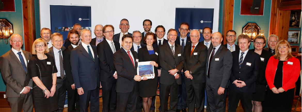
NFF has the tradition to present an English publication every year. In these publications we focus on different topics we think are relevant to share with our international friends and colleagues around the world. The publications are mostly written as a shared effort across the Norwegian tunnelling industry. This is not the case in 2021.
The Follo Line Project is by far the largest investment made in Norwegian onshore infrastructure as of now. The project consists of two parallel 20 km long urban railway tunnels among other constructions. Being such a special project in most regards, NFF decided that the 2021 publication should be dedicated exclusively to The Follo Line Project.
The publication is written as a joint effort among the client, contractors and consultants involved in the project. As such, the publication does not necessarily represent NFF’s position within the various academic topics. We do, however, believe it is of great benefit of the industry to share the experiences from this unique project.
We would like to express our gratitude to the project owner, contractors, consultants and suppliers to the Follo Line project. We greatly appriciate the willingness to share your experience through this written material.
The authors are credited at the start of each chapter.
Norwegian Tunnelling Society (NFF)
The International Committee

The Follo Line is a new 22 km long double track railway line under construction between Oslo Central station and the city of Ski (Kalager,2016). The Follo Line is built without stations between Oslo Central station and Ski. When the new line is in operation, it will work in interaction with the existing double track Østfold Line, which has 12 local stations between these two cities. The traffic will be divided between the two lines, depending on whether the trains will stop or not.
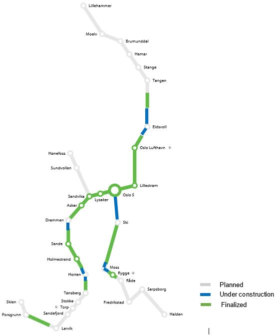
The Follo Line will be a part of the development of the InterCity railway line down to the border of Sweden (the Østfold Line) and is a priority project of the current National Transport Plan (NTP, 2014–2023). The status of the development of the InterCity railway network is shown in figure 1-1 below. The section between Oslo and Ski forms the core part of the line southwards towards Halden to the border of Sweden.
1-1:
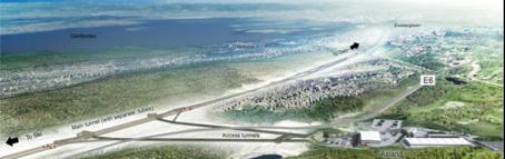
The project is divided in different sub-projects, as shown in figure 1-2 below. The main part of the project consists of a 20 km long tunnel, which will be the longest railway tunnel in the Nordic countries to date.
The Ministry of Transport and Communications (Samferdselsdepartementet) is responsible for transport of people and goods, telecommunication
and postal services and is the “owner” of the Follo Line project. The Norwegian Railway Directorate (Jernbanedirektoratet) is the government’s representative for railway services.
Bane NOR is a state company established to plan, build and operate the railway network. Bane NOR is reporting to a board of directors and to the Norwegian Railway Directorate.
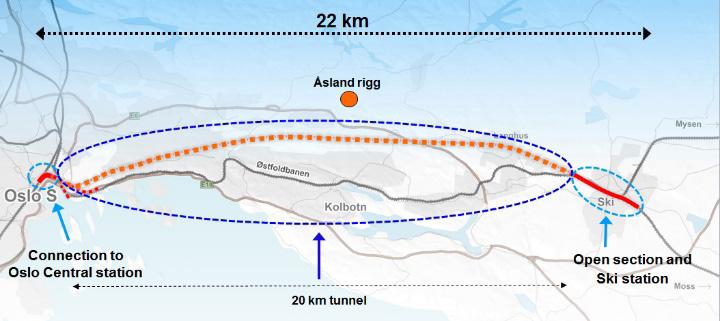
Figure 1-2: The Follo Line (orange) between Oslo Central station and the City of Ski with the 20 km long tunnel.
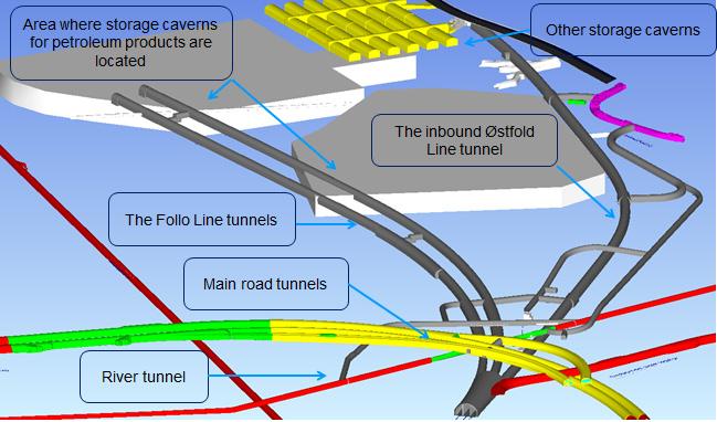
At the northern end of the tunnel, the Follo Line will be connected to Oslo Central station. A separate contract for the performance of the civil work for connecting the Follo Line to Oslo Central station and a relocation of the existing double-track Østfold Line outside the rock-tunnel section was awarded to the Italian contractor, Condotte in December 2015. At the tunnel portal are the new and existing railway lines going into an approx. 600m long cut-andcover section. To increase the efficiency, the inbound Østfold Line is diverting from the cut-and-cover section of the Follo line tunnels into an approx. 1.5 km long rock tunnel joining the existing line right after the tunnel portal, while the outbound leaves the cut-and-cover section after a short stretch.
After the cut-and-cover section the Follo Line tunnels run in two separate drill-and-blast tunnels until they meet the tunnel section excavated by TBMs. The civil part of the entire northern sections has been divided in various civil contracts. It was one contract for the railway system in the cut-and-cover tunnels as well as in the rock tunnel for the inbound
Østfold line, while the railway system for the major part of the drill-and-blast tunnels was added to the scope of work for the TBM section.
The contract for excavating the remaining 18.5 km of the tunnel with TBMs, including installation of the railway systems for the entire 20 km long tunnel, was awarded to the Joint Venture of the Spanish/ Italian contractors Acciona and Ghella, AGJV, in March 2015.
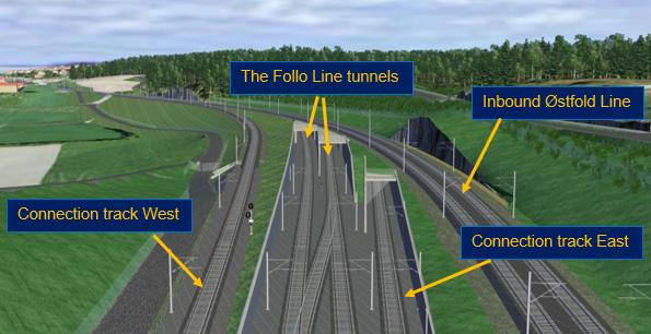
South of the 20 km long tunnel, named The Blix tunnel, the scope of work included both civil work and installation of the railway systems for a new 1.5 km long open section for the Follo Line including a total re-building and extension of the railway station at Ski, and a re-location of the existing Østfold Line in order to prepare for a future efficient utilization of the two lines. Between the portal of the Blix tunnel and the station, two connection-tracks are built to achieve conflict free connections between the two lines. This is shown in figure 1-3 below.
Figure 1-3: The tracks south of the 20 km long tunnel.
Connection track West will be used for southbound trains that have to switch from the Østfold Line to the Follo Line, and Connection track East will be used for northbound trains that have to switch from the Follo Line to the Østfold Line. A 600 m long tunnel, crossing right over the Blix tunnel, are built for the Connection track East.
The contract for performing the construction work for this section south of the tunnel, including the rebuilding of the station at Ski, was awarded to the Spanish contractor Obrascón Huarte Lain, OHL, in August 2015.
The contract strategy will be described in more detail in Chapter 4, “Contract Strategy”.
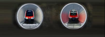
The 20 km long tunnel is, as the first railway project in Norway, built with two separate single-track tubes and in this way comply with inter-European safety requirements for long tunnels with cross passages every 500 meters. Se figure 1-4 below.
The cross passages will be used both for installation of the railway system equipment and as escape routes.
1-4
Two access tunnels were built in a pre-work contract to guarantee sufficient logistic capacity for the supply of four TBMs. Right in the middle of the project were for the assembly and logistic supply of the TBMs approx. 500m long tunnels with bigger cross section excavated, which will act as a rescue area for the Follo Line during the operation phase. A more detailed description of this will follow in Chapter 19, “Safety concept for the operation phase”.
When the Follo Line project will go in operation at the end of 2022, it will fulfill safety and maintenance requirements for a densely trafficked high-speed railway line, in addition to strict regularity requirements to ensure reliable traffic handling.
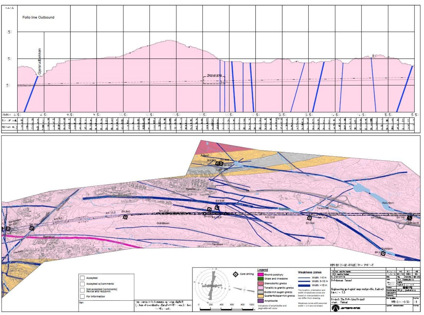
The rock mass within this project area consists predominantly of Precambrian gneisses with banding and lenses of amphibolite and pegmatite. In addition, some generations of intrusions occur. Sedimentary shale occurs in the northern part of the tunnel, close to Oslo Central station. Se figure 1-5 below.
Generally, the rock mass is quite homogenous and competent, with moderate jointing. Laboratory tests show that the rock is abrasive and strong, with uniaxial compressive strength varying between 100 and 300 MPa.
The Precambrian gneisses are folded in sharp isoclinal folds and they expose a clear foliation. Fracture zones in the gneisses have during several glacial periods been more exposed to erosion than the areas with solid rock. The rock surface has therefore been formed as deep valleys in the areas with major fracture zones, and peaks in areas with no or minor fractures. After the last glacier period, 10,000 years ago, these valleys were filled with marine sediments, mostly silt and clay.
Some of these fracture zones intersect the tunnel alignment, and leakages were expected in these areas during the excavation of the tunnel. In many cases, these zones were connected to each other as a network. Intersecting one fracture zone could therefore influence a large area. This is also illustrated in figure 1-6 below. This is described in more
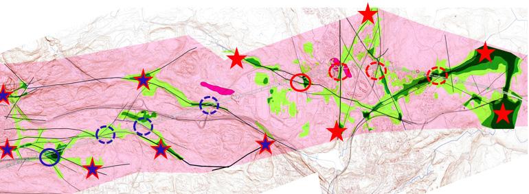
Figure 1-5: Geological longitudinal profile, which shows some of the intrusions (deep purple and yellow), shale in the north (green) and fracture-zones with a thickness of > 1 meter (blue)
Figure 1-6: The circles represent crossing-points between the tunnels and fractures. The fractures are connected to each other in different networks. The stars illustrate the areas affected by leakages from the crossing of the fractures.
details in Chapter 3, “Pre-construction planning and geological investigation”, Chapter 14, “Geological mapping and following up during the TBM excavation” and in Chapter 15, “Groundwater control and monitoring”.
To avoid settlements and damages on buildings and infrastructure along the tunnel section, the requirements for leakage into the tunnel, both during the excavation and after completion, were very strict. To fulfill the requirements, different mitigations to prevent leakages and development of settlements were an important part of the performance of the tunnel.
The overburden of the tunnel varies between 5 and 170 meters, and the groundwater table is normally located approximately 1 - 2 meters below the surface.
How the contractor prepared for handling of the geological conditions during the performance of the tunnel-excavation and the mitigations to avoid any kind of damages on the surface are described in detail in Chapter 14, “Geological mapping and following up during the TBM excavation”.
In Chapter 15, “Groundwater control and monitoring”, follows a description of how the impact on the water balance and on conditions on the surface were followed up during the excavation phase.

The main focus of this publication is the technical execution of the Follo Line project, including safety
and quality of the performance. The skills and experiences of all the involved parties are therefore an important key to success, but in this respect, there are also other topics which could be mentioned; When the contract was signed in March 2015, the client and the contractor decided to give priority to establish a good relationship for a common performance of this huge and multidisciplined project. Cultural differences were one of the topics that was highlighted. The client is Norwegian, and the contractor is a joint venture between a Spanish and Italian contractor, with subcontractors from even other countries. Workers came from all over the world to contribute to this project, so many nations and many different cultures have been represented on site. In the beginning, the client and the contractor spent time together including special cultural workshops to learn more about each other’s cultures, the way each party think, act and react, which was very valuable.
During the project execution various social events like skiing activities, common celebration of St. Barbara and celebration of achieved milestones were conducted.
The result is that even after 6½ year, the parties still have a good relationship within all levels of the two organizations. Even though there have been, and still are, disagreements between the parties, they have all the time been able to discuss and cooperate in order to find solutions.
The 20 km long tunnel for the Blix tunnel is divided in a northern section, which also includes a 1.5 km long tunnel for the inbound Østfold Line, and in a southern part, which represent 18.5 km of the tunnel. Different excavation methods were considered for these two parts of the 20 km long Blixtunnel.
In addition, a 600 meters long single track tunnel has been excavated for connection track East in the area around the southern portal of the Blix tunnel. In the same area, the two Follo Line tubes are also crossing over a tunnel, which was excavated for the crossing of a local creek, the Roås creek tunnel.
The Norwegian drill and blast method are known worldwide as an efficient method for tunneling within hardrock conditions, and the majority of the railway tunnels in Norway have, so far, been excavated using this method. Shortly after 2000, the use of tunnel boring machines (TBM) has been debated as a possible alternative to traditional drill and blast methods for a few railway projects. (Kalager, 2017)
In the northern part of the tunnel section, both the Follo Line and the relocated Østfold Line are located close to other existing tunnels, caverns, and sensitive installations. The excavation of both the two Follo Line tunnels and the inbound Østfold Line had to be performed with great care, as they crossed with a short distance under some of the main road tunnels close to the city of Oslo. A river tunnel located between these road tunnels and the new railway tunnels was required to be reinforced before the excavation of the railway tunnels were allowed to start-up in this area.
South of the area where the existing road tunnels and the new railway tunnels will cross, the relocated Østfold Line and the two Follo Line tunnels passed close to caverns and installations for storage and distribution of petroleum products. The complexity of these tunnel systems is shown in figure 2-1 below.
Careful considerations were required in relation to the selection of excavation methods to cater for crossings under the existing tunnels and strict requirements regulated the limits of vibrations when passing in the vicinity of storage caverns for petroleum products.
After consideration of the different possible excavation methods, and due to limited space for the start-up of a TBM in this area, it was decided to
excavate the tunnel for the inbound Østfold Line by a combination of drill and blast and drill and split methodology.
Applying the drill and split methodology, a grid of holes, 450 to 500 within a 70 m2 cross section, were bored into the tunnel face, after which the rock was split by hydraulic wedges. See an illustration of the drill and split methodology in figure 2-2.
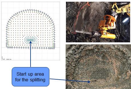
Whilst the drill and split methodology provides a careful excavation of the rock, it was a very slow process, providing approximately ½ meter excavated tunnel per day.
When considering the Follo Line tunnels, it was concluded that, due to limited space and restrictions related to ongoing construction works north of the tunnel portal, close to Oslo Central station, launching tunnel boring machines from the northern end of the tunnel was not feasible.
Consideration on use of the TBMs approaching from the south, revealed major risk exposures associated
with the schedule. Such excavation would need to occur as the last part of a total excavation of approximately 10 km and was identified as being on the critical path for the entire Follo Line project. Consequently, it was decided to use the same excavation method for the northern 1.5 km of the two Follo Line tunnels as for the inbound Østfold Line tunnel, careful drill-and-blast excavation in combination with drill and split. To avoid any conflicts with the schedule, it was decided to start the excavation of these three tunnels early, as a separate contract. In February 2015, this contract was awarded to the Italian contractor Condotte.
For the rest of the Follo Line tunnel section, extensive work was performed in analyzing and comparing different methods of excavation to determine the solution that satisfied the various requirements including an early completion. It was expected to perform the tunnel excavation within a period of approximately 3½ - 4 years from the first start-up until the tunnels were ready for the installation of railway system equipment.
To fulfill these requirements, excavation by drill and blast would have required excavation of seven access tunnels from different locations along the tunnel section. Some of these access tunnels would have been long and located within densely populated areas with potentially significant environmental impact.
For excavation by TBMs, it was identified a need for four machines to fulfill the schedule requirements.
Two different concepts for this excavation method were considered:
1. To excavate approximately 9 km northwards, towards a centrally located access point called Åsland, by two machines operating from the area around the southern portal in combination with two machines operating from the centrally located point at Åsland, boring further 9 km in the northward direction.
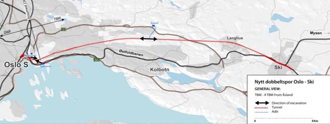
2. To operate four TBMs from one centrally located access point at Åsland. Two machines excavating in the northward direction towards Oslo, and two machines excavating in the southward direction towards Ski.
The principles for the operation of the two different excavation methods are illustrated in figure 2-3 and figure 2-4 below.
Figure 2-3: Excavation of the 18,5 km x 2 long tunnel by drill-and-blast required performance from seven access tunnels distributed along the tunnel in addition to the access tunnel required for excavation of the northern 1.5 km long tunnel.
Figure 2-4: Excavation of the 18,5 km x 2 long tunnel by four TBMs operating from one centrally located rig area.
As a result of all the analysis, it was identified that, in theory, the two excavation methods were quite identical regarding estimated progress and cost, but due to environmental impact, using TBMs would be beneficial for the project.
Based on these results, it was decided that the remaining 18.5 km of the tunnel section should be excavated by four TBMs operating from one large and centrally located rig area, at Åsland, with direct access to the main road and with a limited number of neighbors in proximity to the rig area. The rig area was large enough for all the activities related to the tunnel production to take place “in-house” within this area. This also included a large area for deposit and re-use of the excavated material. An EPC contract for performing the tunnel excavation of these 18.5 km x 2 by four TBMs, including the installation of the railway systems in the entire 20 km long tunnel, was awarded to the Spanish/ Italian joint venture Acciona and Ghella, AGJV, in March 2015.
Due to strict requirements regarding leakages into the tunnel, it was decided to use double shell TBMs and install a watertight single shell lining, as a part of the TBM tunnel production. In some densely populated areas, where leakage into the tunnel were expected during the excavation, pregrouting from the machines were mandatory. In other areas, the need for doing pregrouting ahead of the machines were, on a daily basis, decided, based on results from probe drilling, different geological mapping and measurements compared to relevant leakage criteria for the specific area. The machines were equipped to perform pre-grouting. Se Chapter 10, “Tailormade TBMs for boring in hard rock at the Follo Line project”. The performance of pre-grouting during the excavation is described in more details in Chapter 14, “Geological mapping and following up during the TBM excavation” and in Chapter 15, “Groundwater control and monitoring”.
The machines were assembled in two large caverns, a northern and a southern cavern. Two machines excavated in the northern direction towards Oslo and two machines excavated in the southward direction towards Ski. This is described in more details in Chapter 10, A number of other access and logistic tunnels were excavated for the TBM tunnel production as well. This is shown in figure 2-5.
The production of the concrete lining took place within the rig area. 141 000 segments, or 20 000 rings of segments were efficiently produced from three factory units. In addition to this, 20 000 invert segments were also casted in the factories.
Approximately 10-15% of the excavated material was planned to be crushed and re-used as aggregates for the production of concrete. The result of the analyses required to achieve acceptance for this re-use are described in more details in Chapter 9, “Use of the tunnel spoil”.
Most of the excavated material were filled up in the northern part of the rig area, in accordance with strict requirements to achieve a quality filling. The filling will act as a basement for development of a future residential area. This re-use of the short travelled excavated material created a win – win for the project, the municipality of Oslo, who will be responsible for the future development of the new residential area, and for the environment. This is also described in more details in chapter 9.
By using conveyor belts for the transportation of the excavated material all the way from the machines to the deposit area, contributed to a reduction of 27,000 tons of CO2, compared to the alternative where the tunnels should have been excavated by drill and blast from seven different access tunnels. For the drill and blast alternative, the excavated material would have been transported by trucks all the way from the different tunnel faces to the deposit areas.
All the workshops and the water treatment plant had a central location close to the portals of the two access tunnels, which contributed to an efficient production at site.
Most of the workers were accommodated within the rig area, which also created less traffic on the road. Both the contractor and the client have their offices within the rig area, which have enabled for efficient and good cooperation between the parties during the entire construction period.
All these “in-house” activities and solutions for logistics and re-use of the excavated material, reduced the traffic in and out of the rig area. One rig area location, with a limited number of neighbors, instead of seven rig areas and access tunnels located
within densely populated areas, gave a huge benefit regarding the environment and the impact related to thousands of neighbors along the tunnel section. Figure 2-6 shows an illustration of this compact and efficient rig area.
Parameters which need to be taken into consideration when excavation method is being assessed, are the location and length of the tunnel, the location and size of suitable rig areas and length of eventual access tunnels, requirements regarding leakage criteria and expected impact on the environment. In addition, impact on the schedule and cost are always relevant parameters.
To make sure that the correct tunnel excavation methodology is selected, which properly considers the above mentioned parameters, it is important to conduct the assessment as an early activity of tunnel projects.
There are certain schools of thought, which question
whether the decision of excavation method should be taken by the client or the contractor.
Under normal circumstances, this decision should always be taken by the client. There are many reasons for this, including overall responsibility for safety and the environment in addition to ensuring that the contractors are allowed to focus their fully attention during the tendering phase in providing comparable and compliant bids reflecting a common and fully considered excavation methodology. Different excavation methods may also influence on required area development plans and contract strategy for the performance of the projects.
The choice of the right excavation method is an important key for the success of the project.
The first geological investigations for the Follo Line railway project were performed during the early 1990’s as part of a master plan for Oslo-Ski. In 2007 the Follo Line project started to plan and conduct more geological investigations, evaluating possible
tunnel alignments and tunnel concepts. In 2009 it was decided a direct alignment for the Follo Line, with no stations between Oslo and Ski. A two tube single track solution were chosen in 2010, resulting in a total of 40 kms of tunnel.
Figure 3-1: Overview of the project area.
More comprehensive investigations were done over a number of years, until the construction of adit
tunnels started at Åsland in 2014.
Figure 3-2: Adit tunnel system at Åsland.
The geological investigations can be divided in three main topics.
1. Rock mass mapping and characterization, focus on fracture zones and jointing
2. Soil layer parameters and thickness of sediments above the rock-surface
3. Hydrogeology.
The aim of the investigations was to avoid or minimize tunneling in difficult ground-conditions, to reduce the risk for damage to buildings or infrastructure and valuable nature, and finally, reduce
the risk for cost escalation of the construction work. However, since the Follo Line railway tunnel is built as a high speed line, adjustments of the alignment due to the geology was limited.
Investigations of the ground conditions covered desk studies of maps and existing reports, inspections of tunnels in the vicinity of the project, geological and engineering geological field mapping, seismic refraction profiling, core and well drilling, resistivity profiling and rock stress measurements. All data reports from geological investigations are compiled in one large report, ref (1).
NGU (the Geological Survey of Norway) conducted an upgrade of the geological background material in 2007. In addition, they also performed detailed structural field mapping in 2007 and 2011, ref. (2) and (3). The Engineering companies Aas-Jakobsen and Multiconsult (FPS) performed engineering geological field mapping, assembling of rock and soil information from existing reports and inspections of tunnels/caverns in the project area, ref. (4). In 2009 NB&A ref. (5) performed rock mass characterization of rock exposures for input to the QTBM prognosis model.
Seismic surveys had been conducted by Sverre Myklebust A/S in 1993 and by GeoPhysix AS in the period 2008 to 2012. A total of around 7,5 km of seismic profiling was done in the period 2008-2012. The seismic profiling gave information of layering, seismic-velocity, and fracture zones.
NGU conducted resistivity profiling along 19 profiles with a total length of 12 400 m.
In this study, both soil cover and fracture zones in bedrock were of interest. Due to this, the data were processed focusing both on horizontal and vertical structures. To get control of technical installations and possible sulphides in bedrock, induced polarization (IP) was measured. An advantage of resistivity profiling is the possibility to provide information about dip and width of fracture zones.
Information of deposits/soil layers over the tunnel were investigated by soundings for confirmation of bedrock level and for detection of type of soil. Test series of soft deposits/ sediments from areas of special interest were sent for laboratory analysis. Main objective was confirmation of bedrock, and to investigate settlement potential in the soil. About 420 soundings were conducted for the Follo Line project and about 700 soundings from other projects were collected.
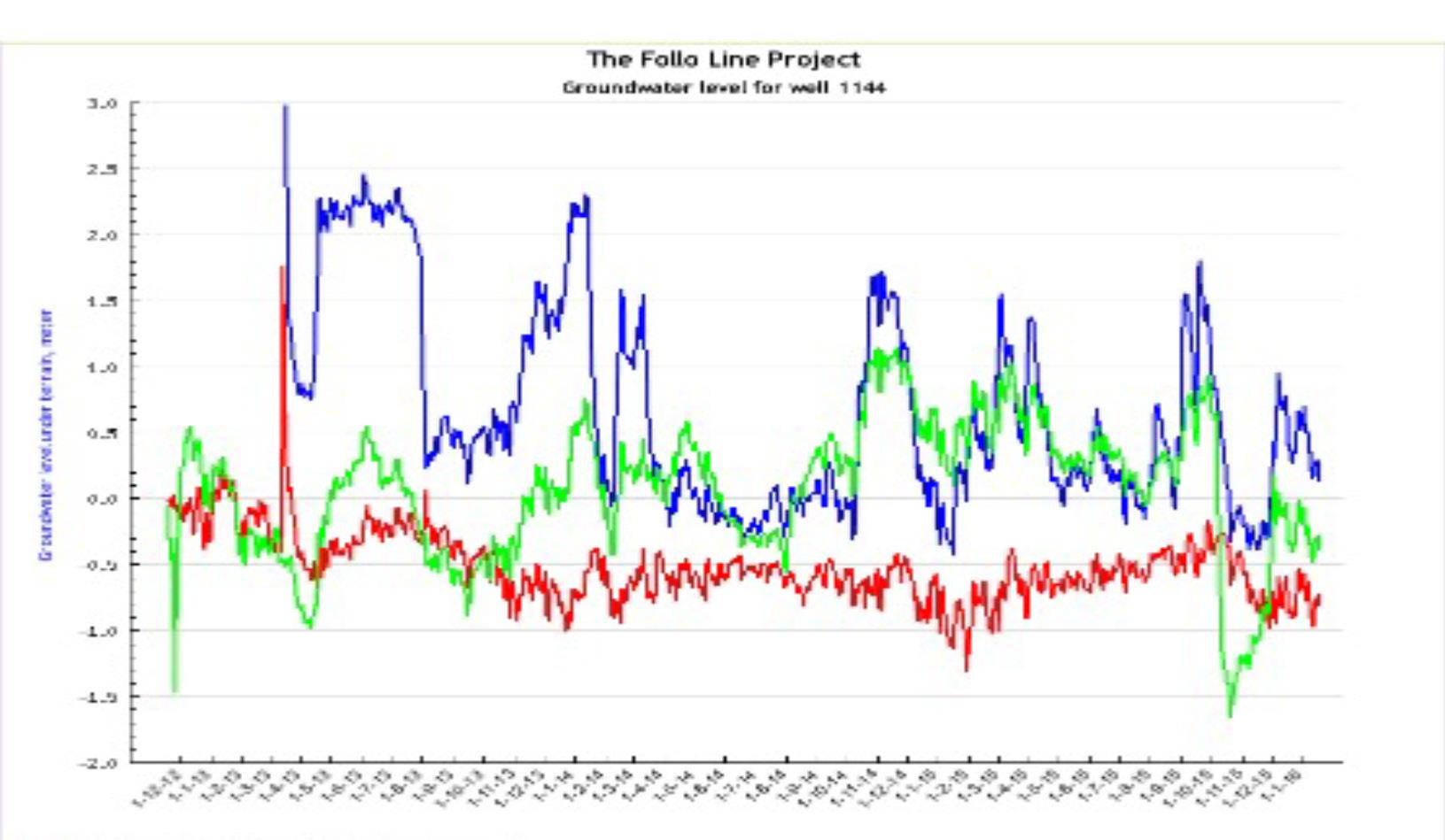
About 130 piezometers in soil for pore pressure measurements was installed for monitoring of pore pressure along the tunnel section. It was considered important to start monitoring some years before the construction work started, in order to document natural seasonal variations in pore pressure. This is described in more details in chapter 15.
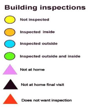
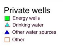
To get information regarding foundation and condition of buildings prior to construction, an extensive
program for inspection of buildings and location of wells along the tunnel alignment were performed. This is described in more details in Chapter 15.
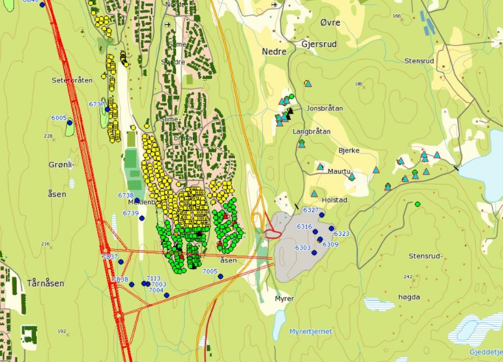
Figure 3-4: Building inspections and located wells at Åsland area.
During the pre-investigation phase, 18 inclined holes was drilled in the project area with a total length of about 2000 m. About 500 Lugeon tests were performed, and 32 core samples were tested by SINTEF Byggforsk for rock mechanical properties.
The main purpose of the core drilling was to determine width and character of selected fracture zones, as well as leakage conditions. After the selection of TBM as the excavation method for the main part of the tunnel section, some additional core drillings were performed in solid rock, far from known fracture zones, in order to have undisturbed tests samples.
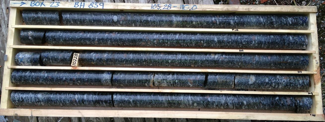
Figure 3-5: Examples of rock cores from BH 839, 105, 28-110m. Amphibolitic gneiss with garnets.
All core drilled boreholes were logged for rock type, and properties as RQD, joint infill, joint roughness, and degree of weathering, ref (6). All cores were photographed, see figure 3-5.
In connection with this project, a total of 9 rock wells were drilled in an early phase. Four of the wells are located on the plateau from Ekeberg to Nordstrand (chainage km 3.4 to 7.0) and the last borehole was located on Grønliåsen (at chainage km 11.0).
The main aim with these boreholes were to get an indication of the groundwater level / pore pressure in the hard rock aquifer, and to verify if a hanging groundwater exists at the upper part of the rock formation. Hence, all the wells have been divided in two sections, one measuring the groundwater level in the upper part of the bedrock formation and another in the lower part of the well. This is described in more detail in chapter 15.
Lugeon / water loss measurements were performed in all holes.
Rock stress measurements was conducted by SINTEF at three locations, one at Ekeberghallen in the north and two from the adit tunnels at Åsland close to midpoint of the tunnel stretch. The stress measurements show stress vectors significantly higher than theoretical estimations based on the overburden in the area.
Laboratory investigation of rock samples have been carried out both on core samples and on blocks of rock.
The following testing methods have been used:
• DRI = Drilling Rate Index
• CLI = Cutter Life Index
• UCS = Unconfined Compressive Strength
• PLT = Point Load Test
• CAI = Cerchar Abrasion Index
• Quartz content
• Brazilian Tensile Strength
• Modulus of Elasticity and Poisson’s ratio,
In addition, two tests of gouge material were conducted.
Being an EPC contract, the contractor, AGJV, performed additional pre-investigations in 2015-2016 as part of the detail design process. Additional investigations that were performed:
• 8 core drillings
• 9 probe drillings
• 17 piezometers
• 8 resistivity profiles
• 11 seismic profiles
The bedrock within the project area consists mainly of Precambrian gneisses and amphibolite. Younger dykes, originating from the Perm period, also occurs. On a short stretch in the northern part of the tunnel, also sedimentary rock, as black shale and limestone, occurs.
The Precambrian gneisses, which occur in the project area, are divided into 3 main groups. The geological map of the NGU-report (2) refers to the following lithologies:
• Tonalitic - to granitic gneiss
• Quartz-feldspathic gneiss
• Biotitic augen gneiss
Detailed registrations in tunnels, caverns and at the surface showed that the different lithological units at a smaller scale have a rather heterogeneous character. In addition to the main groups of rocks, several generations of intrusions occur. Part of the older intrusions still have the character of diabase, while others are transformed into amphibolite and folded into the gneisses. These amphibolite dykes and sills make up a larger portion than the Permian intrusives. The youngest Permian intrusives are both dykes and sills following weak layers in the foliation and along fracture zones. One special intrusion is a 20-30 m thick rhomb porphyry dyke that can be followed from Ekeberg southward over a distance of approximately 15 kms.
In addition, observations from field mapping and core drilled holes showed that amphibolite lenses and intrusives parallel to the foliation occur. About 15 % of the rock lithology in the cores is amphibolite.
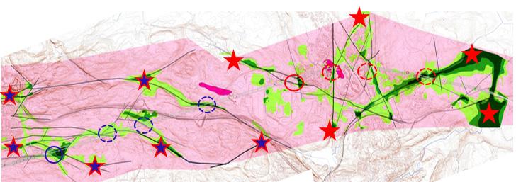
The project area is intersected by several fracture zones, also defined as “weakness zones”, as shown
on the engineering geological maps, se example in Figure 3-8
Fracture zones occurred as jointed zones with densely jointed areas, or as crushed zones where the rock material was crushed and showed clay transformation of material, partly also with clay gouges that can range from a few centimetres to several decimetres thick, ref (4).
The zones marked on the geological maps are divided into three categories: Width 1-5 m, 5-10 m and more than 10 m. Fracture zones illustrated on the drawings by one line is normally not one single zone, but often crushed or jointed sections divided by more competent rock sections.
Core drillings were carried out to map the course and characteristics of prominent fracture zones. The most pronounced fracture zones, that were intersected by core drillings, showed crushed sections up to approx. 20 m length in the borehole.
The fracture zones were connected to each other. The impact of this was that leakage from one zone, when intersected by the tunnel, could result in reduction of the pore pressure within a large influence area. This is also described in Chapter 15.
Also, the seismic refraction surveys provided information about fracture zones in the rock mass. These registrations described the zone’s course along the surface, but nothing about dip and character towards depth. Most often the seismic measurements showed some overexposure of zones in the surface. Resistivity profiling gave an indication about dip angle for the zones, and interpretations form these profiles were included when preparing the geological profiles.
Zones occurred in two main directions, N-S and E-W. There are deviations from these directions
with some zones oriented in direction NW-SE and NE-SW.
Fracture zones along the N-S direction was of special concern since this is almost parallel with the alignment for long parts of the tunnel.
During field mapping, registration of joint character, strike/dip and joint spacing were registered. These observations were grouped for sections of the project area and presented as rosette plots. A rosette plot has been prepared for each of the geological maps, see an example of this in figure 3-8.
Studies of joint registrations showed two main joint sets. One joint set was steeply dipping and had roughly an E-W oriented strike. The other joint set followed the foliation, which mainly was oriented N-S and dipping westwards (35°-90°).
Joint characteristics, roughness and undulation of joints were recorded where these parameters were possible to detect.
The average joint spacing for the various joint sets
observed at the surface did not seem to be influenced by the proximity to the fault zones. One reason for this may be that some rock exposures were small, making it difficult to determine the general joint spacing. Another reason might be that random joints were included in the average joint spacing, as these joints did not belong to any joint set. A third reason could be that areas most strongly influenced by the fault zones, usually form soil covered depressions in the terrain and therefore do not show rock exposures at the surface. During excavation, it could be expected to encounter zones more fractured and with closer jointing than what had been mapped at surface exposures.
Joint spacing recorded on rock cores from the core drillings (RQD and joints pr. m) indicated more fractured rock than registered at the surface. However, the results could be misinterpreted, as there is often difficult to decide whether a joint is caused by in situ fracturing or a mechanical break from the drilling operation.
From NB&A Q-tbm report, ref (5), typical range of RQD values are in the range of 75-100 %.
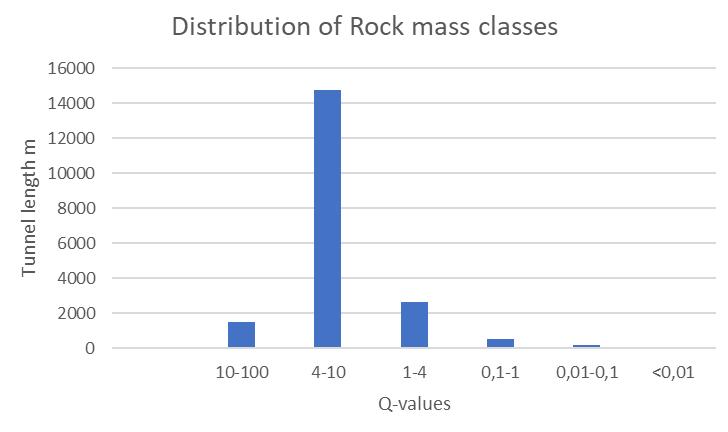
Q-parameter data was collected by Multiconsult for estimating rock support classes, ref (4) and by NB&A for input to the Q TBM prognosis model, ref (5)

Distribution of rock mass classes (Q) is shown in figure 3-9 below.
Figure 3-9: Distribution of rock mass classes.
NB&A conducted Q-parameter mapping along the project area, but along a slightly different alignment than the final alignment. The results were divided in
two main sections north and south. The collected parameters excluded cores and fracture zones.
Figure 3-10: Distribution of rock mass classes from the Q TBM field mapping.
About 32 core samples and 8 hand size rock samples were collected and tested for strength and bor-
ability properties. A total of around 70 tests were conducted. Table 3-2 below shows typical test results, ref (1).
Lithology MPa Is50 MPa % Kg/m3
Amphibolite 33,5 12,3 188,2 8,8 8,6 3,5 10,1 3136
Pegmatite 52,5 4,5 119,7 7,5 3,8 57,5 2644
Gneiss 38,4 6,6 145,5 8,6 12,1 4 31,4 2681
Table 3-2: Strength properties for different rock types.
The project area is located below the marine limit (maximum sea level after the last glaciations) which is 220 meter above present sea level in this part of Norway. During several glacial periods, areas with fracture-zones have been more exposed to erosion than areas without fractures and formed wallies and peaks of the rock-surface. Thick layers of marine silt and clay deposits can therefore be found in these wallies within the project area. Normally there is also a moraine layer towards the rock surface. In addition, some limited areas were covered by organic deposits (peat/bog). Both marine- and organic deposits are settlement-sensitive to pore pressure reductions, ref (4).
The project area has a limited groundwater extraction potential. Water leakages into the tunnel may occur when the tunnel crosses one of the fracture zones. If the leakage is not stopped, or reduced by pre-grouting during the excavation, the fracture zone, and eventually also the adjected zones, may act as drainage channels, which will reduce the pore pressure in the silt or clay sediments above or within the influence area of the tunnel. This is described in more detail in Chapter 14, “Geological mapping and following up during the TBM excavation” and in Chapter 15, “Groundwater control and monitoring” It is also illustrated in figure 3-11 below where all the lines, added on the ordinary map, represent a network of fracture zones with a thickness of at least one metre. This fracture zones are also illustrated in figure 3-8 above.
Figure 3-11: When the tunnel crosses a fracture zone, the connected network of zones may act as drainage channels and result in reduction of pore-pressure within a large area.
A drop of the pore pressure will result in settlements and damages of buildings and infrastructure founded on these sediments. A number of piezometers (19) were installed during the pre-investigation phase to map the pore pressure at the rock surface below the clay deposits. This is described in more detail in chapter 15, “Groundwater control and monitoring”
The depth to the rock surface varies from approx. 2.5 m to more than 20 m within the project area.
The most vulnerable residential areas above the tunnel were located at the Nordstrand area at km 5 – 8 in the northern part of the tunnel section, and in the south at Ramstad terrace km 19.6 – 20.4.
The Follo Line is located east of the Oslo Fiord under catchment areas draining into Bunnefjorden (an arm of the Oslo Fiord). Average annual precipitation is in the range of 705 to 830 millimeter.
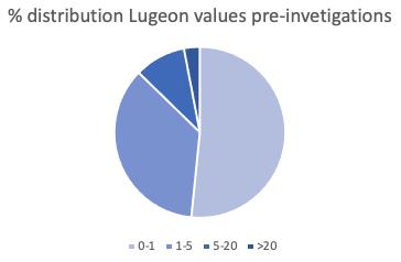
Hydraulic conductivity in the rock mass was calculated based on Lugeon tests. One Lugeon is defined as the water loss in liter/minute/m borehole with an excess pressure of 1 MPa. Ideally one (1) Lugeon corresponds to a hydraulic conductivity of 2,3 ∙10-7 m/s
During the pre-investigation phase, several investigation holes in rock were made, mainly core-drilling, but also some rock wells. Several in situ Lugeon tests were performed in these holes to get a better basis for evaluating rock permeability or potential for water leakages to the tunnel, ref (4). All data from the tests were put together in different categories.
• 0-1 L (almost tight)
• 1-5 L (small water loss)
• 5-20 (medium-high water loss)
• >20 (high water loss)
Figure 3a-13 shows data from the pre-investigations divided in these 4 categories in a sector diagram.
Quite a large share, 87 % is in the range 0-5 Lugeon (tight rock or small water loss).
Figure 3-13: Distribution of Lugeon values pre-investigations core holes and rock wells.
1. FPS . UFB-30-A-30063 Geotechnical and Geological Investigations Data Report. 2014.
2. NGU. Geologiske forhold langs planlagt jernbanetrasé Oslo - Ski. Rapport nr. 2007.048. 2007.
3. —. Resistivity measurements and structural geology along the railroad tunnel transect OsloSki. Report no. 2011.004. 2010.
4. FPS. UFB-30-A-30064_02B: Summary geological data report. 2014.
5. Assosiates, Nick Barton &. Driving prognosis for TBM by Nick Barton & Assosiates, based on surface mapping and the Q-method. 2009.
6. FPS. UFB-30-A-30062_03B Core drilling report. 2013.
NGI (2018) Report 20180498-01-R. Kontrolldata fra fylling av borkaks fra Follobanetunnelen. Evaluering av geoteknisk kontroll av fylling av borkaks.
Norwegian Standard NS-EN 12620+NA: «Aggregates for concrete»
Silje Gystad Ytterdal, Elisabeth Grasbakken, Berit G. Petersen. 29.05.2017. “Memo- Evaluation of risk regarding pyrrhotite in aggregates.” Bane NOR, Oslo, Norway.
Statkraft (1986). Prosjekt fullprofilmasser. Materialegenskaper. NGI report 85607-1. 30. may 1986.
Acciona & Ghella (AGJV) (2019)
UFB-31-A-67013 00E. Project: The Follo Line project, EPC TBM. Follobanen, Åsland. Spoil Area. Final Report.
Barnard and Heymann (2015) The effect of bedding errors on the accuracy of plate load tests.
J. S. Afr. Inst. Civ. Eng. vol.57 n.1 Midrand Jan./ Mar. 2015
Dahl, Marianne. (2018)
Investigation of geotechnical properties of TBMspoil from the Follo Line project. Master- degree thesis for Marianne Dahl. NTNU 2018.
NGI (2016)
Report UFB-30-A-70072. Application of TBM spoil as a quality fill for Gjersrud/ Stensrud township. Follobanen. Bane NOR.
The Follo Line project was not set up as a BIM project but had some comprehensive requirements for 3D-model delivers. The model was aimed to be an integrated part of the design and construction process. The purposes for the model are listed below:
• Display of information about existing facilities, terrain, geology and surface layers.
• Communication of proposed and selected design.
• Basis for interdisciplinary control/check.
• Verification of visibility from train to railway signals.
• Verification of solution for security, emergency response and evacuation
• Ensure coordination across disciplines and contracts
• Basis for deviation control/check
• As-built documentation
The history of using models at the Follo Line project starts many years before the start of construction phase. The main purpose of using models, in addition to the mentioned points on the previous page, is to have an overview of what is included in the project. From an early stage, the model has been actively used for such purpose, where all the mentioned bullet points in some extensions have been implemented in the work (with varying degree and detail).
The purpose of using models in the project was to use them to follow up construction phases of each sub-project, link the models with PIMS (completion management), perform collision controls, coordinate the interfaces of the different phases and to coordinate between the actors to compare the design of the different systems along the sub-projects. Later, after the completion of the construction steps, the models will be used for maintenance of the operation and maintenance division.
Models used in the tender documents was different to models that was supplied by the contractors. The original models consisted of discipline models for each subject area and 3 different assembled models (discipline model, coordination model and basic model). The degree of detail of the models varied since it was of different designs and railway engineering areas. The discipline model was certainly used most for clash control. Most of the 3D model is developed based on 2D drawings, but some tricky elements like the collar from the TBM tunnels into the CPs or the cableways from the manhole in front of the CPs into the various technical room inside the CPs were developed in 3D. The deliveries have further been divided into two different types of models: a discipline model and a coordination model. Table 4-1 below describes what is characteristic of the two different models.
The coordination model consists mainly of geometry giving a good visualization of what is to be constructed. Some objects also contain information like tag numbers.
The use of 3D has changed a lot during the project, since the contractor almost started from zero, but came quite far with the BIM development. The contractor, Acciona Ghella Joint Venture (AGJV), uses 3D a lot at the Follo Line project. Drawings are made from 3D models, tunnel profiles are scanned, and the actual construction are later compared with the model. Some objects, like rock bolts and lining segments, are implemented in the model after installation.
Table 4-2:
There has also been a special focus on visualization of ground investigations and data collected during excavation. These pre-excavation data have extensively updated the model during construction. As the tunnel is mainly being bored with double shield TBMs, the possibilities for traditional geological mapping were limited. This has resulted in an extended use of different technologies to collect as much geological- and machine related information as possible during construction. This is shown in table 4-2.
All these investigations create huge amounts of data. To put it in perspective, more than 36 km of OTV images have been produced, approximately 2000 face mappings have been performed and water measurements exists for more than 8000 probe drilling. Every data input includes some information about the geological conditions, but getting the complete overview is a challenging task. In addition to this, there has been an extensive program of pre-investigations prior to excavation, making the “geological database” even more comprehensive. Consequently, the site geologists started to look into methods for digitalizing the data and bringing as much as possible into the same model. Most of the data collected at underground projects will be georeferenced, either by real world coordinates or by positions along an alignment. This has been the basis for organizing data at the Follo Line project.
The purpose of performing face mapping is to gather general geological information and to get input to assess the fracture factor ks-tot. Mapping is normally performed once daily during the maintenance shift in the morning. Depending on the excavation rate there is 15-20 tunnel meter in average between each face mapping. Geological mapping of the face normally consists of the following parameters:
• Observations of rock types
• Presence of hard and abrasive minerals like quarts or garnet
• Signs of weathering
• No. of fracture set and fracture spacing, fracture plane roughness, infilling or aperture.
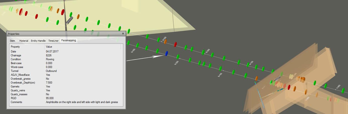
• If present, which fractures- or weakness planes contribute to fall-out or overbreak
• Water seepage from the face
• Photos
The fractures are often challenging to map correctly through a cutterhead inspection, due to narrow workspace and relatively poor light conditions. In addition to the limited view through the cutterhead, there are only two dimensions visible at the tunnel face, which in combination with a non-functioning compass (reacting with the TBMs metals) makes it difficult to map the fractures accurately [4].
With this in mind, the challenge was how to include the results from the mappings into a model. Solutions for digitalizing face mappings sheets, and software like TUgis was looked into. With the lack of accuracy in the face mappings, a detailed modelling seemed unnecessary. A simpler approach was therefore chosen. By modelling a disk along the alignment for each mapping and enriching it with attributes from the mapping, different parameters could be visual-
ized together with other investigations. Figure 4-2 shows face mappings where RQD values have been colored from high (green) to low (red). Fracture zones from the pre-investigations are modelled as brown planes. This gives very visual feedback of where zones are intersected, compared to the predictions.
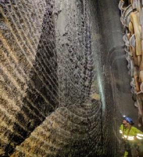
The Follo Line project have used a solution by 3GSM to create 3D imagery of the tunnel face. Photographing of the face in 3D is performed by
installing an autonomous imaging unit at one of the inspection openings during maintenance shift. When the cutter head is turned, a circular video is captured. Advanced software generates scaled and oriented 3D images from measurements taken (3GSM) [4]. The result is a permanent documentation of rock mass conditions. From the 3D images it is possible to identify and measure the overbreak and perform geological mapping. This is shown in figure 4-3. The generated surface is also exportable to dxf or as a point cloud making it easy to include in a geological model.
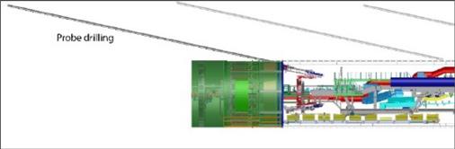
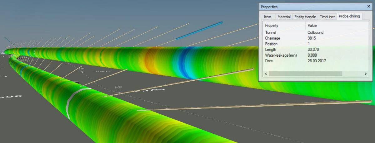
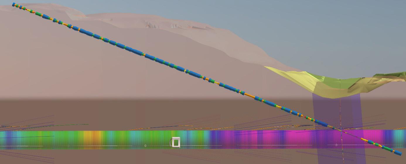
Probe drilling is performed to obtain information ahead of the TBM on geological conditions, especially weakness zones and water seepage. Probe drilling is, depending on the TBM progress, performed daily. There are 38 openings around the shield dedicated for probe and grout holes. The TBM’s are equipped with two percussion drill machines for probe and grout holes drilling. The probe holes are normally drilled to around 40 m length in rock. Figure 4-4 below shows the probe holes drilled ahead of the daily positions of the two TBMs.
MWD is collected during drilling making it possible to detect variations in rock hardness and to discover weakness zones [3]. Although MWD can be a useful tool, the lack of compatibility with other software has been an issue. As the data is only accessible in a separate software, it is easily forgotten and hard to compare to other data. For the geological model, probe drillings have therefore been visualized as cylinders in the location of drilling. Water leakage measurements in the boreholes have been modelled as cylinders, where the radius of the cylinder indicates leakage value.
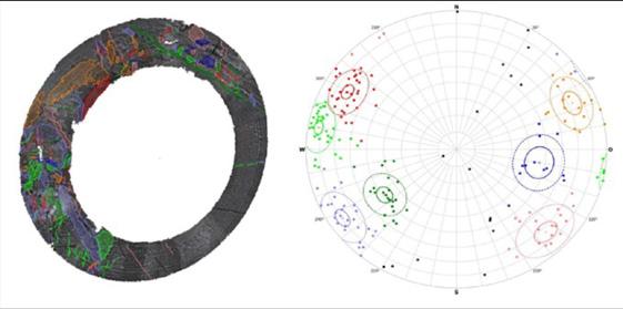
Televiewing has been done in one probe hole approximately every 20m, to create an overlapping series of images. The instrument for televiewing has compass to keep track of borehole orientation. To get a good picture the hole should be dry and therefore directed upwards. The televiewing picture has high resolution and gives good information of rock types/lithology along the hole.
Open fractures are usually easy to detect, whiles closed fractures or fractures with small aperture can be difficult to observe in the picture. Sometimes a line of brownish color from weathering can reveal the presence of a fracture that is otherwise undetectable in the picture. Also fractures in dark rock like amphibolite can be difficult to spot.
Fractures and weakness planes that are believed to contribute to the rock breaking process under TBM boring are marked on the picture with the software well cad. With the same software it is then possible to decide strike and dip of these structures. This is illustrated in figure 4-6 below.
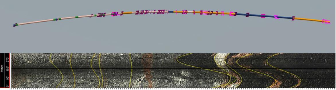
The logged OTVs have been modelled using output from well cad, as well as deviation measurements. This called for creating a custom script to read the files and generate the geometry. One the script was made, reading and importing huge amounts of data into the model became an easy task. The models are all built up by geometry and attribute data. By doing this the model also acts as a database, where fracture data or lithology statistics can be exported for selected sections of tunnel. As an example, this is a useful feature to create fracture pole plots for selected areas.
Core drilling is performed at the front of the TBM’s on regular basis to get rock material for laboratory testing (4 m core) and cores for geological logging (2 m cores). Although modelling of core drillings from the tunnel can be done the same way as core drillings in the pre-investigations, digitalization of the data has proven to be a huge job. As data from core drillings traditionally have been delivered as pdf reports, large amounts of manual labor is needed in the digitalization process, and therefore not a focus area of this project.
Core drillings from the pre-investigations have been modelled. Parameters like RQD, lithology, lugeon
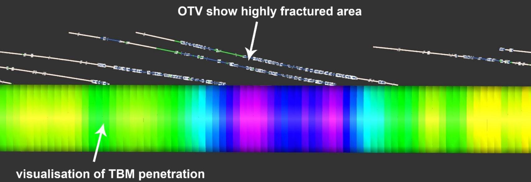
Figure 4-8: Model of core drilling, where cylinder radius and colour indicate value.
measurements and fracture infill have all been added to different layers. This makes it possible to customize the model depending on what data you
are interested inn. The example above shows how RQD values vary when entering into a fracture zone.
Figure 4-9: Model of core drilling, where cylinder radius and colour indicate value. Core drilling is here seen together with TBM progress model and probe drillings.
The Follo Line project has in certain areas of modelling achieved good results, however somewhat fragmented. The project design has been modelled to a high detail level, but there has not been a clear enough strategy in the contract documents on how to use this in production. Objects are built to drawings and there is a lack of input from construction to the model. As a result, the model becomes a tool for design, and not an active aid during construction as it could be. This being said, useful results have been achieved with production data as well. Large amounts of the collected geological data have been implemented in the model.
This can be attributed to the missing of an overall concept at the project start. The contracts contain a specification for 3D, which is at rather low level. Working in BIM as such was not required, only a general 3D model and an engineering database needed to be developed. Almost all the design is done in 2D and the 3D model is based on these drawings.
In order to improve this, future projects are in an early project phase recommended to establish [2]:
• A BIM manager
• A general BIM strategy
• A project information system
• The way of information exchange
• Unique ID codes (tags) for certain objects
• A strict policy for the use of these IDs in the various software tools (design, schedule/planning and cost calculation)
It is important that clients define clear requirements, which do not leave much room for interpretation in the contract documents.
The use of BIM in the Follo Line project (and other projects) can be further worked out. Some ideas of how to expand the use and what we would like to achieve is presented as examples below:
• Use the 3D model for evacuation simulation and training for train personnel and rescue forces like fire fighters etc.
• Use the 3D model for progress monitoring. On the marked some software packages can be found which do this. They are not really working well for infrastructure-projects, but they work good for buildings. On a simple approach, one can simply mark objects to be built with some colors for illustration.
1. Lawton, M., Hansen, J.N. (2019). Digitalization in Norwegian Tunneling. Case Study - The Follo Line project. Publication no. 28 of the Norwegian Tunneling Society.
2. Gollegger, J., Sànchez Moreno, A. (2017). State of the art design, construction and documentation methods in infrastructure projects. Proceedings of the World Tunnel Congress 2017 – Surface challenges – Underground solutions. Bergen, Norway.
3. Hansen, J. N. (2018). Comparison of existing performance prediction models for hard rock tunnel boring based on data collected at the Follo Line project (Master’s thesis, NTNU). Available at: http://hdl.handle.net/11250/2503069
4. Syversen, F. S. G., Grasbakken, E. & Gammelsæter, B. (2017). Geological monitoring of Follo Line TBM project in Norway Proceedings of the World Tunnel Congress 2017 – Surface challenges – Underground solutions. Bergen, Norway.
At the time the contract strategy for the Follo Line project was developed, according to EU statistics, Norway had the highest construction costs in Europe. With numerous new large infrastructure projects planned in Norway, at government level there was a concern that the Norwegian construction market could come out of control as it had in 2006. In order to prevent overheating of the Norwegian construction market, Norway’s then Minister of Transport and Communication toured several countries in Europe, promoting the coming Norwegian infrastructure market as a good opportunity for reputed European construction companies.
The Norwegian National Rail Administration, now Bane NOR a the state-owned company, responsible for the Norwegian national railway infrastructure, was required by the government to find ways to increase its productivity, avoid increasing its manning level proportionally, even if the project portfolio were to increase by as much as 2-3 fold.
Hence the political and strategic framework for the contract strategy of the Follo Line project was established as follows:
“The following main objectives shall be achieved through the contract strategy:
• Competitive price: Ensure good, national and international competition on equal terms.
• HSE: Select contractors with proven world class HSE culture and achieved results.
• Predictability: Selecting contractors with proven
results regarding achieving quality and schedule objectives.”
Strategic requirement from The Norwegian National Rail Administration:
• Tasks that can be left to the market players should not be carried out by The Norwegian National Rail Administration.
• Reduce the number of contracts to ensure less interfaces, more efficient contract follow-up and more integrated scope of work.
• Ensuring good competition both nationally and internationally through use of English contract language, larger contract values and more use of EPC1 contracts.
• Strong focus on quality and future operations and maintenance situation.
• Experience, expertise and policy within HSE shall be given adequate weight in contractor evaluation.
Based on geographical and technical properties, the Follo Line project was divided into four sub-projects for the performance of the civil work. This is illustrated in figure 5-1 below. The 20 km long tunnel section was divided in two different sub-projects based on the choice of different excavation methods. This is described in more details in Chapter 2, “Excavation method for the different parts of the tunnel”
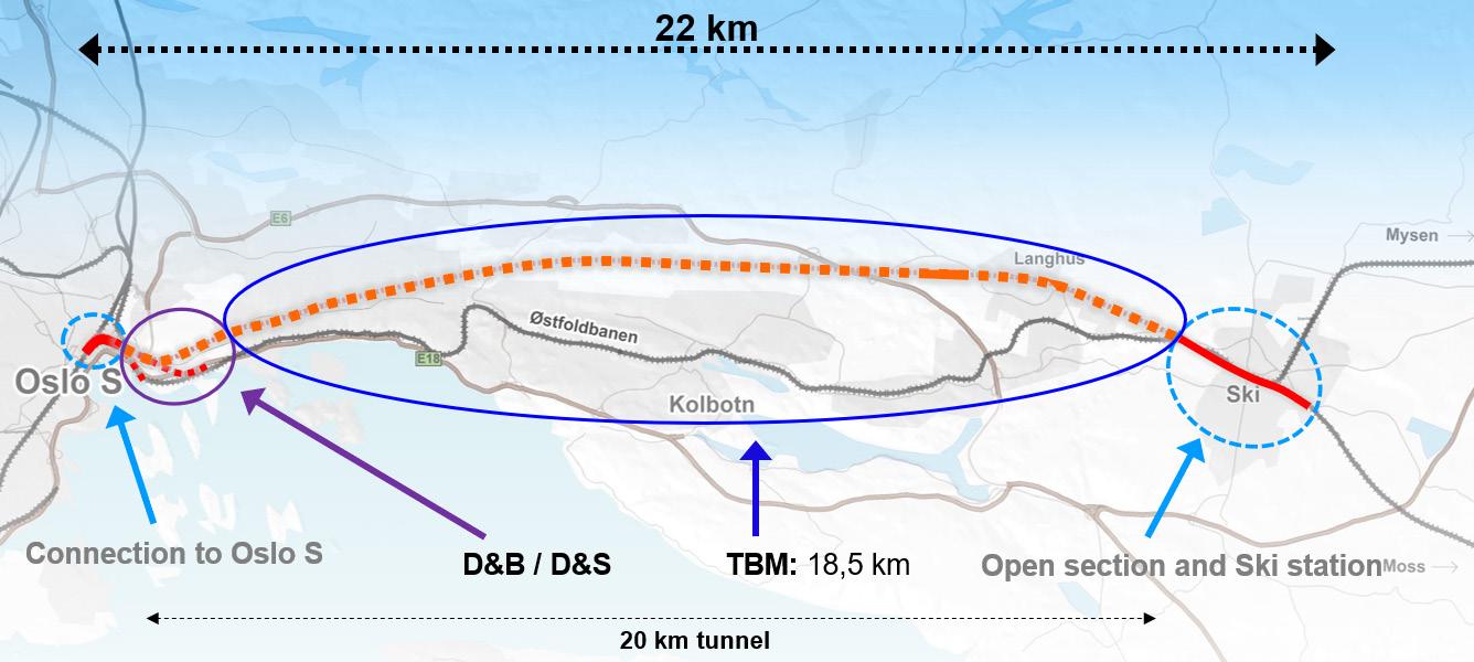
Figure 5-1: The Follo Line project was divided in four sub-projects for the performance of the civil work.
Since the signalling installation is continuous across the sub-projects, this was defined as separate contracts, covering the entire Follo Line.
The contract strategy was based on a risk-sharing model, where unforeseen uncertainty and risks associated with the geological conditions should be carried by the client. Apart from this, the Follo Line project was well defined, enabling the use of large Design and Build EPC contracts. Design and Build EPC contracts are dominant in the private industry, both in Norway and internationally, and are increasingly used for public infrastructure projects worldwide. This type of contract was decided to be used for the performance of the Follo Line project. The main EPC contract key features are listed up below:
• Contractor has full responsibility for the design, procurement and performance including progress, quality and guarantees.
• Fixed completion price
• A fixed completion date
• Liquidated damages for both delay and performance
• Security from the contractor and/or its parent
• Large caps on liability
• The contract regulates the ability of the contractor to claim extensions of time and additional costs
• Fewer contractual interfaces.
The level of definition of scope was deemed to be very high and this determined the choice of contract as being predominantly Fixed Price with possibility for variations.
Figure 5-2 below illustrates the principle.
Figure 5-2: Principles for effects related to different kinds of contracts.
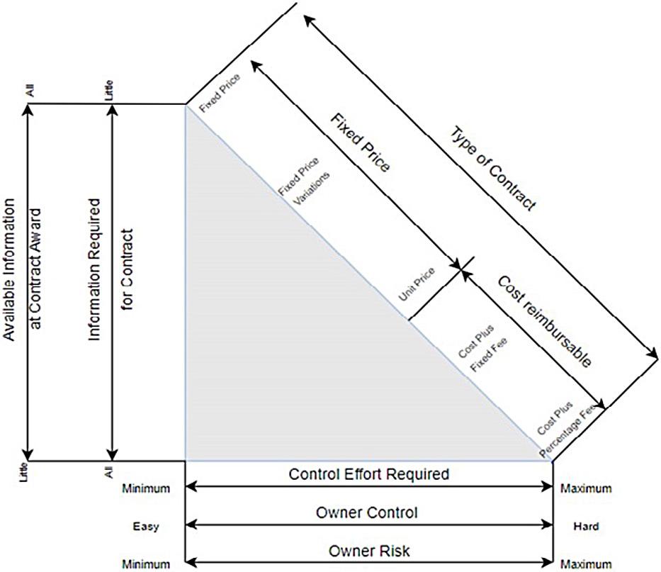
Although the choice of Fixed Price with possibility for variations type contract anticipates a lower level of client control, the client needs to be aware that under such contracts, the interests of the parties is not always totally aligned. The normal risk being that the contractor is seeking cost efficiency within the Contract specifications and the client is after best quality.
Accordingly, the client’s organization must still have a high focus on follow-up of quality and HSE. Inevitably, differences of opinion can arise between the contractor and the client in respect of quality requirements and interpretation of technical requirements. It follows that the client cannot avoid the risk for commercial issues/discussions arising during the contract period and the need for being properly resourced to deal with such issues. The chosen contract strategy with English as contract language and large contracts, made it more interesting for foreign contractors, but this was also recognised as a particular risk in relation to contractual interpretation and understanding.
For the engineering, procurement and installation of the signaling system, the client’s previously established frame agreements were used. For the connection to Oslo Central station, the existing signaling system for that station had to be installed in
the northern part of the Follo Line project. For most of the tunnel and for the sub-project south of the tunnel, including the extension of the station at Ski, a new electronic signal system, prepared for ERTMS are installed.
Comparing the reduced complexity of the Follo Line project tunnel scope for civil and railway technology, with experience from the EPC contracts in the Norwegian oil and gas industry and conditional on being able to identify contractors with the necessary relevant EPC and interdisciplinary competence, it was decided to include both civil work and railway technology for the entire tunnel section (excluding signalling) in the contract for the TBM excavation.
This EPC philosophy was also applied for the two contracts at each end of the tunnel, respectively the connection to Oslo Central station and Ski.
During pre-qualification phase there was a high focus on ensuring that the interested contractors/ Joint Ventures had the necessary experience, solidity and capability.
Table 5-1 below shows the original contract strategy for the Follo Line project, divided in four main EPC contract lots, in addition to the two contracts for the signaling system.
The tendering process for the two tunnel contracts and for the Ski contract were successful in respect of achieving bids which were fully compliant offers from the market.
EPC Contract No.2, the northern 1.5 km section of the 20 km long twin tube tunnel and a 1.7 km long section for relocation of the inbound existing Østfold Line, was awarded to the Italian contractor Condotte in February 2015. This part of the tunnel excavation was to be performed by a combination of drill and blast and drill and split methodology.
EPC Contract No.3, the 18.5 km long tunnel which was to be excavated by four TBMs, was awarded to the Spanish/ Italian joint venture between Acciona and Ghella (AGJV) in March 2015.
EPC Contract No.4, the open line south of the 20 km long tunnel and a total re-building of the station in Ski, was awarded to the Spanish company Obrascón Huarte Lain, OHL, in August 2015.
The competition for the EPC Contract No.1 for the connection to Oslo Central station was cancelled in 2015 due to lack of competition. The work was split into three contract packages:
• One EPC contract for civil works, which was awarded to the Italian contractor Condotte
• Two contracts for railway technology awarded to the Norwegian contractors Infranor and BaneService.
These three contracts were signed in December 2015.
Due to financial problems and the filing for bankruptcy protection of the Italian contractor Condotte, Bane NOR terminated the two contracts, EPC Civil Oslo S and EPC Drill & Blast (the northern part of the tunnel), in January 2018.
The remaining scope of work has been handled by taking over Condotte’s subcontracts for engineering and critical construction, together with the award of four new construction contracts for the remaining civil work, three for the connection to Oslo Central station and one for the drill and blast/ drill and split sub-project.
Risk sharing was based on the following principle:
Client (The Norwegian National Rail Administration, now Bane NOR) owns the geological and regulatory risks to the extent not defined in the contract and
contractor owns the design/ procurement/ execution/ productivity risks to the extent defined in the contract.
As the contract values (NOK) of the Follo Line project were more than eight times greater than previous Norwegian National Rail Administration contracts, it was decided that the contract standards (terms and conditions, compensation principles, etc) had to be reconsidered to reflect this situation.
The Norwegian oil and gas sector had, as a joint effort between the clients (oil companies) and the construction industry, developed successful large EPC contracts (NTK2) with well-balanced risk sharing principles and it was decided to apply these principles to the Follo Line contracts.
One particularly attractive aspect of NTK is that it encompasses administrative conditions which require that disputes related to scope, cost and schedule be dealt with on an ongoing basis to avoid the risk of building up large general commercial claims at the end of the contract phase. Both parties have benefited from this approach.
The Follo Line project team developed an adapted version of the NTK, in the English language, which was used in the EPC contracts. Non-oil and gas related issues such as ground conditions and railway specific risks were addressed.
The TBM tunnel contract contained in the range of 10 000 pages, of which more than 5000 pages were The Norwegian National Rail Administration’s Technical Guidelines/ rules.
Client provided raw data in the form of a Geological Data Report which included results from the geological investigations that had taken place in advance of the issue of the invitation for tenders, including the cores that had been drilled along the tunnel alignment as well as other site specific surveys, such as in the spoils deposit and rig area and information from laboratory tests. contractor had to conduct its own further investigations if deemed necessary and assume risks for same.
More specific information regarding geological investigations, which have been performed are described in Chapter 3, “Pre-construction planning and geological investigation”
The pricing format was predominantly based on a 2 NTK: Norsk Total Kontrakt (Norwegian Total Contract («EPC»)
Fixed price (Lump Sum) philosophy with rates for variations. Risk sharing conditions related to unforeseen ground conditions, volumes of pre grouting and deposits of spoil to offsite locations were catered for. Tenderers were allowed to price in both Euro and Norwegian Kroner.
To reduce the client’s risk in case of contractor’s performance and/or bankruptcy, the four tunnel boring machines and their associated equipment were the property of the client for the duration of the TBM excavation. On completion of the TBM excavation, the ownership of the four TBM’s and associated equipment were transferred to the contractor at a pre-agreed price established in the contract.
Lessons learned Experience achieved from using the NTK EPC contract format for the performance of the tunnel of the Follo Line project compared to former experience with unit-price contracts can be summarised as follows:
• Establishing the contractor as the single point with responsibility for the design, engineering, procurement and construction process has been a positive experience.
• The contractor has been allowed and motivated to make optimum use of its resources and experience.
• The follow-up of safety and quality require a competent team within all the disciplines. This is similar to the requirements under unit-price contracts.
• The obligation to solve scope, cost and schedule issues as they occur has been very positive. Both parties have had to address such issues at an early stage when the facts are available, and
the relevant personnel are still at site. This has avoided the risks associated with difficult and complex large commercial claims at later phases in the project.
• Especially in an EPC contract it is important to allow for enough engineering time before the actual construction works starts. And once the engineering is finished, it should be frozen and not changed again.
• The responsibility for the EPC internal interfaces has worked well, with the respective contractors having a clear understanding and authority to manage same.
• The external interfaces (different contractors) are greater challenges and the client needs to be prepared to involve itself in the management and coordination of these.
• In a Fixed Price EPCcontract, the contractor undertakes a higher risk which includes quantities, internal interface coordination of all activities and Subcontractor performances. In addition, there are liabilities associated with delays (LDs) and guarantee work, which in the TBM contract are capped at 5% of the Contract price. This level of risk is reflected in the price.
• The model for compensation of ground condition variations shall be based on undoubtable input data and shall incorporate specific procedures to calculate it.
• The use of PRIME (Project Integrate Mediation) principles was not considered successful. Instead, the approach should be to ensure that the project teams, from both Parties, are staffed with experienced and competent commercial personnel to deal with commercial issues.
• Investment and attention to understanding cultural differences is important and cannot be underestimated or overlooked.
The EPC TBM Follo Line project’s objective and policy was to strive for the achievement in obtaining zero harm to everyone and everything both internally and externally. The policy served as a guideline and foundation of the OH&S work and was mandatory to be followed by all. The performance of the project should at all time guaranty the safety for all personnel, both internal and external, including the communities surrounding the project.
AGJV defined the following objectives for the project to support the vision of zero harm, covering both active and proactive objectives and targets:
• Provide a safe working environment that resulted in no injuries
• At all time, work towards having zero incidents.
• Aim for parent client’s Commitment (Zero Harm).
• Facilitate and maintain effective communication regarding health and safety between all stakeholders in the project.
• Provide a workplace environment in which all employees could consult and participate in matters relating to project health and safety.
• Encourage to report all accidents/incidents and near misses.
• Reward safety.
• Give high priority to safety, in order to protect life, health, property and environment.
• Deliver compliance with the laws of Norway, internal and international standards, in addition to requirements from client, supporting Bane NOR´s vision of zero harm.
• Achieve continuous improvement in OH&S performance.
• Establish objectives and targets; measure, appraise and report OH&S performance.
• Protect the environment and prevent pollution.
• Safeguard the interests of neighboring local communities.
AGJV´s Senior management were fully committed to OH&S and adopted a visible leadership role. This policy was developed and enhanced by visible leadership that started at senior management level and cascaded down to supervisor level and included
leading by example. Proactive target setting that involved consultation with staff and contractors and was driven by individual and team performance appraisal.
The Follo Line project was, during the construction period, the largest transport project in Norway. Workers from 62 different nationalities around the world have contributed to the success and positive progress.
The senior management team was an international team composed of highly skilled and motivated individuals, working towards achieving a unified goal of creating company culture within an international environment.
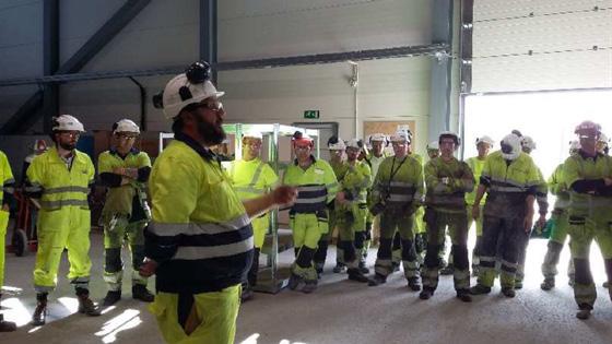
Multicultural Workshops, OH&S handbook translated to most relevant languages of the project (Polish, Portuguese, Spanish, Italian, English). Bane NOR collaborated subcontractors and their safety representatives used to gather to discuss and identify risks or difficult challenges that potentially poses a danger to the health and safety of the workers.
Induction courses and OH&S training Training was important, and to ensure that safety was in complains with the superior goals of the project, all workers had to conduct a mandatory safety course. The aim of the course was to highlight and ensure that all personnel was familiar with the hazards associated with the work they were going to do and the mitigating measures and tools they could use. New work environment is always a risk to any worker, hence having training ensured that they understood the risk and what to do in an event of an emergency.
Pre-shift meetings with the teams conducted by the management before the work commenced, was arranged as small awareness meetings as well as a tool for transmitting information related to health and safety. The goal of the crew talk was to allow and ensure that the workers actively took part in the safety work, and to make all workers understand that the mitigation measures and controls were in
place to reduce the risk in the workplace to “as low as reasonably practicable” (ALARP) level.
The project involved multiple phases of construction and production activities, all associated with different risks and potential dangers that the workers could be exposed to. During some occasions, the work seemed to be performed without necessary mitigations to prevent accidents. In other occasions, a row of different incidents happened during the execution of the work. To stop such unwanted trends and avoid a serious accident to occur, the line manager arranged Safety time-outs. Then they took a short meeting with the working crew to explain the importance of practicing a good safety attitude during the performance of their work. During this Safety time-outs, the line manager high-lighted specific risks of each task, and informed about near misses with previous activities, in order to enable the workers to understand the importance of conducting their work in a safe manner.
After these Safety time-outs, the frequency of incidents and near misses were reduced, which demonstrated the importance of using this tool, when needed.
Toolbox meetings were arranged as awareness meetings, and they were conducted by all departments. They were managed by AGJV OH&S department by issuing certain topics that the teams should discuss to strengthen the work-site safety and the safety environment of the workforce. The composition of the topics arised either by general concerns, or as specific concerns made by discipline department within AGJV or Bane NOR. In some cases, they were arranged as results of previous incidents.
Weekly safety rounds were held to ensure that the work-site safety was complied with and to detect unsafe conditions on site. This unified safety inspection was conducted with both safety- and management representatives from AGJV and Bane NOR, in addition to representatives from the subcontractors.
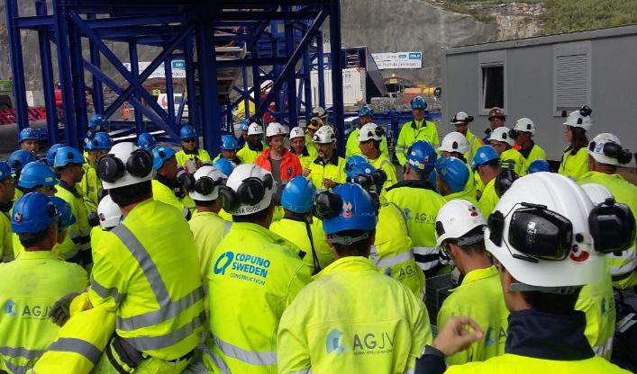
During the safety rounds, different areas within the construction-site were visited. The safety rounds were always completed with a specific safety-meeting after the inspection. In this meeting, a summary of all the findings from the different areas were given, and actions, in order to improve the safety were discussed and agreed. Other topics related to both safety and environmental issues were also discussed, and relevant actions were identified and agreed. In addition, cases from the previous safetymeetings were followed up.
AGJV established a system for reporting, analyzing, and follow-up of unsafe conditions and positive observations. Workers could report observations anonymously.
All kinds of findings, which could result in small incidents or serious accidents were reported on special Safety Observation Cards (SOC form) and issued through a deviation system, organized by Bane NOR, called Synergi. As a part of the registrations, actions taken to solve the observations were also registered. All the registrations were followed up in specific weekly meetings between AGJV and Bane NOR.
All the registrations were available for Bane NOR personnel and those who resulted in different kinds of accidents, were reported to the top management of Bane NOR.
Figure 6-3: Safety Observation Card (SOC).
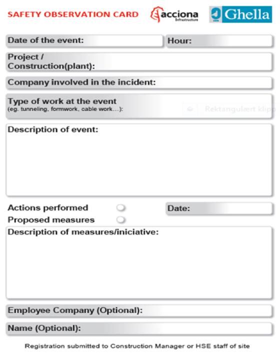
To strengthen the safety culture within the organization, AGJV implemented programs aimed to influence and improve safety behaviors of the workforce and the line managers.
The leader program (Proyecto Lidier) is a program aimed at strengthening the leadership through improving behaviors by applying modifications to the work. The purpose by implementing the program, was to ultimately alter the safety attitude by making the safety leadership more visible through direct interaction with the workforce. This also allowed AGJV to transmit their company policies to ensure an implementation of a positive and healthy safety culture throughout the organization. AGJV adopted the program to strengthen the safety culture of the middle management in the project. The program was known as the BBS4YOU-program.
Figure 6-4: Corporate conduct change program.
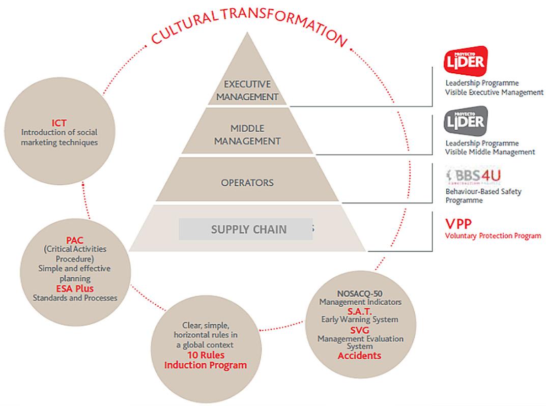
The Behavior Based Safety or BBS4YOU program was an application to improve and monitor the workers vision on safety in their daily work. This application contributed and strengthened the safety culture and collective responsibility of the whole workforce in the project. Regularly, the best teams who fulfilled specific requirements related to safety behavior, were nominated, and a winner was awarded a price. The management of both AGJV and Bane NOR took part in the award and gave speeches to honor the winner and highlighted the importance of taking responsibility for always improving the safety at site. The goal for both parties was that all the workers should perform the work every day in a safe way and without being affected by any accident.
5S is a system for organizing so work can be performed efficiently, effectively, and safely. This system focuses on putting everything where it belongs and keeping the workplace clean, which makes it easier for people to do their jobs without wasting time and / or risking injury. AGJV adopted the 5S methodology to rise the standard on site workshops and construction sites.
Figure 6-7: Examples of different campaigns arranged at the construction site.
To continue improving and strengthen the safety culture within the organization, AGJV organized safety campaigns during the different project phazes to raise awareness on work site safety.
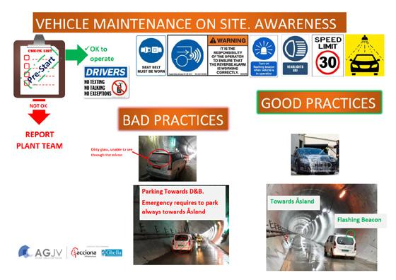

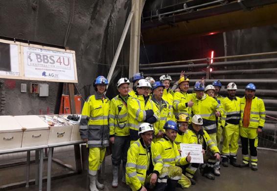
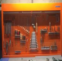
Safety has during the entire construction period been priority number one for Bane NOR. Their organization has, within all levels, had a close cooperation with the contractor, AGJV, in order to prevent serious accidents at the construction site. It has been a goal for both parties that everybody shall return safe and uninjured from work every day.
All near-misses and all kinds of accidents have been reported. The data have been analyzed in order to identify eventual trends or sources for accidents and based on this implement mitigations to avoid new cases to occur.
Both accidents which has resulted in sick leave, defined as H1, as well as accidents where it has been possible to continue to work, H2, has been counted.
Figure 6-8: Distribution of the different H1-incidents at the Tunnel subproject at the Follo Line project.
In Norway, the following definitions are used as Personal injuries values:
H1; Lost time injury refers for incidents/ accidents pr. 1.000.000 working hours which result in a sick leave
H2; The number of cases pr. 1.000.000 working hours where the employees return to work after sustaining an injury. First aid cases and workers who perform alternative work are also counted within this category.
Personal injuries values for the tunnel part of the Follo Line project counted from June 2015 to end of July 2021 are:
H1: 4,13 and H2: 12,50
As shown in the illustration below, the total number of injuries, which have resulted in sick leave (H1-accidents), represent huge varieties and they are distributed all over the body. The majority of them can be categorized as non-serious
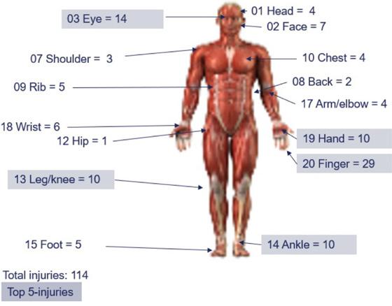
The Follo line EPC TBM project emergency concept was based upon risk analyses, emergency preparedness analyses, and workshop meetings with the Emergency Services.
The emergency plan for the project aimed to respond as fast as possible in a coordinated and efficient way, to minimize the human and material consequences that might have arised from any emergency scenario (work accident, fire, explosion, etc.).
At Åsland construction-site, the access control sys-
Figure 6-9: The main access to Åsland construction-site.
tem monitored inbound and outbound traffic of both persons and vehicles. In addition, the HSE-card from Norwegian Labour Inspection Authority was used as access card for all employees working at the Åsland construction site. The gate was manned around the clock.
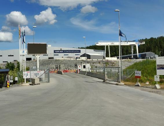
An integrated tracking system was installed in the tunnel system. The system consisted of personal tags for everybody who should enter the tunnel system and readers installed to monitor areas where the personnel were in the tunnel at any time. It was mandatory for all the workers and visitors to wear a tunnel tag during their stay in the tunnel.
The data was registered in a server and accessible in real time from a computer located in the Tunnel Control Centre (TCC) outside the tunnel.
Figure 6-10: Tunnel tag.
Figure 6-11: The Tunnel Control Center (TCC).
The TCC was allocated as command center in case of emergency.
All communication at Åsland site was supported by a redundant optic fiber system. Communication systems in the tunnel was UHF-radios, Wi-Fi and fixed IP-phones, all supported with battery backup. In addition, the national emergency communication system, “Nødnett Tetra”, was used for communication for the Emergency Services.
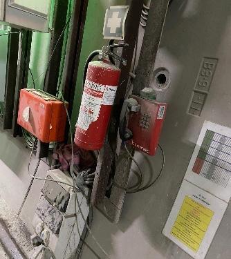
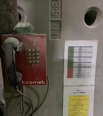
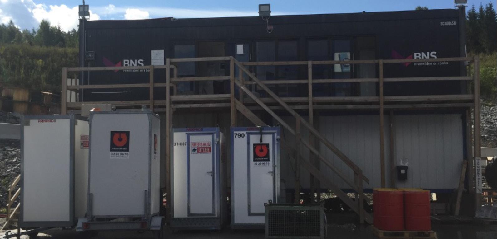
Illumination levels had an average of 30 lux in walkways and average100 lux in general working areas.
Emergency illumination with backup batteries was installed along the tunnels in a maximum distance of 50m to allow safe exit from the tunnel. The capacity of the batteries were minimum 120 minutes, and this was assumed to be sufficient in order to allow persons in the area to take appropriate action without danger.
Color code to show different installations in the tunnel were established. Fire-fighting equipment were marked with red-lights, and all the exits and emergency points were marked with green lights.
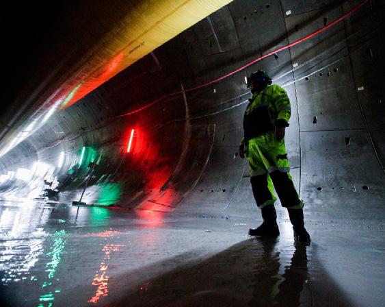
Evacuation alarms were installed every 480 m, located near the cross passages. In addition, evacuation alarms were installed in all access tunnels and in the northern interface area close to the Connection to Oslo Central station sub-project. The alarm was visual with a blinking light and equipped with a sound alarm. It was activated and deactivated manually, only from the TCC.
The water supply from the surface to the tunnels had a total flow rate of min. 17 l/sec at 8 bars to each tunnel. This rate was communicated and agreed with the Emergency Services.
Hydrant connection points with a standard “NOR Lock 1” coupling attached to the industrial water was installed at every 125 m throughout all tunnels as maximum.
Self-rescuers were available for all persons working in and visiting the tunnel. The operation time of the self-rescuer was 60 min with 35 l/min breathing minute volume.
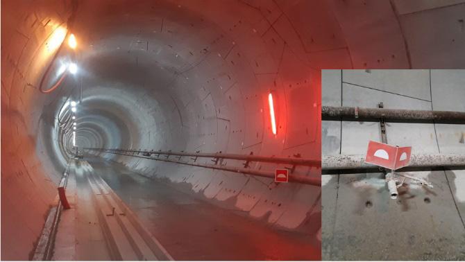
At fixed work locations, as for example cross passages and caverns, the self-rescuers for the whole crew and visitors were stored in fixed special boxes.
On the TBMs, the self-rescuers were stored in a fixed special box located on the TBMs backup.
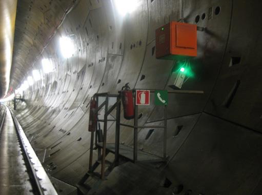
In the man rider / bus used for transportation of the crew, self-rescuers were stored in special fixed boxes.
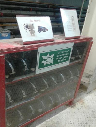
All the cars driving into the tunnels were also equipped with the number of self-rescuers corresponding to the number of passengers allowed, including the driver.
Emergency or safety points were allocated at every cross passage. The points contained a blinking light and a signal horn for the evacuation alarm, a phone with battery back-up, a first aid kit and 6 kg ABC fire extinguisher.
Fire extinguisher (ABC) and first aid kit were mounted in all vehicles. The driver was responsible for the presence of the fire extinguisher in the vehicle. CO2 fire extinguishers were installed at main electrical installations. Each MSV had an automatic and/or a manual fire extinguishing system.
The TBM’s were equipped with automatic “Stat-X” Potassium Carbonate aerosol fire suppression systems.
These systems covered the emergency generator, the hydraulic power pack, the main transformers, and the main electrical cabinets.
Figure 6-17: Emergency sketch for the TBMs.
Emergency preparedness for the TBM excavation phase was a very crucial period for AGJV and Bane NOR, with very limited evacuation options in terms of fire, smoke and other situations that posed a risk to health and safety of the TBM and tunnel personnel.
As a preventive measure, refuge chambers were used during the tunnel excavation. One chamber was installed on backup 1 of each TBM and on an emergency MSV parked behind each of the 4 TBM’s.
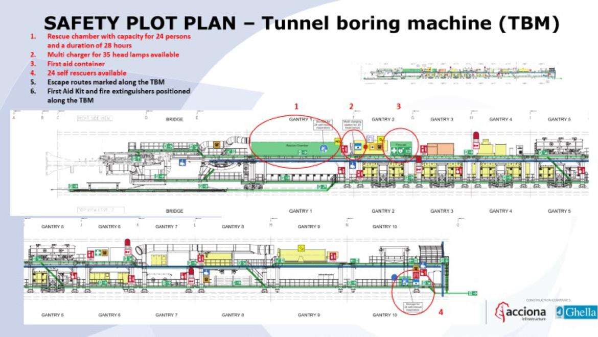
Additional refuge chambers were allocated for works associated with the excavation of cross passages before breakthrough were achieved. They were also allocated during the excavation of the escape tunnel and additional civil works.
The design temperature of all the chambers in case of a fire was 60°C for the full duration of the 28
hours. It was based on the DACH guidelines and so exceeding the requirements of EN16191.
The capacity in the refuge chambers were 24 persons and the operation time was 28 hours.
The refuge chambers were divided into two compartments. One was the airlock and the other was the main compartment where the workers could stay, in case of an emergency situation. This part was equipped with an air filtration system called breathing protection unit or BPU for short, which filtered out all toxic fumes that was brought in from the tunnel. In addition, the refuge chambers also had a cooling chamber to provide fresh circulation of air, a communication system, air measuring devices and first aid kit equipped with wounds treatment, defibrillator, stretcher, eye washer, drinkable water, and meal ready to eat.
Figure
Figure
Figure
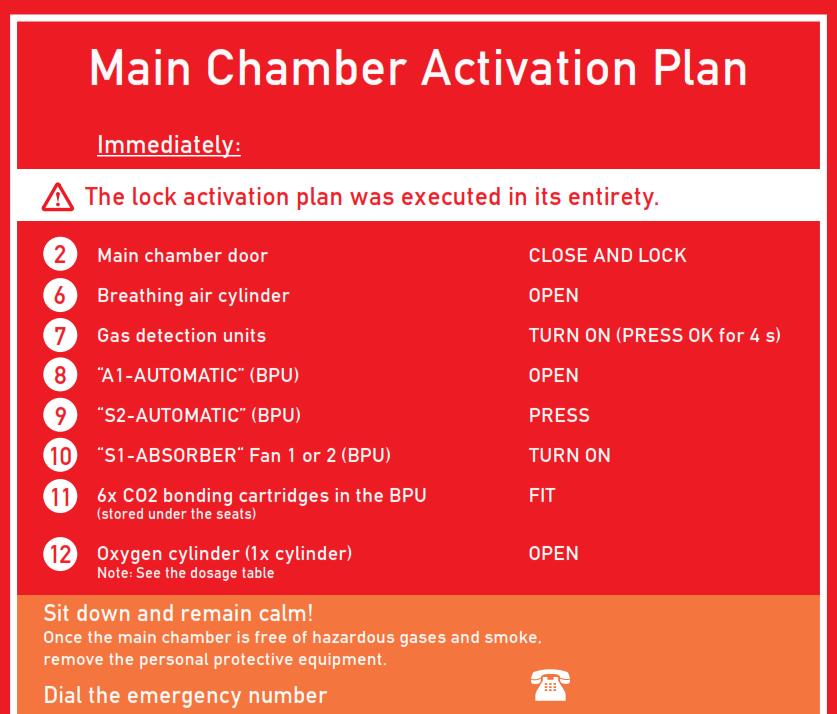

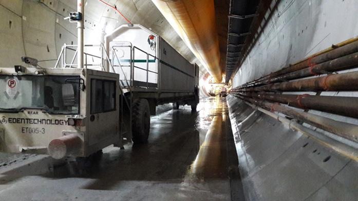
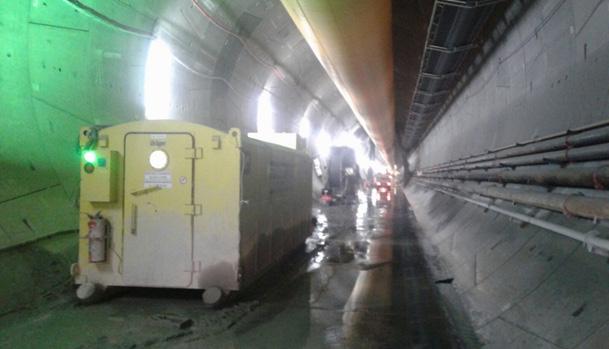
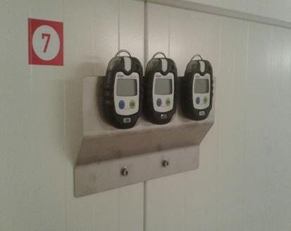
All personnel working on the TBMs, including some of the those working in the tunnel, were given an operational training to activate the chamber, but in any case, the activation instructions could be found on the refuge chamber wall close the BPU and was in different languages.

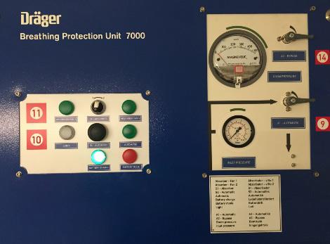
The main concept for evacuation in the Follo Line tunnels was based on the principle of self-evacuation through the smoke free non-incident tunnel.
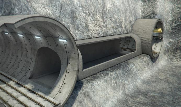
The cross passages at every 480 m served as egress from the smoke contaminated incident tunnel to the smoke free non-incident tunnel which was the incident free tunnel or the escape tunnel in the first
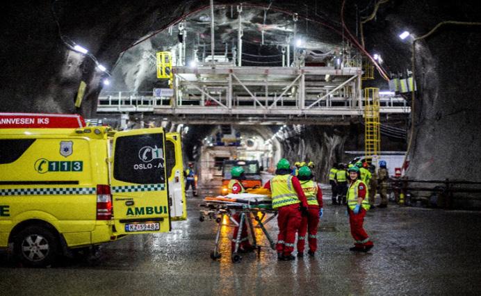
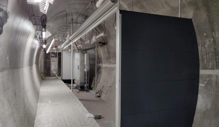
2.8 km of the north tunnels. The cross passages were equipped with doors or curtains for air and smoke separation between the tunnels during all construction stages. The length of the cross passages are mainly 25 meters and consists of a free corridor for emergency alongside a space reserved for electrotechnical equipment which were installed during the construction period.
The emergency preparedness plan was implemented in the organization through induction courses, training, toolbox talks, exercises, and informative meetings with the Emergency staff. The plan was based on a combination of handing out of instructions and of specific training for those involved in the emergency organization.
With the scope to train and check the status of the ability to handle an emergency for the different key personnel at the Åsland site, Emergency response training was conducted on a regular basis.
Tabletop and full-scale exercises were conducted in close cooperation with the Emergency Services, which also gave support during the entire execution of the project.
Emergency Forums on a management level were established at an early stage, to plan and discuss the upcoming activities, possible interferences with adjacent projects and relevant topics related to emergency preparedness.
Training and evacuation exercises were conducted with the Emergency Services related to how to handle incidents in the TBMs and in the rest of the tunnel system.
Figure 6-30: Evacuation exercise with cooperation of public Emergency Service.
Figure 6-31: Evacuation exercise on the TBM with cooperation of public Emergency Services.
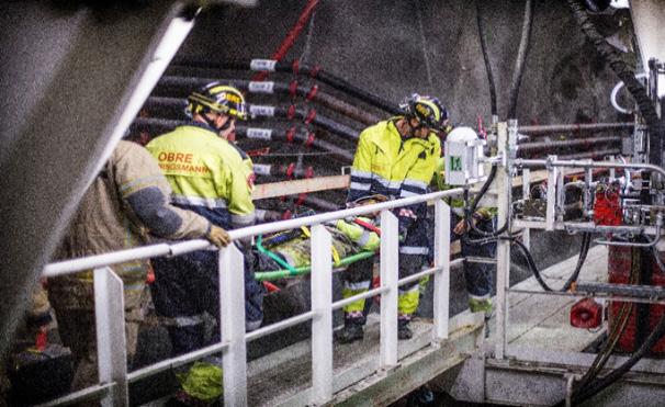
A design for temporary ventilation system during the TBM section of the Follo Line EPC TBM project was developed.
The TBM excavation started in a rescue tunnel midway in the main tunnel. This cavern was accessed from the working site Åsland by two adit tunnels about 1 km long. The entire tunnel system is described in more details in Chapter 19 “Safety concept for the operational phase”. The works required a mechanical ventilation system which ensured the occupational health requirements, fire safety and the technical functionality of the underground installations, both in the heading and the in the adit tunnels. A comprehensive design of this temporary tunnel ventilation system was required in order to cover the varying ventilation needed during the different tunnel construction stages.
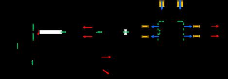
The concept of the ventilation of the TBM tunnels was based on circulation maintained by jet fans in the adit tunnels South and North. The air flowed from the Adit South to the Adit North by passing through the rescue tunnels. In order to have minimum contamination of the incoming air, all traffic in Adit South (=air intake) were going downhill with minimum emissions from the vehicles, and all traffic going uphill, including spoil conveyors, were located to Adit North. So that the traffic followed the same “one-way” flow as the airflow.
The fresh-air was blown into each of the four tunnels, where the TBM excavation took place, by large ventilation ducts. The exhausted air was blown from the TBMs, back to the rescue area and then out via Adit North.
After finishing the TBM excavation, the tunnel system had openings in each end. Then, the ventilation system was changed accordingly.
Figure 6-32: Sketch of the ventilation concept after the TBM excavation phase, when connection to other parts of the tunnel system had been established. By curtains in the northern part of the tunnels, the air was directed out via the access tunnel at Sydhavna.
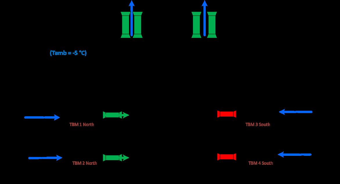
The Escape Tunnel, which handle evacuation from the two Follo Line tunnels in the area, where theses tunnels are crossing each other, was excavated by drill & blast. The ventilation system of this Escape Tunnel was completely separated from the Adit ventilation during the excavation phase. Fresh air was supplied to the Escape Tunnel through a ventilation duct by means of a supply fan located on the surface. A fan for blast fume extraction located in the escape tunnel, extracted the blast fumes from the Escape Tunnel, and pushed them through a separate ventilation duct to the surface.
When the TBMs started to operate, the TBM tunnels were ventilated through flexible ducts with a diameter of 2.8 m, located in the crown of the tunnels, which suppled air to the TBM’s. The fans for all four TBM’s were in the Adit extension south and took fresh air coming in through the Adit south.
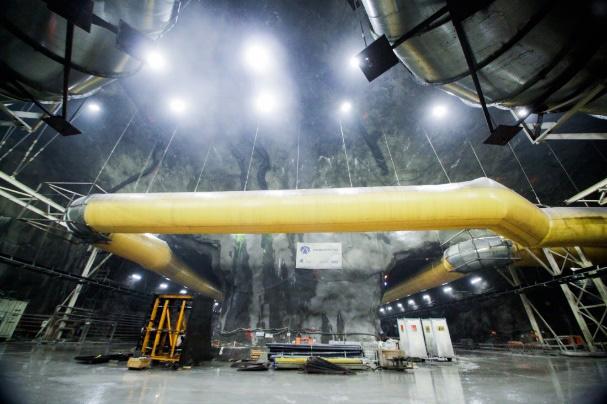
A large portion of the fresh air arriving at the end of the TBM backup was then moved further forward to the front of the TBM through the fan and ducts of the TBM secondary ventilation. From the front of the TBM, a portion started flowing back through the TBM backup. The other portion of the incom-
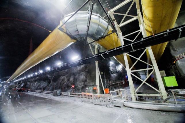
ing air was taken in by a separate circuit collecting the dust from the cutter head and from the TBM conveyor discharge area and returned into the main airflow out of the tunnel after passing through a dust scrubber.
Both airflows join within the backup area, and traveled through the tunnel, back to the portals of the TBM tunnels in the assembly caverns together with all leakage flows from the flexible ducting, which also ventilated the whole TBM tunnel.
Depending on the location of a fire, the fans had to be operated differently than during normal operation, in order to minimize the smoke-spreading underground, and help the evacuation of the crews. The fans on the TBMs were controlled by the TBM operator and generally switched off under a potential fire. The fans in the Adit-tunnels as well as the main TBM tunnel supply fans were controlled from the Tunnel Control Center (TCC) based on a matrix depending on the exact location of the fire. This matrix was provided as a part of the Fire life Safety report, designed for the project.
The fan control in the TCC should also help the Emergency Services to manage the ventilation in accordance with the required response, depending on the situation.
Bulkheads enabled to control the flow rates in the different branches of the Adit-tunnels and Transport tunnels were installed, following the design ventilation concept.
Figure 6-36: Ventilation duct in the TBM tunnels.
Figure 6-37: Sketch analyzed Fire scenarios after TBM excavation phase.
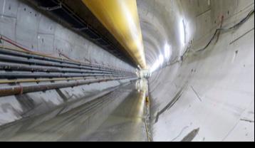
The main philosophy in the Follo Line tunnels emergency plan was to escape from the tunnels by using the nearest cross passage and then close the emergency door. People entrapped by a fire or toxic atmosphere should use self-rescuer.
In order to ensure that no smoke from one of the TBM tunnels could flow into the parallel tunnel, all cross passages were equipped with temporary bulkheads, which were later replaced with permanent walls and doors. This permanent separation ensured that the second tunnel always remained as a safe place for evacuation. The only time this separation
was breached was during blasting works in a cross passage that was already broken through.
In such a case, restrictions to other works (i.e. on the TBM’s) would apply since a safe evacuation path and access for Emergency Services to the TBM could be compromised in case of an emergency.
Is it a health benefit with the TBM method?
The health effect on tunnel workers with TBM method have not been in much focus. Minor studies have been conducted in recent decades, so when the Follo Line project was going to use four TBMs for drilling the tunnels, the National Institute of Occupational health (STAMI) saw an opportunity to
more thoroughly and to a greater extent be able to study what health benefits drilling with TBM could have. Earlier, STAMI had conducted a study in close cooperation with Bane NOR on the Ulrikken-tunnel project in Bergen. This tunnel was excavated by an open TBM. Now they saw the opportunity to do a similar study on a double shield TBM in The Follo Line project. The documentation of the study is included in Appendix I.
The samples taken from the health examinations during the study are still being analyzed and the final results are not presented yet. It is therefore too early to make a final conclusion about the exact health effects drilling with TBM may have compared to excavating tunnels by conventional drill and blast. But for sure, based on the analysis results from the exposure samples that were taken and the actions that were performed through the project to reduce the exposure, a positive effect have been measured. The exposure of dust for the workers who operated close to the cutterhead were reduced.
The test results gathered during drilling with the TBMs showed a difference in dust exposure between different groups depending on where on the TBMs or in the tunnel they worked. The longer away from the cutterhead, the lower the exposure.
The results analyzed so far also demonstrated that drilling with TBM gave significantly less negative dust exposure from diesel exhaust and rock dust than are created from conventional drill and blast excavation. The main reason for this is related to the use of conveyor-belt for the transportation of the excavated material all the way from the TBMs to the surface. This gives less pollution from exhaust from vehicles and less dust whirled up by the wheels.
It is still great opportunities for the industry to reduce the health impact for tunnel workers by focusing on further development of technical solutions and barriers on TBM. It lies a big potential to reduce the negative health effect of dust, by using a larger amount of time on the organizational barriers like mapping dangers, looking at methods for work operations in different groups, i.e., maintenance staff.
Finally; the awareness of each one of the workers, at all levels, knows what they can do to reduce the dust exposure in tunnel work.
Ulvestad, B. & Bakke, B. & Melbostad, E. & Fuglerud, P. & Kongerud, J. & Lund, M.B. Increased risk of obstructive pulmonary disease in tunnel workers, Thorax, 2000
Ulvestad, B. & Lund, M.B. & Bakke, B. & Thomassen, Y. & Ellingsen, D.G. Short-term lung function decline in tunnel construction workers, Thorax, 2015
Our tunnel experts deliver multidisciplinary services for tunnel and underground engineering projects around the globe, covering the entire lifecycle of a tunnel, from feasibility studies, ground investigations and geological design to fire and safety strategy.
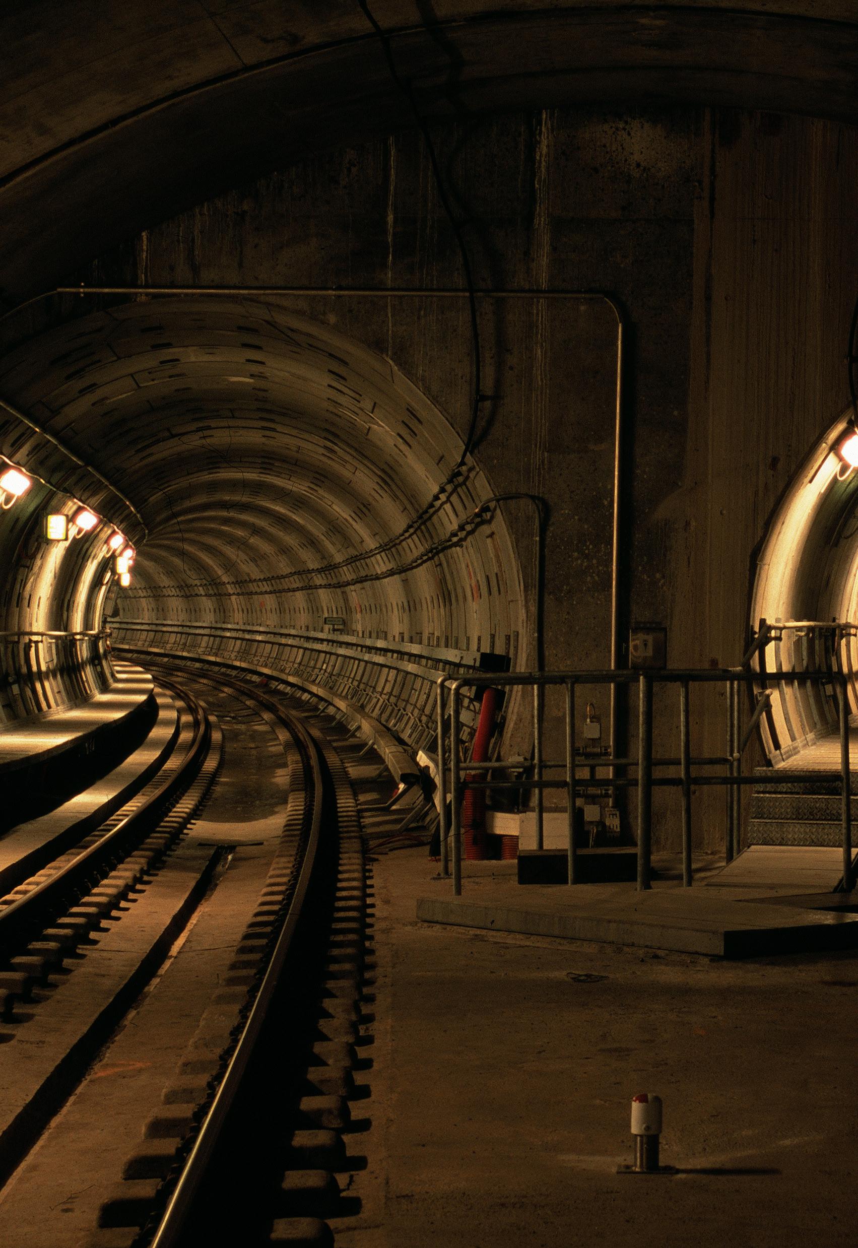
COWI is a leading consulting group that creates value for customers, people and society through our unique 360° approach. Based on our world-class competencies within engineering, economics and environmental science, we tackle challenges from many vantage points to create coherent solutions for our customers - and thereby sustainable and coherent societies in the world.
Before the excavation of the tunnel by four tunnel boring machines could start, the rig area had to be established, a feeder station had to be built and the drill and blast excavation of the access-tunnels, different logistic tunnels and the two large caverns for the assembly of the machines had to be finalized. All these preparation works disturbed the neighbours. In the period between September 2016, when the first machine set off, and February 2019, when the two machines heading south had their breakthrough, the TBMs passed under several densely populated areas. The TBMs set of from two rock caverns situated at the centre of the tunnel, two machines headed south for the regional town of Ski, and two machines headed north towards the capital Oslo. The operating hours were 24 hours a day, 6 days a week, with the exception of a daily maintenance shift of between 4-5 hours.
The large rig area was located in a rural area, with a limited number of neighbours close by. To protect these neighbours against noise from the construction activities, different kinds of mitigations were performed in advance.
One of the mitigations were to isolate the houses against noise by changing the windows. In some of the buildings, where the bedrooms were located towards the rig-area, new ventilation systems were installed.
Outside the buildings, the terraces were protected against noise by installation of noise-walls.
At the rig-area, outside the tunnel, the entire conveyor-belt was covered by a “box”, which, more or less, totally eliminated the noise. The 9 million tons of spoil was dumped in an in-door building, to protect the neighbours against noise from the 24/6 excavation activities. The covering of the conveyorbelt and the in-door dropping of the spoil, provided protection against exposure to rainfall and snow, as well. During the night, there were restrictions against activities which could provide noise above a certain level.
In order to minimise noise from the construction site, several additional measures were taken:
• The concrete factories were insulated with sandwich panels, and the vibrating chamber was completely insulated as a separate noise chamber inside the factory.
• Internal transport vehicles (MSVs) were custom made to generate less noise.
• Noise fences were established along the rig and spoil areas, and a noise barrier was built at the end of the spoil area.
• Site vehicles and factory cranes were equipped with white noise buzzing alarms instead of traditional beeping alarms.
Noise levels were modelled in advance and continually monitored throughout the construction period. Spot checks on equipment and processes were done routinely. Monthly noise calendars were prepared, showing the noise impact of the planned construction activities for the following period.
Initially, the project obtained a dispensation from the noise regulations for construction works from the municipality. Once the factories were established, the project was recategorized as an industrial site according to the noise guideline T-1442/2012.
Mitigations and communication with the neighbours were important tools to achieve acceptance for the 24/7 activities that took place at the rig-area during the establishment of the site and later during the excavation of the tunnels.
Before the TBMs started to bore, it was uncertain exactly how the structural noise would spread and affect the neighbourhoods located above or close to the tunnels. It was known from other projects that several factors, including distance, geological conditions and building foundation would affect the dispersal of structural noise.
Available data from other hard-rock TBM projects in Sweden and Switzerland showed inconclusive sound levels in nearby areas, from which a best- and worstcase estimate could be derived. This is illustrated in figure 7-1 below.
Fortunately, the first areas where the TBMs excavated below, was uninhabited and allowed for noise
measurements to be made before the machines reached more populated areas. Measurements were also performed in houses while the machines passed
under different neighbourhoods. See some of the results in figure 7-2 below.
Figure 7-1: Estimated structural noise levels based on data from other hard-rock TBM projects.
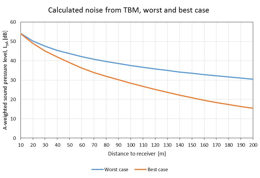
Figure 7-2: Best-worst case estimates compared with measurements of structural noise in buildings founded directly on the rock surface.
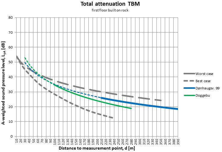
This provided greater certainty in estimated noise levels. The noise measurements resulted in three
3D distance between housing unit and TBM (corresponding with limits in T-1442)
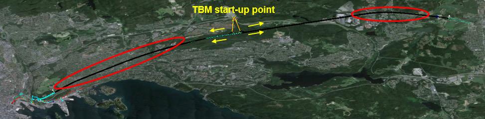
distance thresholds with their respective noise estimation as shown in table 7-1 below.
< 70 meters > 40 dB
70 - 120 meters 40 - 35 dB
120 - 200 meters 35 - 30 dB
To achieve an efficient excavation of the tunnel and due to the schedule of the Follo Line project, it was required to have a 24/6 production for the TBM-drilling. The estimates showed that the noise could exceed 30 dB within 200 meters from the TBMs. According to state regulations (Norwegian Environment Agency 2016), mitigation measures and corrective action must be implemented when exceeding 40 dB indoor noise in the daytime (0719), 35 dB in the evening (19-23) and 30 dB during the night (23-07).
There were approximately 5500 housing units located within 200 meters from the two Follo Line tunnels. Thus, a potential consequence was that several thousand housing units and all their inhabitants would need alternative accommodation, given that the TBMs operated day and night.
The additional noise measurements, made throughout the TBM excavation process, matched well with the original best-worst-case estimate. The main difference was that the noise level seemed to increase more than expected within distances less than 50 m from the TBMs. The effect that distance has on noise reduction is related to the speed of the P-wave in the rock. In the original estimate, the P-wave speed was set to 3500 m/s. In some of the areas where the rock was homogenous with more or less no
fractures, the speed of the P-wave was measured to be 4500 m/s. In other areas, with a higher degree of fractures, the speed of the P-wave was lower than 3500 m/s. There were also examples of intrusive dykes which transferred the structural noise better and over a longer distance than the surrounding rock. Seismic investigations are therefore recommended when estimating structural noise dispersion in different rock conditions.
In areas where buildings are founded on soil above the rock-surface, the thickness of the soil-package is also of huge importance for the transfer of the structural noise. The material of the building and on which level of the building measurements are made, must also be taken into consideration.
The key to work 24/7 close to populated areas was well prepared neighbour communication
The Follo Line project is the first tunnelling project in Norway to drill through several densely populated areas. It was estimated that approximately 5500 households with a total of 20 000 occupants could be affected by the structural noise from the TBMs during the excavation period. See the areas which would be affected by the structural noise in figure 7-3 below.
Several studies of the issue concerning neighbours and structural noise has been published during the TBM-period; see reference list for further details.
The strategy, to excavate 24/7 and compensate the disturbances of the neighbors by offering them alternative accommodation, was accepted by the health authority in the affected municipalities. The argument was that it was better to pass the different residential areas as fast as possible, mainly within a limited number of weeks, instead of exposing the neighbours for structural noise over a longer period. Well planned and organized communication was required to achieve acceptance for this strategy from the affected neighbours.
The TBMs’ progress was not constant, and it was therefore not possible to accurately predict when and for how long each neighbour would be affected by the structural noise. The fact that there were two pairs of TBMs, each with different advancement, made it difficult to know when, and for how long, a neighbour would be affected. If the two TBMs were close to each other, the neighbours would experience one distinct period of noise, while if the TBMs were farther apart, the structural noise would come in two bouts with a break in between. Planning therefore became essential.
A prediction model was built by using GIS (Geographical Information Systems) software for planning purposes. The model was based on a digital 3D-model including the tunnel alignment, and it was used as an important tool for the communication with the neighbours that were expected to be affected by structural noise from the tunnel excava-
tion. The terrain above the tunnel section had been mapped and was combined with geographical data from official authorities like cadastre data and number of inhabitants at each address point. In addition, information of the geological ground conditions was also linked to the model. The TBM progress was updated every day and made it possible to measure the real distance between the TBMs and the buildings along the tunnel section.
Based on the information from this model and the experience achieved from the migration of the structural noise through the different types of geological conditions, it was possible to calculate expected levels of structural noise that would affect the different buildings on the surface and to foresee how many neighbours that would be needing alternative accommodation in the near future. The 3D distance between each address point and each chainage-point in the tunnels was calculated, to which the prognosis could be adapted as the TBMs progressed. Each morning the contractor updated the TBMs’ locations based on chainage.
The housing units were grouped based on their distance to the tunnel line, which was based on the distance thresholds from the earlier mentioned noise-measurements: 200, 120 and 70 meters between the houses and the tunnels. A special category of housing units less than 50 meters from the tunnel was also added as these would be extra affected and needed close follow-up. Exactly how high the structural noise level would be within 50 meters was not known, but for certain above 40dB, which meant that the same mitigating measures were needed as within the 70 meters threshold.
Figure 7-4: Housing units located in different 3D-distances from the tunnels.
Figure 7-4 gives a picture of the number of houses located within the different distances from the tunnels.
The prediction model delivered two types of prognoses. The first type showed the quantity of housing units within the threshold distances from the TBMs for the nearest future. One prognosis was made for the northern section, another for the southern. This was used for planning a few months ahead and formed the basis for the pre-booking of hotel rooms.
Second, a custom-made application allowed for the querying of a specific address and returned the dates the TBMs would be entering and leaving the address’ 200-, 120-, 70- and 50-meter radius, respectively. This is illustrated in figure 7-5 below.
The model calculated five sets of dates, based on five different weekly boring advancement rates. To determine the most likely advancement rate, it was essential to consider the most recent advancement in the type of geological conditions the TBMs were operated in at the specific moment. This information was retrieved due to close contact with all parts of the TBM project organisation regarding the TBMs current status and any possible change in predicted advancement. Since the application calculated the exact distance between the queried address and
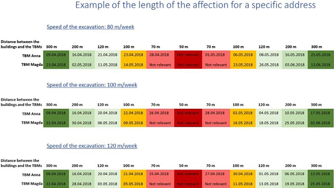
Figure 7-5: An estimation of when the TBMs would be operating within different radiuses for a specific address based on different progresses of the machines.
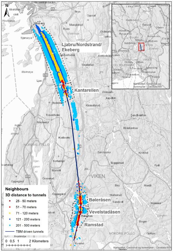
the TBMs, a prediction of the most likely level of structural noise could be made. The application was used in direct contact with individual neighbours to inform them about the TBMs whereabouts, which level of structural noise they could expect to be exposed to during the next days or weeks, and for shortening or lengthening of their hotel stays, if needed.
During the excavation under the first densely populated areas, it become clear that the public had a great interest in the TBMs’ daily movement. As a result, an interactive web map was launched for the public to use. The map showed the progression of the four TBMs, and their location was updated once per weekday. This is shown in figure 7-6 below. Users of the map could search for addresses within 500 meters from the tunnel and see the shortest 3D distance between the address point and the tunnel.
Between July 2018 and the end of February 2019, when the last TBMs broke through, there was an average of 119 daily viewings of the web map. During the weekends, when the map was not updated, there were noticeably fewer views than during the week. The day the two northbound TBMs had their breakthrough, the visitor number peaked with 972 views.
Given that the overburden was greater in most of the northern half of the tunnel, it is likely that the web map was used more actively by the neighbours above the southern part of the tunnel. It is also likely that several of the map’s users weren’t directly affected by the tunnel boring, but merely interested. There was a visible peak in map views the day an online news source for the construction industry published a short article about the web map’s existence, shortly after the map was launched, which reflects the general fascination of the Follo Line project by others in the industry.
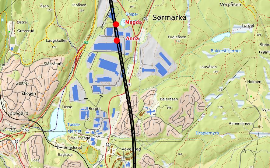
As a successful strategy for the Follo Line project, the neighbors were informed in due time before the TBMs were expected to approach the different areas along the tunnel section. Those who would be affected to structural noise levels exceeding the trigger values, especially during night, were offered alternative accommodation, mainly in nearby hotels.
Bane NOR’s goal in communicating with affected parties was to act like a responsible company taking sufficient consideration to the affected parties, communicating truly about the disadvantages from a knowledge-based platform. The policy was that most neighbours should be encouraged to stay at home for as long as possible to maintain their daily
routine, but that the offer of alternative accommodation should be easy at hand and arranged swiftly when they needed it.
A plan for communication with the affected parties was prepared based on Bane NORs communications policies, and the project stakeholder analysis. In the plan for communication with the affected parties, the tunnel path was divided into sub-sections. This is illustrated in figure 7-4 above. As seen in the figure, the northern half of the Follo Line was split into only two areas: Ljabru/Nordstrand/Ekeberg and Kantarellen. The latter is a geographically delineated area with valleys on each side, while the former is a large area which was not split up due to the density of the residential area with no natural breaks. In addition, the overburden was, more or less equal within the entire area, so it was not sufficient to split it up for prognosis areas.
In the south, topographic conditions divided the different neighbourhoods. This mirrored the definition of the sub-sections.
The neighbours within each sub-section received information and were invited to community meetings before the machines entered their area. The information measures were packaged and repeated for each subsection with relevant adjustments.
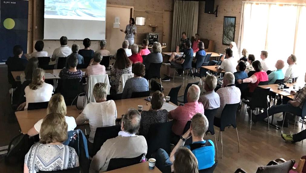
It was important to give the affected parties early warning of the disadvantages, to make it possible for them to prepare and make plans, in advance of the entrance of the TBMs.
During the TBM excavation period, 10 community meetings were held, as a cooperation between Bane NOR and AGJV, and each subsection of the tunnel path received written neighbour information pertinent to their own area. Other measures used were newsletters on the project twice a year, information by SMS, e-mail newsletters, social media, films, and personal contact by phone or e-mail. Neighbours were also invited to special events at the Follo Line information centre. For many affected residents, the interactive map was a very important source of information. Several neighbours commented that they used the map to estimate when to contact Bane NOR to ask for accommodation. The majority of the residents, who were in direct contact with Bane NOR, expressed that they wanted to stay at home as long as possible.
A registry of hotel bookings was kept, and later matched with the registry of neighbours and groups of neighbourhoods and their distances to the tunnel line. The number of neighbours who accepted the offer to stay in hotels while the TBMs were close to their homes varies between the neighbourhoods, as seen in figure 7-8.
The experience was that, in total, a limited number of neighbors accepted the offer to stay at a hotel while the TBMs passed the area where they lived, but there were variations.
There are a few possible reasons that so few inhabitants in the two northern areas, Ljabru/Nordstrand/ Ekeberg and Kantarellen, stayed in hotels compared to the southern areas. First, the overburden was higher in the northern section. Second, the northern neighbourhoods are more densely populated and thus has more traffic and other urban noise, which might mean that the structural noise was less noticeable. Third, the area in the northern part of the tunnel section with the lowest overburden, was the first populated area the TBMs bored under, and the experience of the structural noise was then not yet well known.
In areas where the distance down to the TBMs were between 120 and 200 meters, less than 10% of the inhabitants used the opportunity to sleep in more quiet environments. In some of the areas where the TBMs passed within a distance of 30 to 70 meters, nearly 70% wanted to stay at a hotel while the excavation took place under their neighborhood, but in other areas where the TBMs passed within a small distance, only 10 % accepted the offer. The general experience was that, in spite of the expected noise levels, most of the neighbors wanted to stay at home.
In the end of 2018, an invitation to a web-based survey was sent out to all the neighbours who had been in contact with the communications team. The survey sought to answer how the neighbours experienced communicating with Bane NOR during the Follo Line TBM excavation period. In addition to general background questions, it included questions about the experience of living near the TBM boring, and those who were offered a hotel stay as a mitigation measure were asked to evaluate the offer. The response rate was 49%, 269 responses from 552 invitations.
There are some weaknesses to mention regarding the survey:
First, because the survey invitations were sent out up to 1,5 years after the TBMs excavated under the first populated area, some respondents were asked detailed questions about non-recent events. Approximately half of the responses were from the areas which had most recently been exposed to structural noise from the TBMs.
Second, the survey invitations were only sent to neighbours who had given their email address when they were in contact with Bane NOR. Neighbours who only talked to the communication team on the phone without giving their email address were therefore excluded from the survey. This could
potentially affect some of the elderly who don’t use e-mail, but it is worth adding that a third of the respondents were aged 60 or above.
A total of 90% of the respondents stated that they had read the neighbour information. 86% of these stated that they had received it in their mailbox.
Contact with Bane NOR was mainly through e-mail or phone. The contact information was most often
found in the neighbour information (42,1%), newsletter (25,8%), on Bane NORs homepage (48,5%), multiple choices were possible. 11,2% of the respondents stated that they did not know how to get in touch with Bane NOR.
The response given by Bane NOR was rated by 84,7% of the respondents as good or very good. Se the result in figure 7-9 below.
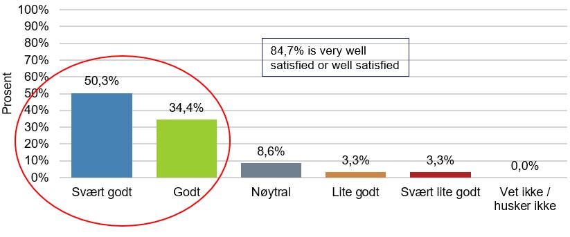
Most of the respondents contacted Bane NOR because they experienced noise or vibrations from the tunnel works (70,4%) or wanted information about alternative accommodation (62,2%).
44,5% of the respondents had experienced noise for longer than 2 weeks before contacting Bane NOR.
37,8% of the respondents waited 1-2 weeks before contacting Bane NOR.
In total 84,4% of the respondents assessed the communication with Bane NOR as very good (39,4%) or good (45,0%). 7,5% of the respondents assess the communication with Bane NOR as poor or very poor. This is shown in figure 7-10 below.
7-10:
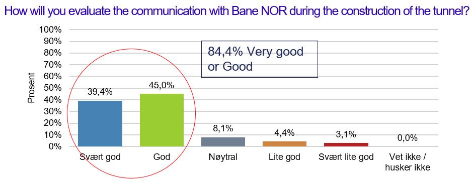
The survey also asked about how it was to experience structural noise from the TBMs. More than half replied that it was similar to the engine noise on a ferry, one third said that it resembled them of a washing machine or dryer. 25% of the respondents added free text answers, and deep humming sound was mentioned several times.
Kantarellen was the first neighbourhood to experience the structural noise. The TBMs heading north passed under this area during the summer of 2017, the lowest overburden was less than 60 meters in 3D distance from the tunnel, with several apartment houses directly above the tunnel path. Only 9 respondents were from this area, and only 29 hotel stays were in total booked for residents living in this area.
90% of the respondents read the neighbour information, and 75% of the respondents accepted the offer of alternative accommodation. 25% of the respondents, who turned down the offer of alternative accommodation, stated that they preferred to stay at home. 66,6% rated the communication with Bane NOR as good or very good. 71% of the respondents worried about the noise from the TBMs.
The next neighbourhoods in the northward direction, Ljabru, Nordstrand and Ekeberg had an overburden between 80-130 meters and the TBMs passed this area between august 2017 and September 2018. Of the 3300 households within a distance of 200 meters 3D distance or closer, only a small number needed hotel accommodation. 83% of the respondents rated the communication with Bane NOR as good or very good, and 79% of the respondents accepted the offer of alternative accommodation. Of those of the respondents who declined the offer, 43% stated that they preferred to stay at home. 75% of the respondents stated that they worried about the noise from the TBMs.
Bøleråsen was the first densely populated neighbourhood over the southern part of the tunnel, and the first neighbourhood with less than 50 meters overburden. The TBMs passed under this area between April and May of 2018. 95% of the respondents had read the neighbour information, and 51% worried about the noise from the TBMs. 90% of the respondents accepted the offer of alternative accommodation, and 84,4% were pleased or very pleased with the offer. Amongst those of the respondents who declined, 60% stated that they preferred to stay at home. The communication with Bane NOR was rated as good or very good by 89,7% of the respondents.
Vevelstadåsen was the second neighbourhood over the southern part of the tunnel. In this area we find the lowest overburden with 25 meters from top of the future rail in the tunnel to the terrain level of the nearest house. Because of an error in the questionnaire, Vevelstadåsen was not, for a period of time, given as an option in the question “Which neighbourhood do you live in?”. As a consequence of this, the responses included from Vevelstadåsen are in the results based on only on 5 respondents. All of these respondents accepted the offer of alternative accommodation, and 4 out of 5 assessed the communication with Bane NOR as good or very good.
Ramstad was the last neighbourhood in the southern part of the tunnel, and the TBMs passed under the area between September 2018 and November 2018. Also, in this area the overburden was below 50 meters, with houses located directly above the tunnel. Over a fourth (27,9%) of the respondents specified that they lived in this area. 99% of the respondents had read the neighbour information, and 42% worried about the noise from the TBMs. 91% of the respondents stated that they accepted the offer of alternative accommodation, and 96% of these were satisfied or very satisfied with the offer. 97,3% of the respondents assessed the communication with Bane NOR as good or very good, the best result of all the neighbourhoods. It is worth mentioning that in this area Bane NOR had a close collaboration with the board of the housing cooperation where the majority of the houses closest to the tunnel were organized. This collaboration contributed in a positive way towards the distribution of information, and Bane NOR received feedback from the board during the period of tunnel drilling.
Before the boring started, there were little data available regarding structural noise from other hardrock TBM projects, but luckily there was time for the Follo Line project to collect data before the TBMs closed in on populated area. For estimating expected levels of structural noise, several parameters must be taken into account, like distances between the TBMs and the buildings, the geological conditions, the foundation of the buildings and on which level in the buildings people have their living rooms and bed rooms. Hopefully the data presented here and in referenced articles can be of help to similar future projects.
When analysing the survey results and the registry of hotel bookings made by the Follo Line project, some tendencies seem clear. There seems to be a certain limit for how much structural noise the neighbours were willing to live with. On the day of
the guests’ first hotel check-in, the average distance between their address point and the TBM advancing towards it, was 194 meters. On the day of the last check-out from the hotel, the average distance was 244 meters.
This indicates that they wanted to stay at home as long as possible before moving to a hotel and then they wanted to stay at the hotel until they were certain that the noise level was at a comfortable level before moving back. These averages do not include the neighbours who opted to arrange their own alternative accommodation. This coincides with the results from the survey, where 44% of respondents said that they experienced noise for more than two weeks before they contacted Bane NOR.
The hotel registry also shows that less than 10% of all the neighbours within 200 meters accepted hotel as a mitigating measure. This underscores that most people prefer to stay home, even when presented with the choice of moving to a hotel. Relevant and reliable information has proven to be the most valuable tools to increase neighbour’s tolerance and acceptance of the disadvantages. It seems that they were given control of, and to a certain degree, co-determination of their situation. Responding to neighbours by phone or e-mail was time consuming, but it played an important role for the success of the project. Despite hundreds of people having to move from their homes for weeks at a time, and even more people having to endure the discomfort of the structural noise, there were no negative media coverage during the construction period regarding this topic.
The fact that 84,4% of the survey respondents replied that they experienced the communication with Bane NOR as either good or very good is a great accomplishment. Open and accessible information proved to provide a sense of security and trust. It is important to be open and realistic regarding the disadvantages and for how long they might last. There are great benefits to holding local meetings and keeping close contact with local organisations and housing coops. Lastly, the experience of structural noise is highly subjective. It was therefore important to be respectful to individual differences.
The overall experience is that well planned and, in many ways, tailor-made communication with the stakeholders and neighbours was an important key to success, and it paved the way to be allowed to perform the 24/7 excavation under densely populated areas.
Norwegian Environment Agency. 2016. T-1442/2016: «Retningslinje for behandling av støy i arealplanlegging» (Noise guidline for Spatial planning)
Breckan, Silje Paulsen & Elden, Gro Haldis & Gollegger, Johannes & Grepstad, Gisle Kvaal & Gussiås, Bente Pladsen & Høsøyen, Clas Ola & Syversen, Fredrikke Sofia Grønlund. “Structural borne noise and number of neighbours affected during TBM excavation of the Follo Line project.” WTC- 2017. Bergen, Norway.
Elden, Gro Haldis & Breckan, Silje Paulsen & Grepstad, Gisle Kvaal & Syversen, Fredrikke Sofia Grønlund & Eide, Leon. «Structural noise and third parties when TBM-tunnelling in urban areas.” WTC-2018. Dubai, United Arab Emirates.
Elden, Gro Haldis & Breckan, Silje Paulsen & Høsøien, Clas Ola & Grepstad, Gisle Kvaal. «TBM-boring i tett befolkede områder; strukturlyd og kommunikasjon med berørte naboer ved Follobaneprosjektet.» Fjellsprengningsteknikk Bergmekanikk/Geoteknikk 2018. Oslo, Norway.
Kalager, Anne Kathrine & Gammelsæter, Bjørnar. «Did the selection of TBMs for the excavation of the Follo Line project tunnels satisfy the expectations?” WTC-2019. Napoli. Italy.
Transport and handling of TBM spoil on the surface had potential to cause dust emissions on site that might disturb both site operations and residential neighbours. Dust has been kept under control by three main measures:
TBM spoil was transported out of the tunnel in a closed conveyor system (refer to Installations and Logistics), with an inbuilt watering system. The watering system limited the amount of dust generated by the spoil, and the closed conveyor ensured no dust was emitted during internal transport.
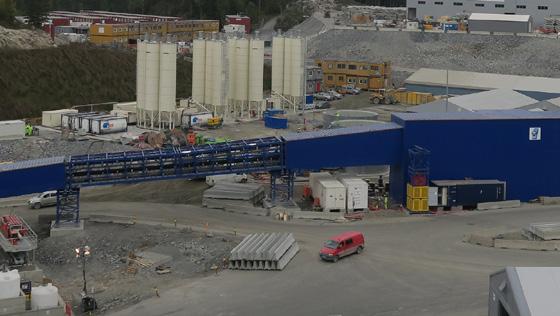
During depositing the spoil in the internal deposit area, dust was primarily managed by ensuring the moisture level of the spoil was sufficiently high to prevent dust generation from occurring. Dust binding chemicals and water spray was used on temporary transit roads as required.
The main internal roads were asphalted, and most of the production area surfaces were sealed. In addition, a chemical dust binder (magnesium chloride) was applied on internal roads to limit dust mobilisation by truck traffic. These measures ensured that dust generation was limited to a minimum.
Dust generation was a daily check list item in the environmental management plan, and environmental officers together with logistics department operators would respond quickly to any visible dust clouds arising.
A dust monitoring station was installed at the end of the deposit area, close to several neighbours. Dust samples were collected over the course of a month and analysed at an external laboratory. The results showed that emissions were generally low, and always far below the permissible level in the pollution permit for the project (“Tillatelse etter forurensningsloven for anleggsarbeider ved bygging av Follobanen mellom Oslo S og Ski stasjon”, Fylkesmannen i Oslo og Akershus, 2015).
Figure 8-2: Dust monitoring results.
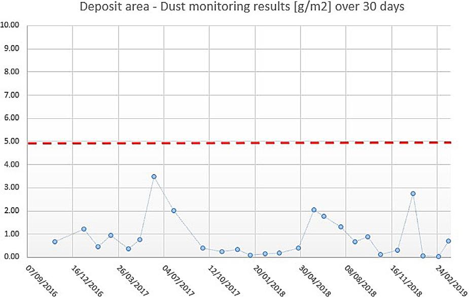
The project’s pollution permit stipulated that all tunnel water was to be treated and discharged to the municipal sewage network (Oslo VAV). The permit required continuous monitoring, flow proportional sampling, online monitoring access and weekly reporting of water quality parameters, such as pH, TSS, oil, nitrogen and heavy metals.
In order to both comply with these requirements, and to recirculate as much water as possible, the project established a large, advanced water treatment plant (WTP). Tunnel water from all 4 tunnels was collected in a detention basin in the caverns and pumped to the WTP outside the adit portals. The WTP consisted of buffer tank, decanter and filter press, pH control tanks, coalescence separator, quartz filters, and activated carbon filters. In addition, there were large industrial water storage tanks for treated water, and an emergency basin.
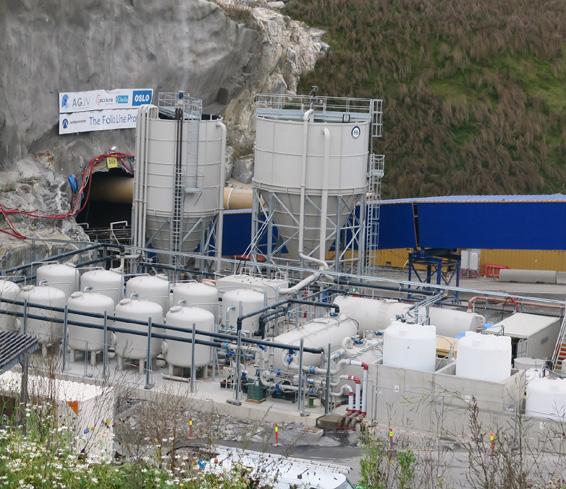
The WTP had a capacity of 60L/s (216m3/hr), and it treated water at incoming water quality of Total Suspended Solids (TSS) 10-20 000mg/l and pH 12-13, to clean water with TSS <20mg/l and pH 9. The WTP initially used hydrochloric and sulphuric acid for pH reduction, but in order to operate more efficiently, switched to CO2, which proved highly effective The WTP was operational 24/7 for the duration of the project, with a permanent fulltime operator.
Typically, in tunnel projects, the main water quality issues are related to pH and TSS. None of these parameters have caused problems in this project, because of the water treatment process.
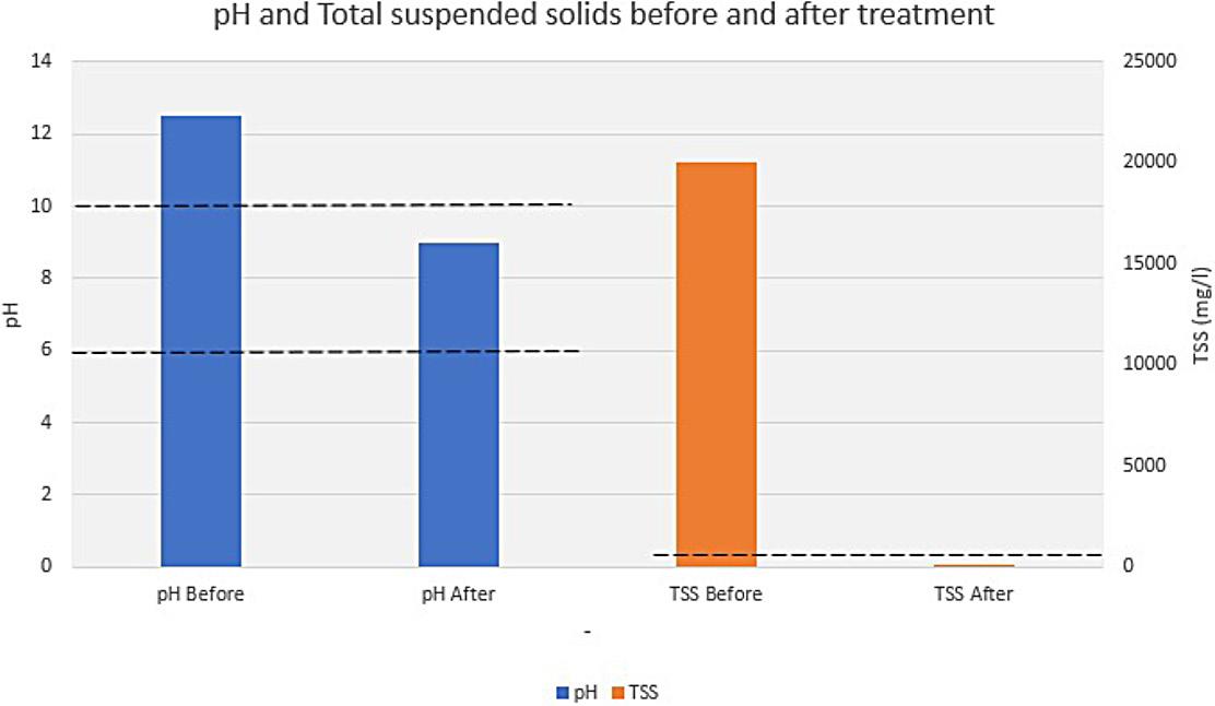
Furthermore, nitrogen, which is often one of the main contaminants of concern in tunnelling, has not been a problem in this project, mainly due to the use of TBM (compared to drill and blast).
However, the water treatment was not without challenges:
• Unbalanced incoming flow
- In the early stage of the TBM-drilling, there was limited balancing capacity for the raw water in the tunnel. This resulted in irregular flow into the WTP, which caused operational challenges such as overflows and clogging due to mud build-up in the decanter in the WTP. Overflows were collected in the internal containment system, but the this caused a very high workload for WTP operators.
- Two parallel detention basins and double pump sumps were built in adit north, which run on 12 hours rotation. Mud build-up in the basins was removed daily by an internal sucker truck and transported to the WTP on the surface.
- An additional filter press was built to support WTP1, which increased the capacity by 150% from September 2017.
• Treatment capacity
- To handle the total amount of water more than 60 l/s in the tunnel, the capacity of the water treatment plant had to be increased.
- A second water treatment plant (WTP2) was built in similar style to WTP1, with 30 l/s capacity. WTP2 was operational from May 2018. Combined capacity of WTP1+WTP2 was then 90 l/s
- While WTP2 was being built, contractor installed a temporary WTP in traditional style - using 6 sedimentation containers and acid pH adjustment, which was used to support WTP1 during periods of extraordinary high inflow from December 2017 to April 2018.
•
- Nearly 50% of the treated water from the WTP was sent to industrial water tanks for reuse in TBMs and on the surface. The remaining water was discharged to the municipal sewer system (VAV) under the environmental permits for the project. The VAV pipeline had a volume restriction of 25 l/s (later increased to 40 l/s) due to pipe size limitations downstream.
- This meant that the WTP operators had to restrict the discharge rate, and carefully balance the treated water to avoid exceeding the discharge capacity.
•
- The incoming water was highly basic, with pH in the range of 12-13
- Initially, pH was controlled with sulphuric acid. This increased sulphate concentrations and caused difficulties in complying with the discharge limit for sulphate.
- Then, the WTP switched to a combination of hydrochloric and sulphuric acid in order to limit sulphate concentrations. High consumption of hydrochloric acid, however, caused corrosion of WTP and uncomfortable working conditions.
- Finally, a CO2 system was installed for controlling pH. This worked efficiently without any significant drawbacks.
• Hexavalent chromium: Soon after start-up of the TBMs (TBM1 Queen Eufemia started up 05/09/2016, and by December 2016, all 4 TBMs were running), we observed a clear increase in chromium concentrations in the treated tunnel wastewater, from approximately 20 μg/l to 150 μg/l.
Figure 8-5: Chromium levels before and after start-up of the TBMs.
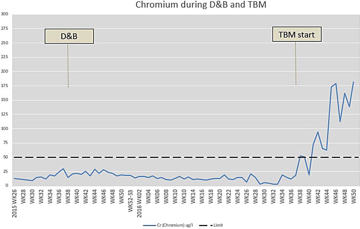
An extensive sampling program was implemented to determine the source of the chromium. It concluded that it originates from the various cement products used in the tunnel (mortar for segments, and pre-grouting), and from the concrete element production. As the water volume from the tunnel was significantly higher than from other sources into the
WTP, the cement use in the tunnel was considered as the main source.
Furthermore, it was found that nearly all the available chromium in the water was hexavalent chromium CrVI, as shown in the figure below.
Figure 8-6: Source sampling chromium.
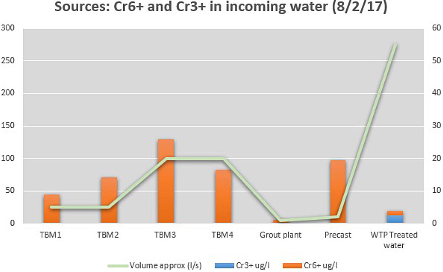
After a series of original research and development work, which included cooperation with consulting, industry and technology experts, AGJV developed several methods for reducing chromium concentrations in the wastewater. With the assistance of Acciona Aqua and Centre for Research and Innovation in Madrid, three alternative methods were tested in laboratory conditions: electrocoagulation, active carbon, and iron sulphate addition.
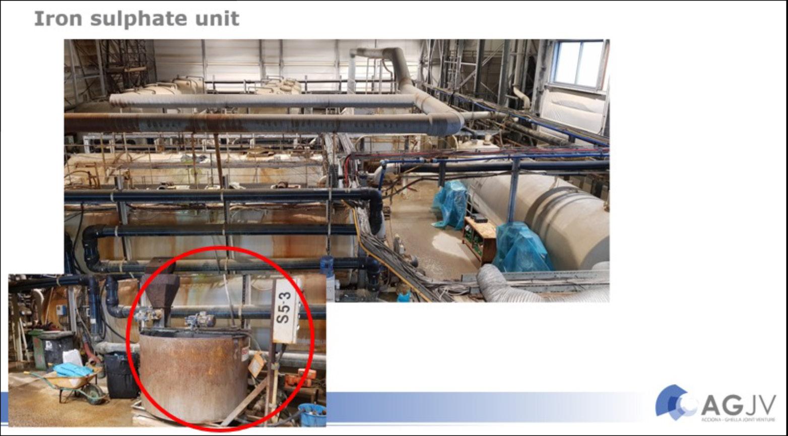
The chosen solution was robust enough to handle large variations in water quality and could be implemented in the current WTP without interfering with the 24/7 operation.
By adding iron sulphate heptahydrate FeSO4 7H2O, water soluble hexavalent chromium was reduced to trivalent chromium, and settled out together with the other particles in the wastewater.
Figure 8-7: Chemical formula for hexavalent chromium reduction in alkaline and acidic conditions.
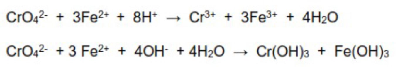
The method can be described as follows:
• Dosing tank and pump
• Mixing tank (1500 l), for mixing iron sulphate heptahydrate with clean water
• Addition of iron sulphate mix to wastewater decanter tank (40 m3), together with flocculating polymer, settling out 80-90% of the chromium
• The method is proven to work at pH 10-13, and should theoretically work in acidic conditions as well
• Dosing ratio dependent on water quality, approx. 0,1-0,3 kg/m3 wastewater
• Reaction-time <20 minutes
plant.
Compared to the total amount of solids, the amount of chromium was so low that it did not affect the contamination level of the dewatered sludge (filter cakes).
As shown in the below graph, which compares wastewater treated with and without FeSO4 treatment, the FeSO4 treatment achieved an 80% reduction.
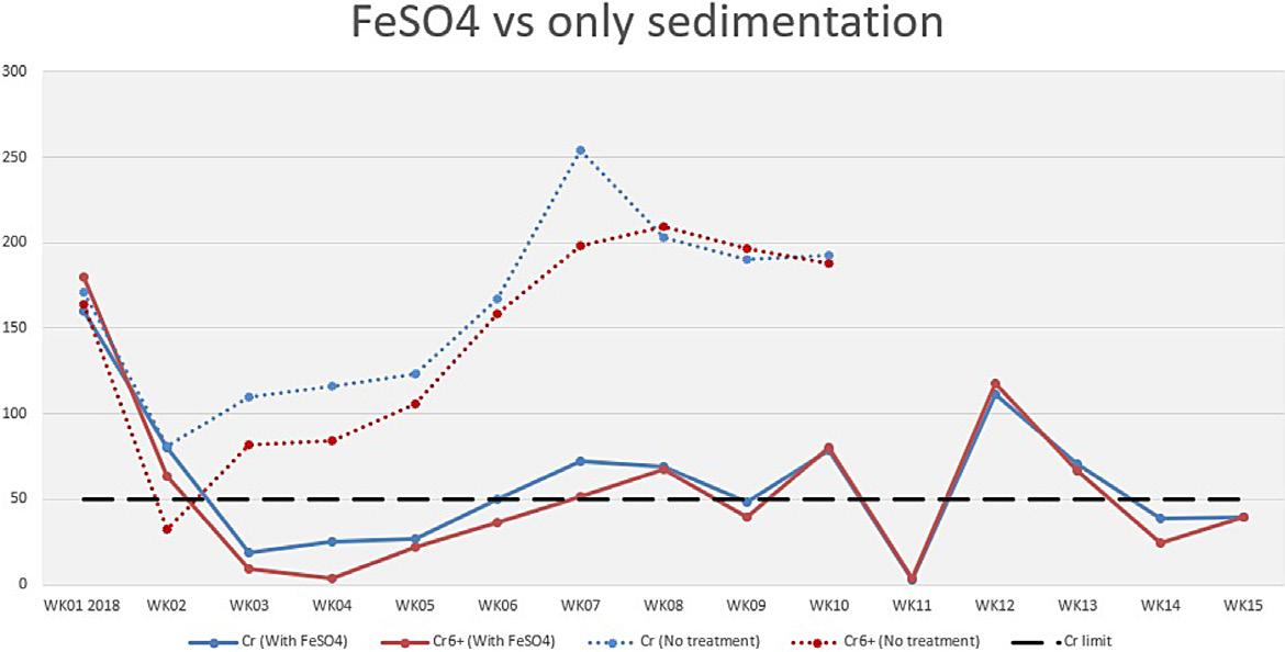
Chromium level in incoming wastewater varied over time, depending on groundwater intrusion in the tunnels, amounts of pre-grouting, and parallel work activities. There is no direct link to TBM as a driving
method. Cement works combined with high water flows lead to elevated chromium levels.
As with all water treatment systems, and any type of recipe, dedicated operators and continued attention is essential for optimal result. While the principles of water management remain the same; project, site, and personnel specific factors will have a significant impact on the success of any water management system. Thanks to the resources assigned to this issue and the dedicated project personnel, AGJV managed to resolve this issue successfully.
Figure 8-9: Comparison treatment with and without FeSO4
In total, 9 million tons of excavated material were brought out of the tunnel during the construction of the 20 km long twin tube tunnels, with 54 cross connections between the two tunnels. In addition,
several access tunnels, logistic tunnels and caverns were built for an efficient performance of the work. This is illustrated in figure 9-1 below.
From an early stage of the planning of the construction work, the project organization considered several alternatives for re-use of the excavation material. The spoil was defined as an important resource, and it was a goal for the project to find a sustainable solution for re-use of these 9 million tons of rock mass.
The project had access to a large rig area, called Åsland, centrally located approximately halfway between the two ends of the 20 km long tunnel section. Within the area which was originally approved by the municipality as a rig area for the performance of the tunnel, approximately 20% of the material could be re-used for building up the rig area and
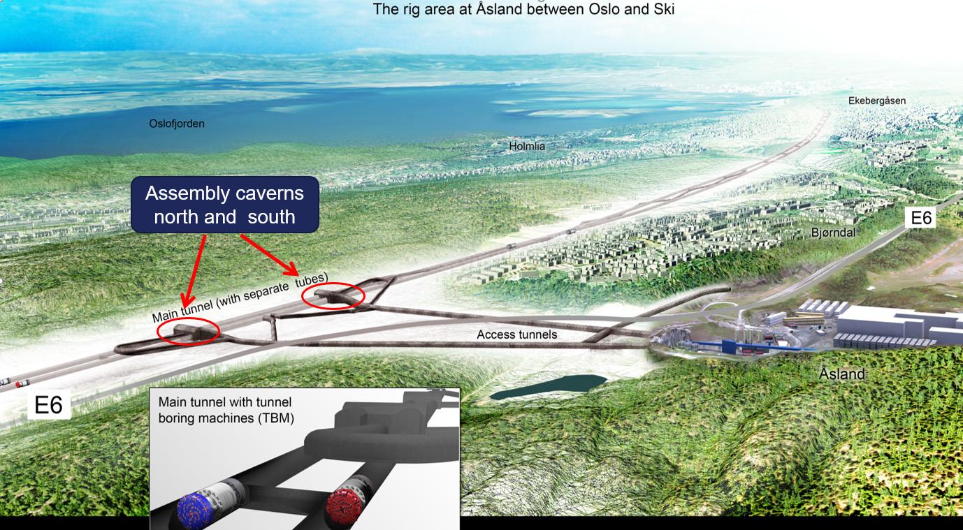
for re-establishing the terrain after the construction period. Most of this spoil would come from the excavation of access tunnels, logistic tunnels and caverns.
When it was decided to excavate the main part of the tunnel by four tunnel boring machines (TBMs), operating from this large rig area, it was also identified that production of segments for the tunnel lining could take place within Åsland rig area. This was described as an option in the tender documents. If the segments and the concrete should be produced within the rig area, it was also a requirement that 10 – 15% of the excavated material should be crushed into different fractions, which should be used as aggregates for the production of concrete.
To be able to prepare for an establishment of an efficient rig area, where all the main activities related to the tunnel excavation could be located, it was necessary to extend the rig area. Approval of access to an extended area linked to the area that was already approved, was done by an application described as new area development plan. An acceptance of this plan made it possible for the contractor to have all his activities related to the tunnel excavation within the rig-area, including three factory units for the production of the segments for the lining, storage area for the segments, facilities for handling the spoil, crushing the spoil, all kinds of workshops, offices for the contractor and the client, cantina and accommodation for approximately 470 workers. This is shown in figure 9-2.
In addition, it was also possible to prepare for a future residential and recreation area by re-using approximately 50% of the excavated material to fill up a valley linked to the rig area. This area development plan was not yet in place when the tender doc-
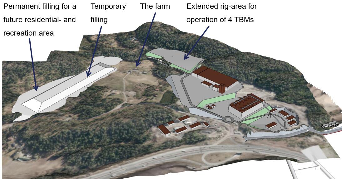
uments were sent out, but it was approved by the municipality before the contractors delivered their final bids, so during their preparation for their bids it was clear that approximately 50% of the spoil could be deposited within the rig area, as a basement for a future residential and recreation area.
In addition, the contractors had to search for other areas, outside the rig area, where filling was allowed. Bane NOR introduced one accepted alternative as a part of the tender documents and investigate various other locations, but the contractors were free to come up with other alternatives. The require-
ment from the client was that the alternatives were accepted by the municipality.
During the process of producing and achieving acceptance for the second area development plan, which allowed for re-use of approximately 50% of
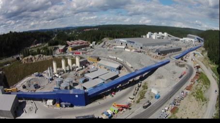
the spoil within the area, both Bane NOR and the Municipality of Oslo saw benefits for both parties and the value of sustainability for re-use of the material would be even higher, if all the spoil could be filled at Åsland. This plan is shown in figure 9-4 below.
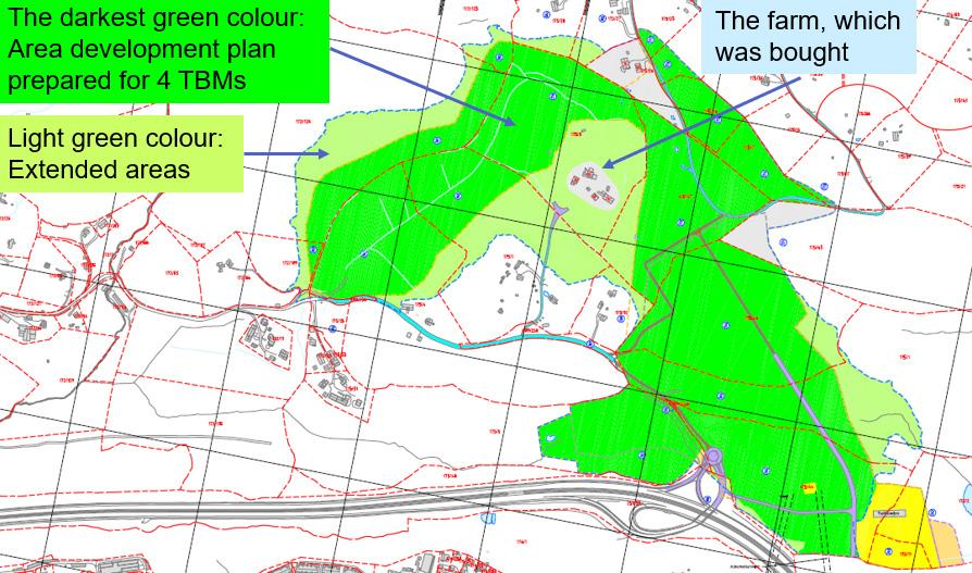
After acceptance of this plan, the project was finally allowed to fill all the spoil from the tunnel excavation within the area, as a basement for a future residential and recreation area. Re-use of short
travelled excavated material contributed to a massive reduction of traffic on the road system. All the material from the tunnel excavation was transported all the way from the four TBMs up to the edge of the deposit area by conveyor belts. Compared with an alternative of excavating the tunnel by drill and blast from seven different access-tunnels and transport all the spoil by trucks to the deposit area, a reduction of 27.000 tons of CO2 has been calculated for the TBM-alternative where all the spoil was transported out to the deposit area by conveyor belts.
The ground conditions in the valley, where most of the material was supposed to be deposited, consisted mainly of a thick layer of clay above the rock surface. Laboratory tests showed that the clay was very sensitive, recognised as quick clay, figure 9-5. This meant that disturbance of the clay structure, from digging, compaction or filling could within seconds transform the clay to a liquid soup. The clay basin was surrounded by solid rock on three sides. In the end of the valley, a retaining wall, like a dam, had to be established as a back-up. In case of a collapse of the clay during the filling, this wall would prevent the “soup” to float out of the valley.
To reduce the water content of the clay, a vertical drainage system was established as pre-work before the filling of excavated material could start. A grid of drainage pillars was carefully bored down into the clay, see figure 9-6 below. This vertical drainage pillars were connected to a horizontal layer of gravel to lead the water out to the edges of the valley. Before the actual filling of the deposit area with proper compaction could start, a preloading layer to reduce to impact of heavy construction machinery together with vibrating compaction was installed.
Figure 9-5: Geological profile along deposit area.
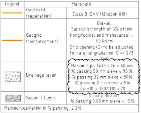
Figure 9-6: Establishment of a vertical drainage system (blue line illustrates the vertical drains installed in a pattern of 2mx2m).
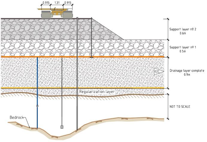
An exhaustive monitoring program consisting of settlement points, inclinometers and piezometers has been established at the deposit area, see figure 9-7. A maximum of more than 4m of settlements has been registered during the filling process. As illustrated in figure 9-8 were the settlements of the quick clay almost subsided after 2 years when the maximum filling height was reached. But the deepest quick clay deposit continues to settle for some centimetres per year. This also correspondences with the pore pressure development, figure 9-9. During the first period the clay was despite the vertical drains not able to drain in accordance with
the additional loading resulting in increased pore pressure. With a delay of several months the pressure finally started to reduce again and after approx. 2 years the pressure was back to the original level.
Bane NOR studied during autumn and winter 2019/2020 the surface settlements by InSAR. InSAR (Interferometric Synthetic Aperture Radar) is a technique that maps millimetre scale deformations of the earth’s surface with radar satellite measurements. The surface settlements were in the same magnitude as the quick clay settlements.
Figure 9-7: Monitoring of deposit area.
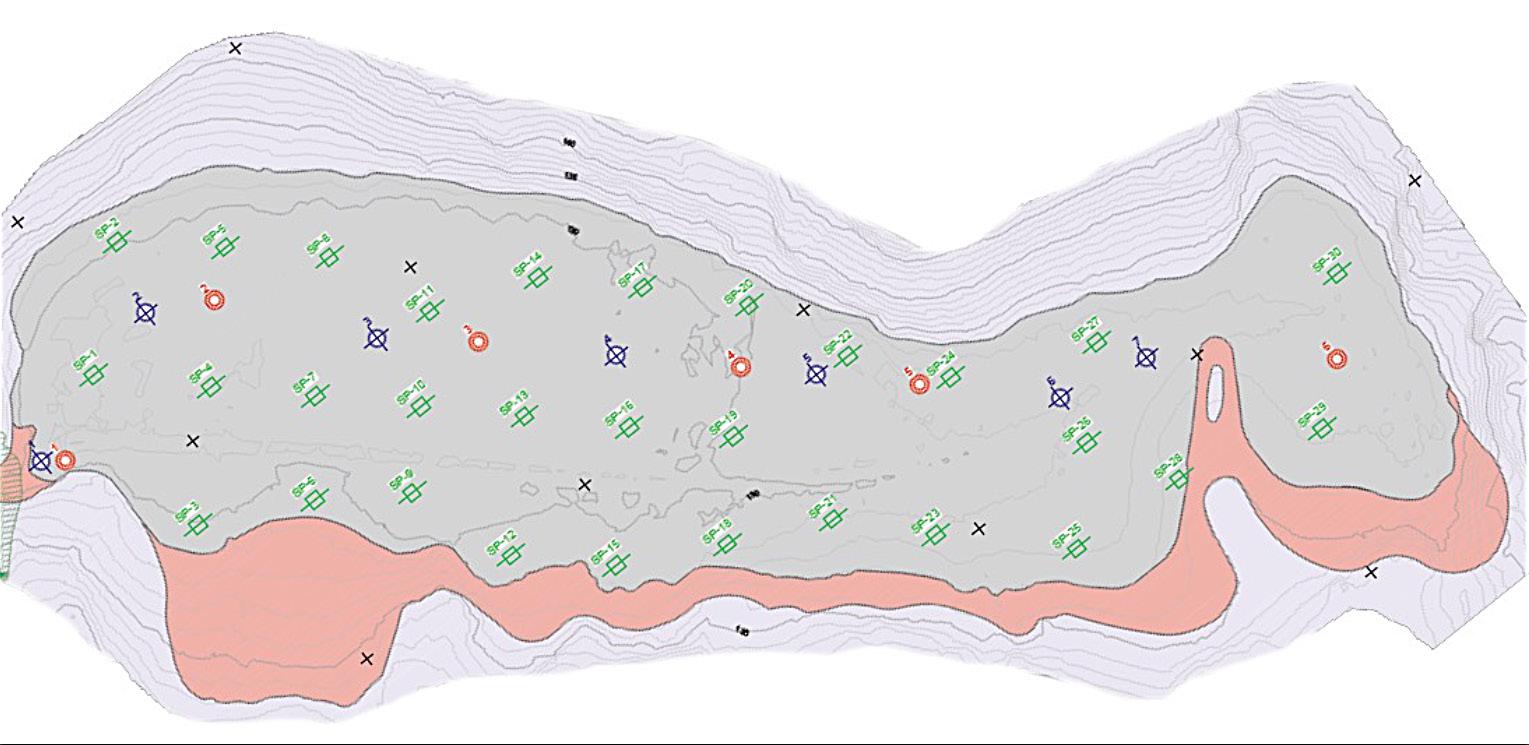
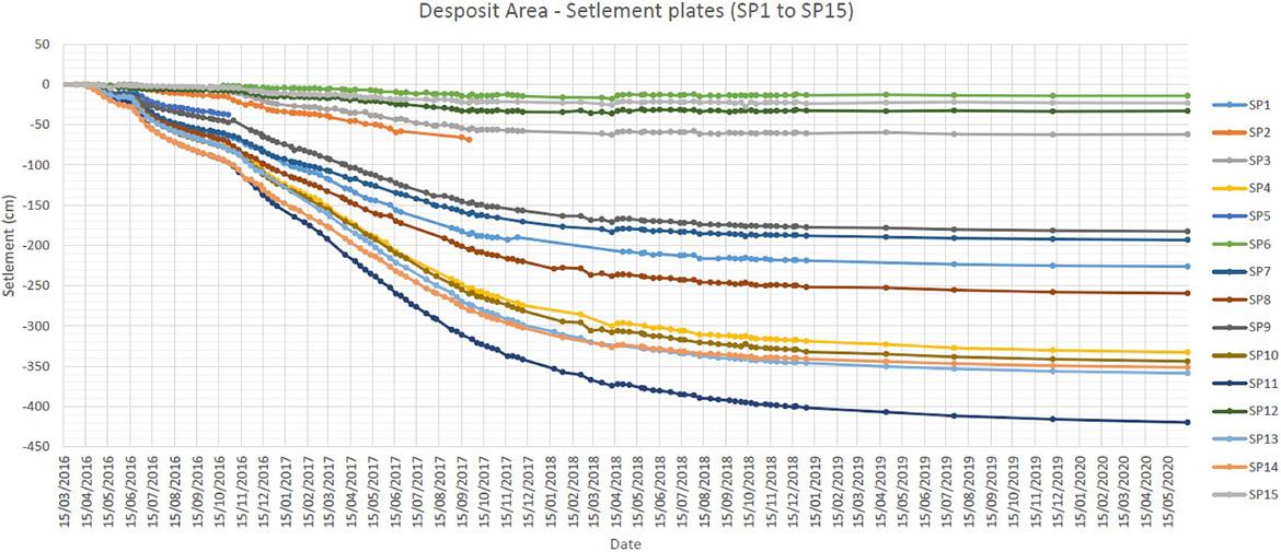
Figure 9-8: Settlements of quick clay.
Figure 9-9: Example of pore pressure development.
The spoil at the Follo Line consist mainly of hard rock as Precambrian gneisses, with variations between tonalitic to granitic gneiss and quartz-feldspathic gneiss. In the preparation of the tender documents Bane NOR made a study of spoil properties from older TBM-tunnelling projects in Norway. The report, which summarized the data from tunnels for hydropower plants performed in the 1970- and 1980-ies, highlighted the issues to expect from the spoil from the Follo Line (NGI, 2016).
• The large volume of fines in the spoil
• The shape of the particles, which is characterized as flaggy, due to the disc cutters on the TBM
• Brittle particles with low crushing resistance
• Sensitivity to variations in water content
Despite this, laboratory test on the material in the study showed that the geotechnical properties of the spoil were good (Statkraft,1986). It was known
from the study and recommended in the tender documents that the spoil should be handled and placed with care, to avoid high porosity and settlements in the fill.
The contractors joint venture consisting of Spanish Acciona and Italian Ghella (AGJV) have performed extensive field and laboratory testing to assure and document the quality of the TBM-spoil fill (AGJV, 2019).
The work with the fill of TBM spoil started with trial fills. In the trial fills, four different thicknesses of the layers were tested, combined with varying amount of compaction work. The aim was to find the optimum thickness of the layers and suitable compaction effort, that would be valid for the whole fill.
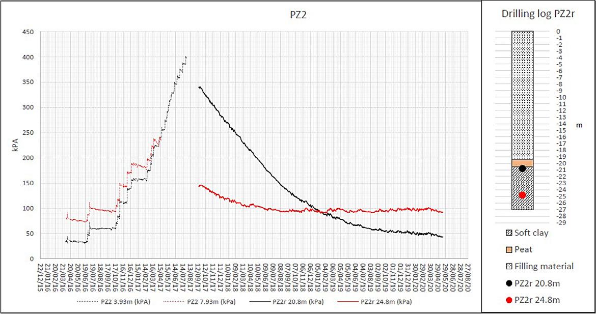
The test was conducted on four different thicknesses of layers: 0,5m, 0,7m, 1,0m and 1,5m as seen in figure 9-10.
Figure 9-10: Longitudinal section along the trial fill showing the different sections and layer thickness.
The trial fill took place late in the autumn 2016 after and under heavy rainfall. Initially the test results were confusing. The plate load tests (PLT) indicated that the deformations in the fill was to large, but testing with nuclear density gauge (Troxler) compared with results from Standard Proctor laboratory tests, and later, the test pits in the trial fill, demonstrated that the density of the fill and the compaction effort was sufficient for layer thicknesses of 0,7 m. The number of passes was six with a vibratory roller of 25 tons. The trial fills showed a homogenous grain size distribution in the material. The average water content was between 5 – 8 %, and the material was characterised to be sensitive to increase the water content.
One of the challenges with TBM spoil from large projects, is the amount of materials to be handled continuously. The Follo Line had four tunnel boring machines operating simultaneously. The transport of masses could not stop or be delayed, else the spoil would pile up very quickly in the spoil shed and probably force a stop in the whole TBM production line. An important decision based on the trial fill was, that the fill work should only be performed when there was little or no precipitation. When the weather forecast predicted rain, the spoil was transported to other deposit sites outside the building platform area. This also secured the working conditions on the fill and the quality of the fill.
Another important mitigation in order to protect the TBM spoil from more water, was transporting the spoil out on conveyor belts under a cover. On the other hand, it was a need to add water on the TBM to avoid too much dust in the tunnel. The material was stored in the spoil shed for a short draining.
Requirements set for compaction control state that measured dry density must be within 95% of the proctor compaction test results. The plate load test results were according to contract required to achieve E1 > 20MPa, and E2/E1 ≤ 3.
The contractor worked out a test procedure for every layer in the fill, which consisted of:
• 2 tests of natural water content (lab)
• 2 grain distribution curves (lab)
• 2 tests where the optimal water content for compaction and maximum dry density were determined using the Standard Proctor test (lab)
• Several tests for each layer of the deposit with Troxler - nuclear density gauge (field)
• 2 plate load tests (field)
• Number of passages or weight of compaction equipment
The natural water content in the TBM-spoil TBM spoil is sensitive to water, and variation in water content causes variations in geotechnical performance under and after compaction of the material. Natural moisture of the spoil was measured in the laboratory on the same samples as grain distribution tests. The average value for the water content in the fill was 5.7 – 5,8 %. The maximum water content was approximately 8.7 to 9 % and minimum between 0.27 and 2.85% (AGJV, 2019).
Grain size distribution testing was performed to control the variation in the materials during the earthworks. In the master thesis from Marianne Dahl (Dahl, 2018), the grain size distribution curves from more than 25 layers are plotted and presented as shown in figure 9-11. The TBM-spoil from the Follo Line project is relatively homogenous and is characterized as a well-graded, sandy, silty gravel. The spoil from contents of 40-95% gravel (> 2 mm), and 10-18% fines (<0,063 mm silt and clay). The well-graded materials achieve a good compaction and high density. In well-graded materials, a larger proportion of the pores are filled with smaller grains and the density increases. Masses with a low porosity are usually stiffer and have a higher modulus than masses with more voids. The high content of gravel contributes to high shear strength and low compressibility (Statkraft,1986).
The high content of fines (<0,063 mm) of 10-18% do not satisfy the requirement to self-draining materials.
9-11:
The Standard Proctor compaction tests are performed on material taken from the spoil shed together with materials for water content. Two samples are taken for each layer of the deposit. The result of the Standard Proctor test is that the average dry optimum density is about 2.15 t/m3 and the corresponding optimum water content is approximately 8 %. The water optimum is slightly higher than the average natural water content on 5,7 %.
In figure 9-12 two proctor curves from the tests on Layer nr. 11 is presented in colored lines.
When applying a correction of the maximum dry density with respect to grain size it should be possible to achieve an average dry density of 2.2 t/m3 with this material.
It has been conducted several measurements with nuclear density gauge on each layer of the fill. The results will always vary with the density of the rock mass, water content and how tight the test rod is in contact with the soil.
The main results from AGJV on the Troxler tests are summarized below (AGJV, 2019), also showed in figure 9-12:
• Density from the Troxler test is usually higher that the maximum determined by the Proctor tests (>100 % Standard Proctor).
• Moisture by the Troxler measurements is below the optimum determined by the Proctor tests and usually in the range of natural values of water content.
In figure 9-12 the Troxler data from layer 11 is presented together with the according Proctor curves (NGI, 2018).
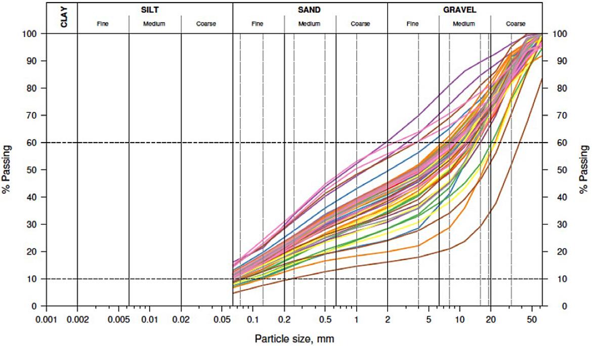
The plate load test (PLT) is frequently used as a tool in compaction control in road constructions. Plate load tests were performed after compaction of each layer to determine the achieved stiffness of the first loading cycle E1. Furthermore, by applying the load twice with complete release of pressure between the two cycles, it is possible to evaluate the degree of compaction, E2/E1.
The results from the plate load test showed a less stiff material than expected, and many of the plate load test did not satisfy the requirements. On average there is obtained a deformation moduli EV1 = 26.5 MPa and a ratio EV2 / EV1 at 3.43 (Dahl, 2018).
Layer 11 presented in figure 9-12 is the results from a layer where the plate load test was not accepted,
Figure 9-12: Combined plot of data from Troxler measurements and two laboratory test Standard Proctor on Layer 11. The Troxler data shows better values of dry density than the Proctor curves, and the ratio of air-filled voids is 5 –7%. The field data are better than the requirements.
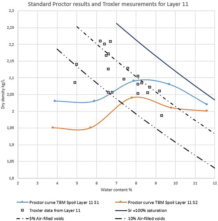
while the Troxler data are better than the reference Standard proctor test. Random tests on several layers with poor results from PLT shows the same (NGI, 2018).
Under the compaction work it was reported several times that the surface was soft and wet, and that the number of passes with the rollers was not achieved until some days after the first attempt. When conducting plate loading tests, the requirement for uniformity of the surface is important. Attempts have also been made for plate load tests with and without alignment with plaster or sand (Barnard and Heymann, 2015). In short, the authors conclude the experiments that the use of plaster or sand gives an increased value at the first time deflection E1, up to 50%. These two factors in combination might be the cause of the poor result of the plate load tests on the fill.
To investigate whether the compaction of the fill was acceptable despite the results from the plate load test, additional test pits and permeability tests were
undertaken to evaluate the actual achieved dry density against the standard Proctor maximum. During the tests the permeability was also measured, and the drainage properties of the fill were evaluated.
The four test pits presented of Dahl (Dahl, 2018) show high values for dry density, see figure 9-13. The comparing of test pit and control measurements with Troxler tests conducted on the surface where test pits were performed, show good correlation for test pit 1, 2, 3 and 4 (NGI, 2018).
The interpretation of the results from the test pits indicate that compaction of each layer is better than the plate loading tests indicate alone. All measurements with Troxler on the surface of the pit before excavation are above 95% Standard Proctor and with an air-filled pore volume of 7 % or less.
The results from the Troxler tests and test pits are plotted in a compaction plot, together with results from Standard Proctor tests, se figure 9-13. The figure shows that the quality of the compacted fill
is better than the requirements of 95 % Standard Proctor. The average maximum dry densities from the Proctor tests are plotted as 100 % standard Proctor, with a purple curve. The curves from the Standard Proctor test are sensitive to the solid density of the particles, ρs, and is probably the reason for some of the Proctor curves plotting on the high side, above the line for 100 % saturation Sr=100 %.
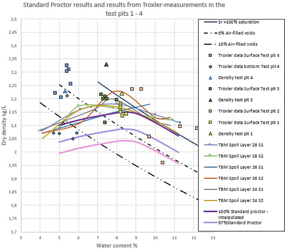
The standard Proctor tests indicate an average maximum dry density of ρd=2.15 t/m3. This indicates a dense and stiff fill. The optimum water content lays
between 8 and 9 %. This must be considered satisfactory, given the variations in volume of fines and water content.
The installed monitoring system indicate that the consolidation of the quick clay deposit is flattening out, but some settlements in the range of a few centimetres can still be expected. The comparison with the surface settlements evaluated by InSar show the same magnitude of settlements, which means the filling as such does almost not have any settlements, which is another indication of a high quality filling.
Figure 9-13: All measurements with Troxler on the four test pits, plotted together with the archived Proctor curves for the nearby layers. Most of the measurements are above 95 % (pink line) Standard Proctor and with an air filled pore volume of 7 % or less, which must be considered satisfactory for the quality of the fill.
Before the tender documents were produced, the properties of the rock mass were analysed and found acceptable for re-use as aggregates for concrete production. Based on this, crushing and reuse of approximately 10 – 15 % of the material was implemented as a requirement in the contract.
The production of the segments started up during the summer of 2016, approximately 3 months before the first TBM started the excavation. This part of the production was based on delivery of commercial aggregates from an external quarry.
When the TBM production started in the autumn of 2016, testing of the quality and achievement of the different fractions as well as the chemical components of the crushed material were performed.
The material was crushed into the following fractions:
• 0 – 8 mm (sand)
• 8 – 11 mm (fine gravel)
• 11 – 22 mm (course gravel)
The crushed material was washed before it was transported more or less directly into the concrete production line. The aggregates were dropped from the top in the spoil shed. The water in the material were drained downwards towards the hatch in the floor, where the material was dropped on a conveyor belt and transported to the batching plant, only 1 – 2 days after the crushing. For the sandy material (0 – 8 mm), the time for the water to be drained out was too short. Much of the water remained in the material and caused a high humidity of this fraction. It was measured up to 17 % humidity, while the recommended value is 3 – 7 %. It was known that a high and unstable water-content in the aggregates would affect the production and quality for the concrete. This challenge related to the high water-content was not a problem for the two gravel-fractions. After washing, the water drained more efficient through the material for these fractions.
In accordance with the contract, the concrete production should comply with the standard NS-EN-206. According to this standard, the quality of aggregates in the concrete should comply with the standard NS-EN-12620+NA. The standard requires two steps of testing; first initial testing to declare the properties of the aggregate material. Then frequent production testing must be performed to check if the properties of the material changes compared to the initial results. The standard requires a certain number
of tests to be performed before the aggregates can be used for concrete production.
Pyrrhotite and accepted content of Sulphur In November 2016, shortly after the testing had started, chemical analyses of the aggregates identified presence of the unstable mineral pyrrhotite, Fe1-xS. This is, as Pyrite, FeS2, an oxidizable iron sulphide. These minerals react with water and oxygen and form iron oxyhydroxides and sulphuric acid. In concrete, sulphuric acid will then react with the phases of the cement paste and form gypsum and ettringite, which will cause expansion and cracking of the concrete. Pyrrhotite is more unstable than pyrite, and in the presence of water and oxygen, this mineral reacts relatively quickly.
NS-EN-12620+NA requires testing of sulphur content and presence of unstable minerals as pyrrhotite as a part of the initial testing. During production, total sulphur content shall be tested at least once a year. The standard states the following regarding the total amount of sulphur:
The total content of sulphur in aggregates and filers shall not exceed 1 mass percent S. Special precautions are necessary if it is pyrrhotite in aggregate. If it is known that this mineral is present in the aggregate, the total sulphur content shall not exceed 0.1 % S.
In Norway, this limit for total amount of sulphur is defined as 0.1 % when pyrrhotite is present. This means that a total amount of sulphur accepted may be 0.144 %. Some other countries, Canada for example, has defined the limit to be 0.10 %. Many, within the concrete industry in Norway, argue to use the conservative limit 0.10 % instead of 0.1 %, as stated in the standard. In Ireland, for instance, an amount of sulphur up to 0.3 % is acceptable without any further testing of the petrographic condition. However, worldwide it seems to be limited experience regarding the amount of sulphur that can be accepted if pyrrhotite is present to avoid damage of concrete. More scientific investigation should be done within this field.
For identification of the total amount of sulphur, a method described in the standard NS-EN-1744-1 was used. Further, the identification of sulphide minerals was performed by using the test method known as DTA (Differential Thermal Analyses). Through the method, presence of both pyrite and/or pyrrhotite is identified, but it is not possible to determine the amount of these minerals by using DTA. Thus, NS-EN-12620+NA does not state any maximum limit for the content of pyrrhotite if this is present.
Along the tunnel the rock consists mainly of three groups of pre-Cambrian gneisses: Tonalitic to granitic gneiss, quartz – felspathic gneiss and biotitic-augen gneiss. The mechanical properties of these gneisses are similar, but the variations are related to the amount of quartz, feldspat and biotite. Gneiss is a foliated metamorphic rock. As a result of several occasions of foliations, the coarse mineral grains have been arranged as a banded structure. Several generations of intrusions occur, some of them still with the character of a diabase, mainly of pegmatite, and some have been transformed to amphibolite and folded into the gneisses. The amphibolite and pegmatite appear as elements within the gneisses with varying shape and thickness in alternating sequences. The different rock types cannot be related to specific sections of the tunnel, and the entire gneiss formation is defined as one geological unit for the entire tunnel section. In the northern part of the tunnel, the frequencies of fracture zones, which intersect the tunnel is less than in the southern part of the tunnel. In theory, both pyrite and pyrrhotite may occur within fracture zones. Pyrite was, as a part of the pre-construction investigation, identified in cores including such fracture zones. Pyrrhotite may also occur as a common trace constituent of mafic igneous rocks. In addition, it can also occur in pegmatites and in contact metamorphic zones. Pyrrhotite is also a known mineral in amphibolite, gabbro, and marble.
Initially, pyrrhotite had not been identified during the pre-construction testing of cores along the tunnel. It was identified for the first time when the contractor performed his initial testing for declaration of the material before he could use it as aggregates for the concrete production for the segments.
In total, 30 samples from produced aggregates, from TBM spoil material and from cores from initial geological investigations were analysed for content of sulphur and presence of pyrrhotite. The results can be seen in table 9-1 below.
As a summary, we see that:
• It was identified pyrrhotite in 18 of 30 samples (60 %)
• 6 of 30 samples, 20 %, had a total content of S > 0.1 % in combination with presence of pyrrhotite, and did not fulfil the requirements in NS-EN-12620+NA
• 4 of the 30 samples had a total content of 0,10 % < S < 0.15 % in combination with presence of pyrrhotite
By comparing the presence of pyrrhotite with the geological conditions, it was difficult to find a clear correlation. This is shown in figure 9-14 below. It was only the pure samples of amphibolite where no pyrrhotite were identified, but the number of samples is too low to conclude that pyrrhotite never occur in the amphibolite present in this area. As known by experience, pyrrhotite is generally a common mineral present in amphibolite. However, amphibolite is only present in small amounts within the rock mass, and mainly as lenses and banding within the gneisses.
Even though the occurrence of pyrrhotite may correlate to the degree of fractures in the rock mass, it was also difficult to see a clear correlation of this when the result of samples taken from the different parts of the tunnel were compared. See the results in figure 9-15 below.
Maybe it is a weak tendency of a higher frequency of pyrrhotite in samples from the southern part of the tunnel section, where the frequency of fractures and water on fractures were higher than in the north. However, pyrrhotite was present in the northern section as well, and the picture of where this mineral could be expected to occur, or not, was too unclear to define areas where it would be safe to excavate for aggregate production.
Pyrrhotite in aggregates is not known as a huge problem in Norway. The main source for production of aggregates is post-glacial fluvial deposits of natural sand and gravel. This material has been exposed to oxidation through thousands of years. Pyrrhotite, known as an unstable mineral, when it is exposed to oxygen and water, is therefore more or less eliminated.
Excavated material from tunnels has not been exposed to oxidation. The likelihood of having pyrrhotite present in aggregates produced from this spoil is therefore higher than if the aggregates is produced form material which has been exposed to oxidation over a long period. In our case, where the material was supposed to be crushed immediately after excavation, and then go directly into the concrete production, it was not time for testing, and pyrrhotite-free aggregates could not be guaranteed.
As a result of the testing of whether pyrrhotite were present in different areas along the tunnel section or not, and the measurements of the total content of sulphur in the samples, Bane NOR found the risk
Table 9-1: Test results where presence of pyrrhotite and total amount of sulphur is measured.
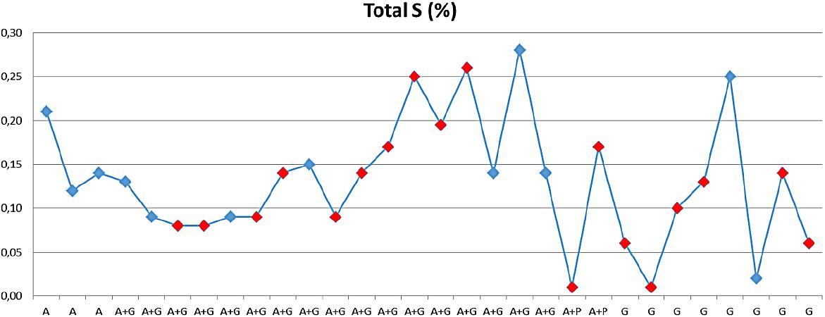
Figure 9-14: Pyrrhotite found in different geological compositions marked as red dots. A=Amphibolite, G=Gneiss and P=Pegmatite.
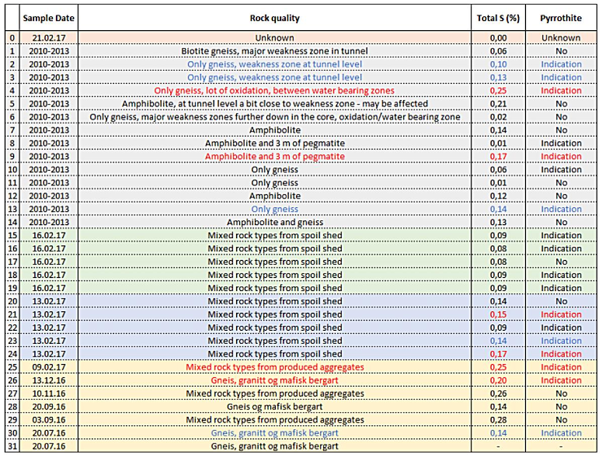
Figure 9-15: Pyrrhotite found in different samples marked as red dots. N represent samples taken from the northern part of the tunnel section, between Åsland and Oslo. S represent samples taken from the southern part of the tunnel section, between Åsland and Ski.
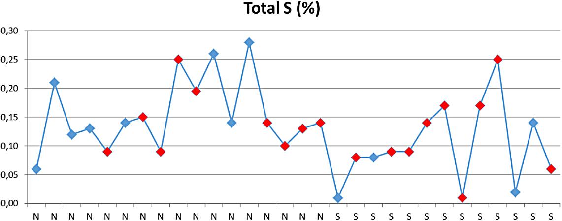
of using aggregates which would have made damages to the concrete in the segments unacceptable. Due to limited areas for storage of aggregates and short time from production of the aggregates until they went into the production, it was not possible to identify pyrrhotite-free aggregates or clarify spoil for aggregate production in due time.
Since approximately 20 % of the tested samples were outside the recommended limits for aggregate production, neither contractor nor client wanted to take the risk by using spoil from the tunnel excavation for production of aggregates. The parties agreed to buy commercial aggregates for the concrete production instead.
The production line for the concrete production was originally, in accordance with the contract, set-up for re-use of spoil from the tunnel excavation, as aggregates.
It has often been stated that spoil from TBM excavation has no value compared to excavated material from drill and blast production. However, the way the material, nearly 9 million tons, is handled and filled in accordance with a specific procedure, has demonstrated the opposite. At the Follo Line project re-use of short-travelled TBM excavated material has been performed to build up a quality basement for a future residential area.
The transportation of the material by conveyor belts, all the way from the four TBMs up to the surface, and the re-use of the spoil within the extended rig area, has reduced the discharge of CO2 by 27.000 tons,
compared with the alternative of excavating the tunnel by drill and blast from seven different access points and transportation of all the spoil by trucks to the deposit area.
Re-use of the spoil for aggregate production would have contributed to an even higher degree of utilizing the material and reduction of transport on the road system. The production was planned for crushing of 10 – 15 % of the material to aggregates. Instead, the local produced aggregates had to be replaced by commercial aggregates from an external producer.
Higher focus on testing of petrographic properties and content of different minerals, which may affect the quality of concrete, should have been prioritized at an earlier stage. An early identification of the presence of pyrrhotite would have limited the uncertainty related to aggregates and contributed to a tailor-made production line based on delivery of commercial aggregates from day one.
To be able to deal with unfavourable spoil for the concrete production a sufficient big area for intermediate storage, sorting and handling of spoil would be required, which the Follo Line project did not have available.
The presence of quick clay at the deposit area did, thanks to the applied mitigation measures of the vertical drains with drainage layers and preloading before the quality filling started, not result in any collapse of the quick clay. The consolidation of the quick clay could be accelerated and was by the end of the TBM excavation almost finished.
Acciona & Ghella (AGJV) (2019)
UFB-31-A-67013 00E “Project: The Follo Line project, EPC TBM. Follobanen, Åsland. Spoil Area”. Final Report.
Barnard and Heymann (2015)
“The effect of bedding errors on the accuracy of plate load tests”. J. S. Afr. Inst. Civ. Eng. vol.57 n.1 Midrand Jan./ Mar. 2015
Dahl, Marianne. (2018) “Investigation of geotechnical properties of TBMspoil from the Follo Line project”. Master- degree thesis for Marianne Dahl. NTNU 2018.
NGI (2016)
Report UFB-30-A-70072. “Application of TBM spoil as a quality fill for Gjersrud/ Stensrud township. Follobanen». Bane NOR.
NGI (2018) Report 20180498-01-R. «Kontrolldata fra fylling av borkaks fra Follobanetunnelen. Evaluering av geoteknisk kontroll av fylling av borkaks».
Bane NOR (2020) Report UFB-31-A-70105 00B. «Deponiområdet Gjersrud – Stensrud. Vurdering av kvalitet av utført fylling ved Gjersrud – Stensrud»
Norwegian Standard NS-EN 12620+NA: «Aggregates for concrete»
Silje Gystad Ytterdal, Elisabeth Grasbakken, Berit G. Petersen. 29.05.2017. “Memo- Evaluation of risk regarding pyrrhotite in aggregates.” Bane NOR, Oslo, Norway.
Statkraft (1986). «Prosjekt fullprofilmasser. Materialegenskaper». NGI report 85607-1. 30. may 1986.
There are quite a few examples of TBM projects that have suffered low progress and high cost due to improper design of TBM and cutters. Dealing with massive, homogeneous, abrasive, and extreme hard rock with UCS in the range of 100-300 MPa, would demand a specific design of the TBMs and the cutters. This chapter will focus on design parameters that had to be considered in specifying the TBMs for hard and massive rock conditions. This included design of cutters, cutterhead, main bearing assembly and the rest of the TBM system as well. Based upon geological investigations and extensive testing of rock samples, the Project owner set strict requirements to the TBM design already in the invitation to tender.
TBM tunnelling in hard rock conditions is associated with high risk related to advance rate and cutter consumption, and TBM design based on expected rock mass properties is a crucial part of the front-
end risk management in such projects. In order to cope with extreme hard rock challenges anticipated on the Follo Line project, a robust TBM design was imperative. The general thinking should be that the geological pre-investigations cannot reveal the complete picture of the rock mass properties, hence, TBM design should at least match the expected geological conditions.
The general understanding of rock breaking under a disc cutter is shown in figure 10-1.
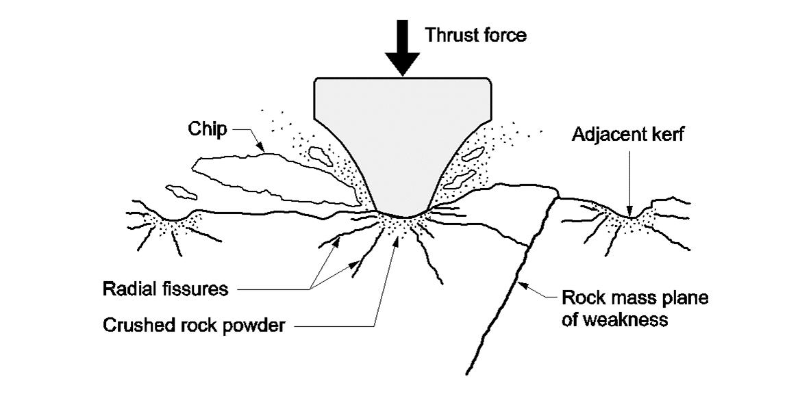
During rock breaking under a disc cutter, efficiency is characterized by the size and shape of the largest chips, and by the amount of fines produced. For a given rock mass, rock-breaking efficiency may be increased by increasing the applied cutter thrust force (i.e., the contact stress under the cutter ring) and/or increasing the number of cutters on the cutterhead (i.e., decreasing the average cutter spacing).
10-1: Rock breaking under a disc cutter (Bruland 1998).
Efficient boring in extremely hard rock conditions is characterized by very high average cutter forces, cutter peak forces, cutterhead vibration levels and cutter ring wear. The TBM design should be based on these experiences.
Based on field data from more than 250 km of hard rock tunnels, the NTNU, Norwegian University of Science and Technology, has derived some important design principles for hard rock TBMs (Bruland 1998) that were implemented in TBM design for the Follo Line project.
For individual disc cutters, the very high average and peak cutter forces have a strong impact on the design. The trend has been to increase the cutter bearing size and the cutter ring diameter in order to apply higher cutter thrust. Since 1985, standard cutter diameter for hard rock conditions has been 19in, with 20in being the possible next step.
The design of the cutter ring itself relies very much on the current steel material technology. A constant cross section type is used, with cutter ring edge width varying from 15mm to 25mm. The necessary edge width is generally larger in the outer part of the cutterhead than in the inner part. A cutter in the outer part of a cutterhead will have higher rolling velocity and is exposed to higher peak loads than a cutter in the inner part of the cutterhead. Hence, a wider ring is needed to avoid destructive wear in these outer positions.
The number and layout pattern of the disc cutters on the cutterhead plays an important role in hard rock conditions. Figure 10-1 indicates that the spacing between adjacent cutter tracks influences the necessary thrust to break large chips - the larger the spacing, the higher the necessary thrust. The second fact to consider, is that the rock breaking work increases with the square of the radius from the centre of the tunnel face and outwards. Hence, spacing between cutter tracks must decrease towards the gauge.
When considering rock breaking efficiency and cutter wear only, the ideal cutter layout pattern would be to place all cutters along one diameter line of the cutterhead, for example, with cutters in tracks one, three, five etc. on the left-hand radius and cutters in tracks two, four, six etc. on the right-hand radius. However, such a design would generate extremely high and unbalanced forces on the cutterhead structure and on the main bearing. The seemingly best alternative is to apply the same alternating cutter placement along the two arms of a double spiral starting in the cutterhead centre.
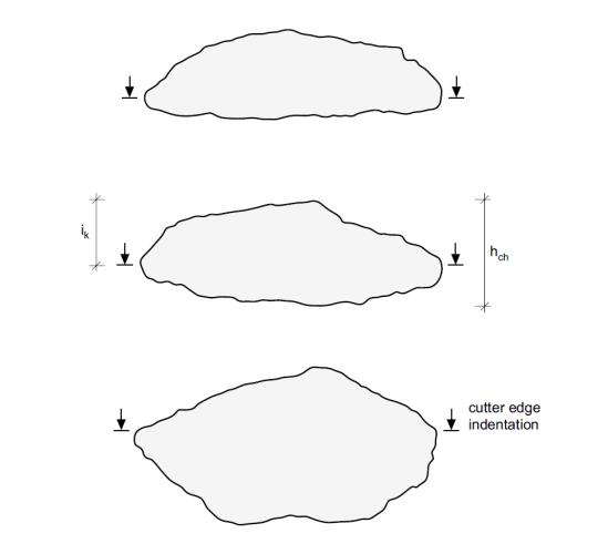
Figure 10-2: Cross sections of chips collected during a penetration test. Increasing rock breaking efficiency from upper to lower chip.
The general experience is that the total number of cutters on a cutterhead intended for boring in extremely hard rock conditions, should correspond to an average cutter spacing of approximately 70 mm over the cutterhead. When extremely hard rock conditions are expected, one must consider having more cutters on the cutterhead in exchange for smaller openings for muck removal.
Due to very high average and peak cutter forces, the main bearing will have to respond to a very high and unbalanced load situation. Considering the total rock-breaking work of the tunnel face, half of the work will be outside 0.7 of the cutterhead radius. Also, the cutter peak loads will increase towards the gauge due to the higher rolling velocity of the cutters and the curvature of the cutterhead structure. Hence, the main bearing diameter should be in the range of 0.7 of the cutterhead diameter.
Efficient boring in hard rock conditions is associated with strong vibrations originating from the high peak loads of the rock breaking process itself. These vibrations will put large strain to the cutterhead structure in general and on the cutter housings in particular. The simple solution is to add structural strength and weight to the cutterhead using steel.
One more item to consider is the stiffness of the cutterhead structure and the cutterhead thrust system. The stiffness of the cutterhead structure will be improved by more steel in the cutterhead structure. The recommendation for the thrust system is to increase the hydraulic stiffness by increasing the
Figure 10-3: Normal force recorded during linear cutting tests. Except from the hydraulic stiffness, cutting parameters are identical (Snowdon et al., 1983).
diameter of the thrust cylinders and/or increasing the number of thrust cylinders.
From studies carried out, the rocks along the tunnel alignment consist of Precambrian gneisses with bands and lenses of amphibolite and pegmatite with several intrusions. The rock mass is quite homogenous and competent with moderate jointing. The demanding massive, hard, tough, and abrasive rocks have a UCS in the range of 100MPa to 300MPa. This is described in more detail in Chapter 3 “Preconstruction planning and geological conditions” The expected advance rate according to the NTNU Prediction model (Bruland, 1998) was 15.6m per day.
The Follo Line project, developed by Bane NOR under commission from the Ministry of Transport and Communications, is a pilot project for a new contract model as well as new tunnel excavation methods for Norwegian railway tunnels. The use of EPC contracts, the use of drill and blast in combination with drill & split and the use of TBMs pave the way for innovation and knowledge upgrading. The project construction includes five separate EPC contracts and one contract for the signal system of which the EPC TBM contract is the largest.
Bane NOR was the owner of all the TBM equipment at site until breakthrough. The contractor was then obliged to execute the buy-back. The background
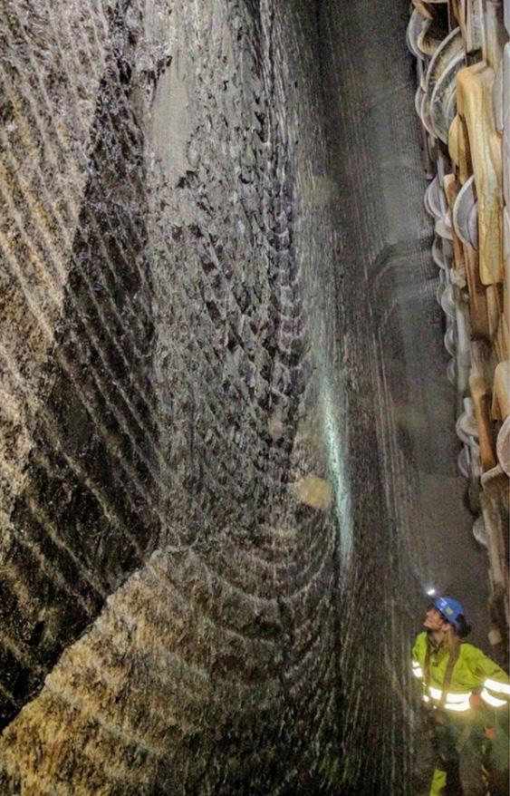
for this contractual arrangement was, should the contractor go bankruptcy during the tunnel construction period, then the equipment could be transferred to a new contractor.
The success of the Follo Line TBM tunnel project was highly dependent on the performance of the four TBMs operating from the centrally located access point at Åsland. In order to cope with the hard rock challenges to be encountered at the project, the most robust TBM design was a must. For hard rock tunnel boring, a stiff cutterhead and a large diameter and high-capacity main bearing, capable to withstand extreme eccentric cutterhead loads, is crucial for the tunnel boring operation.
• Hard rock double shield TBM
• Detailed specifications and design drawings prior to commencement of manufacture to be made available to client
• All parts new and traceable
• Sealable ports in shield
• Core drilling system
• Retractable cutterhead
• Back-loading cutters
• Cutter monitoring system
• Main bearing L10 life: min. 15 000 hours (in compliance with ITA-tech guidelines)
• Fully automatic guidance system
• Automated electronic data recording system –transmittal to surface in real time and available to client at any time
• Gas detection system
• 12 bar water pressure resistance – static
• Water filling of excavation chamber
• Probing and pre-grouting drilling
• Equipment for MWD
• Mapping of probe holes by tele-viewer
• Number of grouting ports
• Number of drilling rigs
• None-flammable conveyor belts
• Automatic fire detection and suppression system
• Refuge chambers in compliance with ITA Guidelines -24 hours stand-up time
Additionally, there were another 40 requirements for the TBM and Backup system, Scope of work, TBM excavation and support, and OH&S.
Four of six pre-qualified international joint ventures submitted bids on the TBM section of the Follo Line tunnel. The international bidders had no or limited experience from tunnel boring in hard and tough rock similar to Norwegian bedrock consisting of gneiss and granites.
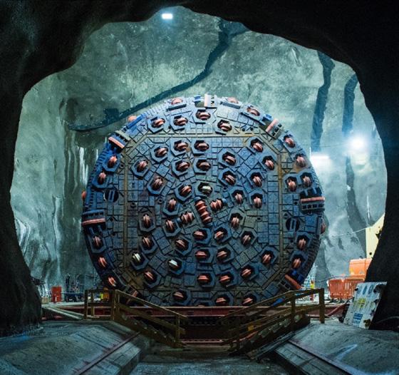
Figure 10-5: Launching of TBM S-982 (photo: AccionaGhella Joint Venture).
The Follo Line organization had personnel with own experience from hard rock tunnel boring in Norway and abroad and who had been cooperating through many years with the Norwegian University of Science and Technology (NTNU), a world leading institution when it comes to hard rock tunnel boring. Therefore, the Follo Line organization was capable to, -, evaluate the technical specifications proposed in the tenders and make their own judgements.
In the original tender, the winning contractor AGJV offered TBMs with technical specification well within the invitation to tender requirements. In the revised tender, the TBM supplier was changed, and some technical specifications were changed prior to signing the contract to further improve the final design of the TBMs.
Bane NOR played a pro-active role in upgrading of the TBM technical specifications during the final design of the four 9.96 m diameter double shield TBMs for the Follo Line tunnel project (Figure 10-5). This includes improved cutterhead and main drive design which resulted in increased stiffness of the cutterhead and a larger-diameter main bearing, with extended L10 life.
Other important design criteria for TBM boring in hard to extreme rock conditions that were focused on as well, were:
• The Main bearing L10 lifetime was extended from 15,000 hours to min. 20,000 hours
• The weight of the cutterhead was increased from 230 to 265 metric ton
• The number of cutting discs were increased from 66 to 71 (70 tracks – the two outermost gage cutters are double tracking) thus resulting in reduced average cutter spacing to 71 mm.
• The cutterhead is equipped with 19in cutters, but the cutter housings are prepared for use of 20in cutters
• The inner and outer main bearing seal arrangement was modified to include pressurized seal rings for 12 bar water pressure resistance during emergency sealing of the TBM shield.
• The size of the Main bearing was increased from 6.0 m to 6.6 m diameter
TBM cutting diameter 9,960 mm with new cutters
Cutter size 19-inch wedge lock, back-loading
Number of disc cutters 4 center (x 2 discs) + 48 face + 15 gage = 71 cutting discs
Load per cutter ring 315 kN
Max. recommended CH load 71 x 315 = 22,365 kN
Weight of Cutterhead 265 metric ton equipped with cutters
Cutter monitoring system 5 cutter positions monitored (positions: 42, 44, 46, 48 and 50)
Cutterhead (CH) power 13 each VFD motors x 350 kW = 4 550 kW
Total power installed approx. 6900 kW
CH rotational speed 0 – 6.06 rpm
Nominal torque 11,115 kNm @ 3.67 rpm
Max. overload torque 16,672 kNm @ 3.67 rpm
Main Bearing (MB) 3 axis roller bearing, 6,600 mm OD
Main bearing lifetime > 20 000 hours according to ITA-tech guidelines
Main Bearing Seals
Inner and outer sealing system, each: 3 lip seals + activatable seal ring for 12 bar static water pressure resistance
Total length, TBM + Backup approx. 150 meters
Total shield length 14,415 mm
Total weight, TBM + BU approx. 2,400 metric ton
Probe Drilling Equipment: Two drill rigs with rod adding system for drilling up to 35 m long holes for probing and pre-grouting through 38 ports in gripper shield with 11-degree angle to tunnel axis and or through 8 openings in the cutterhead.
Table 10-1: Brief final revised TBM specification
Bane NOR requested a third party-verification of the Main bearing (MB) L10 life calculation for the proposed 6,000 mm diameter main bearing according to ITA-tech Report No. 1 – April 2013, and for the design of the cutterhead (CH). Babendererde Engineers of Germany performed a this verification of the main bearing L10 life calculation for the proposed 6,000 mm main bearing and proposed some design changes to the cutterhead.
In order to further minimize the risk of main bearing failures during TBM tunnel construction, the Follo Line management entered into an agreement with the contractor to enlarge the diameter of the MB to 6,600 mm OD, which gives a MB:TBM diameter ratio of 0.66.
Two central TBM launching locations Approx. 18.5 km of the 20 km long tunnel sections was excavated by four TBMs, operating from one centrally located access point at Åsland, close to the main road E6 and with a limited number of neighbors in proximity to the rig area (Figure 10-6 and Figure 10-7). Two access tunnels, each approximately 1 km long, had been excavated from the main rig area and down to the location for the future railway tunnels. Additional auxiliary tunnels and two large assembly chambers were constructed utilizing conventional drill and blast techniques as a preparation for the assembly and operation of the TBMs.
The first of the four Herrenknecht 9.96 m diameter Double Shield TBMs started the boring operation activities in September 2016 and by the end of the year all of the machines were in operation. The TBM excavation was expected to be completed by the end of 2018/ beginning of 2019. Two TBMs were boring in the northward direction toward Oslo Central Station, and two TBMs were working in the southward direction toward the city of Ski, where the bored tunnels were connected to a cut- and cover section.
The location at Åsland and the opportunities to develop a compact site arrangement, including all the necessary operations for the production of the 18.5 km long twin tunnel, provided great
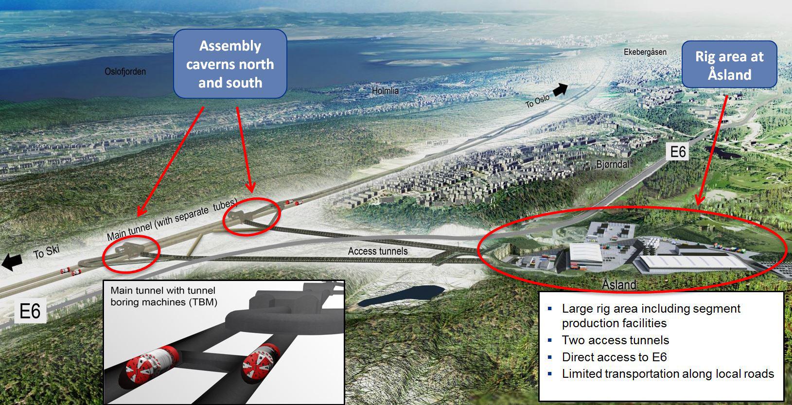
environmental benefits compared to excavation by drill and blast from several different access points. Continuous conveyor belts, transporting the excavated material from the tunnels, have reduced the number of vehicle and traffic movements.
Inside the tunnel, gasketed pre-cast concrete segments were installed in a closed ring to ensure rock support, as well as protection from water leaking into the tunnel. In addition, invert segments were installed inside the segment rings.
The production of these elements took place at Åsland site and approximately 10% to 15% of the TBM spoil was intended to be reused in the pro-
Figure 10-7: An overview of the centrally located rig area at Åsland with the conveyor belt (blue), segment factory, offices, and accommodation for the workers.
The advance rates depended on whether pre-grouting had to be performed or not. The weekly production during weeks without pre-grouting could be more than 150 meters, but it could be reduced to approximately 1/3 in weeks with up to three rounds with pre-grouting.
As a rule of thumb, optimal tip width of the cutter rings for given rock conditions, should be as narrow as possible in order to obtain a good rate of penetration. However, the tip width of the ring should be sufficient to sustain the cutter loads needed to cut the rock efficiently without cutter-ring chipping or “mushrooming”.
duction of these concrete segments. However, due to content of pyrrhotite in the TBM spoil, external material had to be used. This is described in more detail in chapter 9 “Use of the tunnel spoil”.
Launching all four TBMs from Åsland, also enabled reuse of spoil for potential future residential developments within the area. This reduced the volume of traffic on public roads and pollution from vehicles.
Multipurpose Service Vehicles (MSV) were used for transportation of concrete segments and other materials from the storage area at the surface directly to the TBM headings. The shift-crews were as well, transported to/from the TBMs by use of MSVs.
The grout, both component A and component B, for filling the annulus gap between segment rings and tunnel surface was transported through pipelines from the grout plant at surface all the way to the TBM backup system.
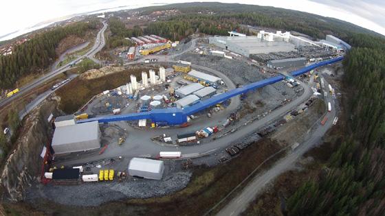
Rate of penetration and advance rates are given in respectable table 10-2 and table 10-3 below.
For the Follo Line TBMs, the contractor tested cutter rings from the TBM-supplier, with different tip-widths, and it was assumed that a low Rockwell hardness of the ring, for hard rock tunnel boring, resulted in a “mushrooming” where the ring tip-width became so wide that penetration per cutterhead revolution was reduced. The contractor experienced, as well, a lot more cutter bearing failures than was expected.
Originally, the client expected the machines to be supplied with a cutter-monitoring system for all the cutter-positions. However, the machines were supplied with a monitoring system for only five cutterpositions, but for some reason they were never used. From the clients point of view, use of a monitoring system connected to all the cutter-positions would have given an early warning of cutter failure.
Based on previous experience from boring in similar Precambrian gneiss rocks in Norway, it was assumed that cutter life would in the range of 200 m3/ cutter change. These expectations were fulfilled.
From the clients point of view, the cutter thrust could have been utilized more efficient during the excavation in order to achieve an even better rate of penetration. A high degree of cutter-thrust is linked to the quality of cutters. Unfortunately, cutters from all suppliers with relevant experience from hard-rock
TBM tunnelling, were not tested during the excavation of the tunnels.
According to the TBM requirements the double shield machines were supposed to be designed to withstand 12 bar water pressure during emergency sealing of the TBMs.
One of the machines bored into a fracture zone, which gave heavy water leakage and the attempt of the contractor to seal off the TBM failed. The system was never used again.
The first of the four 9.96m double shield TBMs started boring operation activities in September 2016 and by the end of the year all of the machines were in operation. The two TBMs boring in the northward direction toward Oslo Central Station started the boring operation approx. five months ahead of schedule and broke through into an underground cavern in September 2018, still approx. five months ahead of schedule. In February 2019, the two TBMs working in the southward direction, toward the city of Ski, broke through into the cut-and-cover transition to a surface approach to the Ski railway station two months behind schedule. This was mainly due to pre-grouting in sensitive areas. In total, the entire TBM excavation were finalized within the contract schedule.
The success of the Follo Line TBM tunnel project was highly dependent on the performance of the four TBMs. In order to cope with the extreme hard rock challenges to be encountered at the project, the most robust TBM design was a must.
Bane NOR has played an active role in specifying the technical TBM requirements. Ultimately, TBM requirements included upgrading cutterhead and main drive design, resulting in increased stiffness of the cutterhead, reduced cutter spacing and a larger diameter main bearing with an extended L10 life.
AGJV supplied the TBMs for the Follo Line tunnel project in accordance with the final TBM specification requirements of Bane NOR.
At the end of all excavation in February 2019, these upgrades have proven to be justified. The TBMs performed as expected.
Bruland, A. 1998. Hard Rock Tunnel Boring. Doctoral Thesis, Norwegian University of Science and Technology, 1998:81.
Kalager, A. K. 2016. The Follo Line project-a large project that includes a complex excavation of the longest railway tunnel in Norway. Proc. World Tunnel Congress 2016, San Francisco.
Snowdon R.A., Ryley M.D, Temporal J. and Crabb G.I., 1983. The Effect of Hydraulic Stiffness on Tunnel Boring Machine Performance, Int. J. Rock Mech. Min. Sci. & Geomech. Abstr.,Vol. 20, No. 5.
Hansen, A. M., Bruland, A., Syversen, F. S. G., Johannessen, S. Tailor-made TBM design for boring in extreme hard rock conditions and examples from the Follo Line tunnel project. WTC 2017, Bergen.
The entrance of the two Follo Line tunnels to Oslo Central station had to satisfy all the requirements needed to ensure the access to the necessary platforms without any conflict with the other tracks going in and out of that busy station. Furthermore, the Directorate of Cultural Heritage had several requirements linked to the preservation of Medieval cultural heritage areas close to the station. Because of this, the existing Østfold Line had to be relocated close to Oslo Central station.
Moving south from Oslo Central station, the Follo Line crosses under the Medieval park and a track area, called Loenga, in a concrete culvert. The culvert leads to the Ekeberg Hill, where the Follo Line tunnels and the inbound Østfold line continue in rock tunnels. The outbound Østfold Line continues
in the existing track along the harbor on the outside of the Ekeberg Hill, 1,7 km to Sydhavna. At this point, the inbound Østfold line exits the tunnel, connect with the existing track, and continues south.
The Follo Line continue south towards Ski, in two 20 km long tunnels, see figure 11-1.
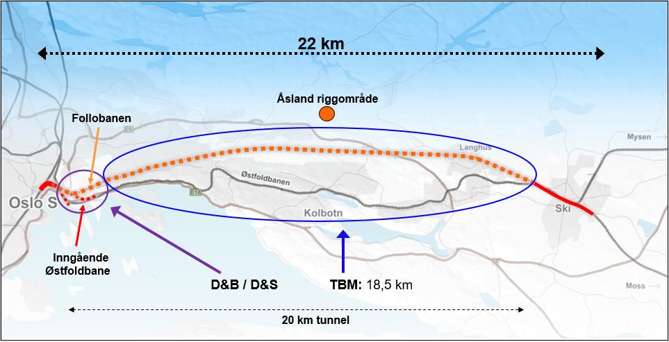
In this northern part of the tunnel, the two Follo Line tunnels and the Inbound Østfold-Line tunnel are crossing close to other sensitive infrastructure, as different tunnels, caverns, and technical installations. See figure 11-2 and 11-3.
To avoid damages of the objects which were located close to the new tunnels, specific preparations were done in advance and other suitable mitigations were implemented during the excavation of the tunnels.
Figure 11-2: Map of the tunnels in the northern part of the Ekeberg Hill. 1) Three Track Tunnel, 2) Inbound Østfold Line, 3) Inbound and outbound Follo Line tunnels, 4) Access tunnels and technical rooms, 5) Alna river tunnel, 6) E6-Ekeberg tunnel, 7) Petroleum storage caverns.
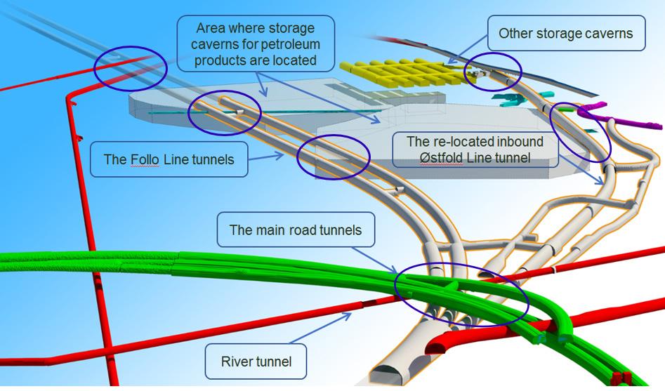
Figure 11-3: Existing and new infrastructure in the Ekeberg Hill. The blue circles indicate the areas where the crossings between the new and existing infrastructure occur, during the construction of the Follo Line project.
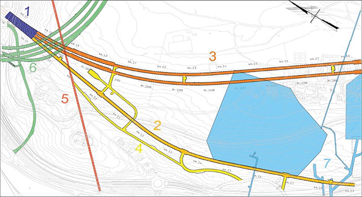
The three railway tunnels cross under the E6 main road tunnel and under the exit and entry ramps for the road tunnels. The distance between the crown in the railway tunnels and the invert in the road tunnel is at smallest 3.5m. Between the railway and the road tunnels is a tunnel for the Alna river located, going from the Kværner valley down to the harbor. At an early stage in the planning, this crossing was pointed out as a critical crossing due to the low overburden between the new and existing infrastructure
There are strict requirements when planning the geometry of new railway tracks. Due to the geometry of the Follo Line it was not possible to avoid crossing close to the caverns for storage of petroleum products. Approximately 1 km inside the Ekeberg Hill all the three railway tunnels come close to, or cross above some parts of the storage caverns or their infrastructure. This includes the caverns, technical installations controlling the pumping of the petroleum products, in addition to ventilation systems. The storage caverns supply most of the area surrounding Oslo with petroleum products, including Oslo airport Gardermoen. Therefore, any disturbance in the delivery chain would have severe economic and societal consequences.
From the storage caverns with petroleum products, there is a 2 km long escape tunnel. It was not possible to avoid conflict between this tunnel and the two Follo Line tunnels. In accordance with the agreement with the owners, the escape tunnel had to be open and operational throughout and after the construction period. The solution was to build a bypass tunnel under the new Follo Line tunnels. This by-pass had to be finalized and in operation before the construction of the two Follo Line tubes could take place.
The tunnel entrance for the inbound Østfold Line is very close to the existing track. The portal comes out on a plateau underneath a concrete bridge construction for the E18 main road. Thus, the construction was planned to take place close to a highly trafficked main road and railway line, as well. The access to the site was challenging and was a critical element in the project. There were linked several restrictions to the work to avoid damaging the existing infrastructure or disturbance of the traffic on both the road and the railway.
The two Follo Line tunnels cross right under the old Kværner sewage tunnel and right above the new Midtgardsormen sewage tunnel, in an area where the two sewage-tunnels also cross each other. The distance between the Follo Line tunnels and the Kværner tunnel is at the smallest approx. 1,35 m. The Kværner tunnel is an old and unlined tunnel where the blasted profiles vary. Between the Follo Line and Midtgardsormen, the smallest distance is ca 0.5 m. The new sewage tunnel was built during the design phase of the Follo line, and exact information with respect to location and design were available. This crossing for the Follo Line tunnels was performed by the two tunnel boring machines (TBM).
In an early stage of the project, it was determined that it would not be suitable to excavate the inbound Østfold Line tunnel by a TBM. It was not space enough to neither assembly nor disassembly a TBM in none of the ends of this tunnel section. It was therefore decided to excavate the inbound Østfold Line by using careful drill and blast methodology.
It would have been possible to continue the TBM excavation from the south, for the two Follo Line tunnels in the northern part of the Ekeberg Hill. This, however, would have been the last part of tunnel excavation of 10.5 km, and it would have been on the critical path for the entire Follo Line project. To reduce the risk of delaying the entire project, it was decided to excavate the northern 2 km of the 20 km long tunnel by careful blasting. To ensure a good progress on this part of the project, the work was performed as a separate contract, awarded early and independent of the TBM-contract. This is described in more detail in Chapter 2 “Excavation method for the different parts of the tunnel”
The owners of the nearby infrastructure were critical to the use of explosives close to their sensitive systems. As a compromise, it was decided, after careful consideration, to excavate the parts of the new railway tunnels closest to the road tunnels and the storage caverns by drill and split.
The drill and split performance is an extremely gentle method of excavation. By mechanically breaking the rock by using a hydraulic jack, blasting can be avoided altogether. The method is based on drilling a pattern of 1.5-2 m long holes, approximately 450500 holes on 70 m2 profile. Afterwards, the hydraulic jack is inserted into the holes and expanded, thereby breaking the rock, see illustrations in figure 11-4. The progress was approximately 0.5 m per day, but since
this part was made into a separate contract, the drill and spilt method could be started early to avoid any delays to the project. The agreement with the own-
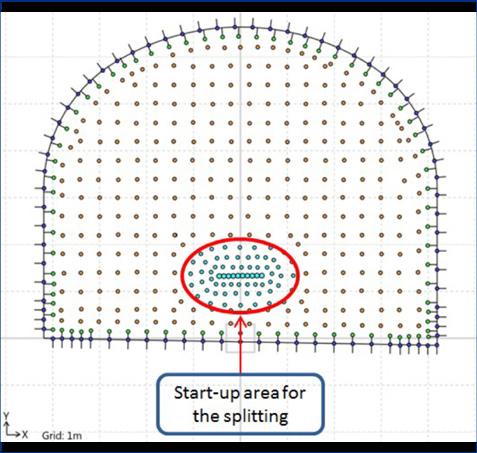
ers of the sensitive infrastructure entailed splitting approximately 1000 m of tunnel.
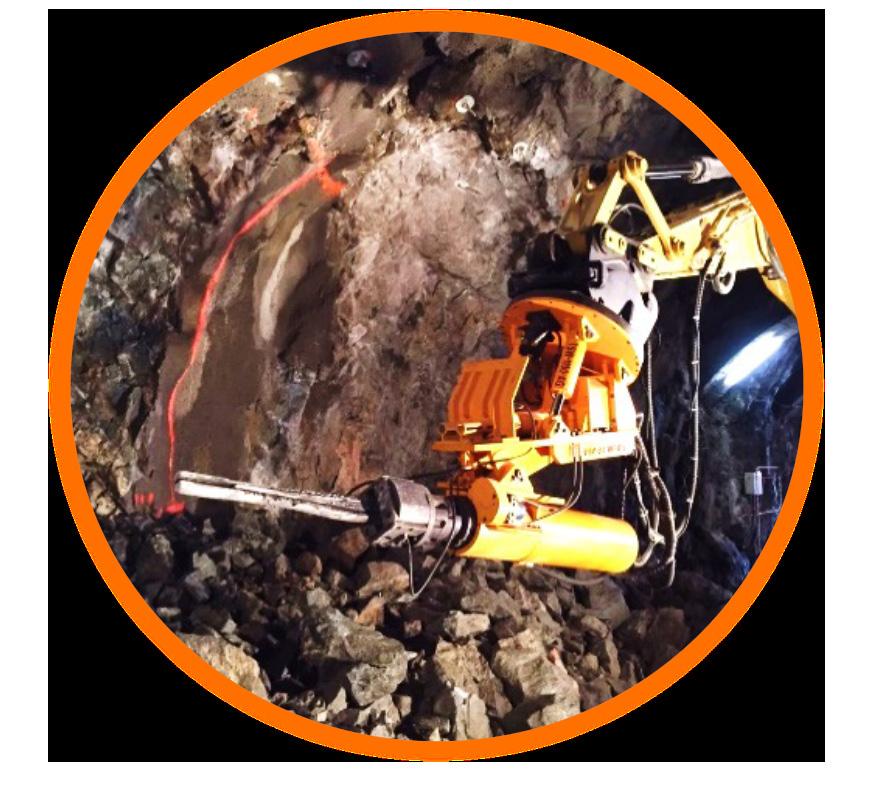
The Alna River tunnel was excavated in 1922, during the construction of the railway in the Loenga area close to Oslo Central station. During the design phase of the Follo Line, it was estimated to be approximately 0.7 m between the crown in the inbound Østfold Line tunnel and the invert of the river tunnel. Several alternatives were considered to ensure a safe excavation under the river. One of earliest designs comprised a large-scale relocation of the river tunnel in the area close to the new railway tunnels. The contractor suggested an alternative of
strengthening the invert of the river tunnel to save both cost and time. The solution was based on curbing the river and guiding the water through pipes. Then the exposed invert was reinforced and casted with concrete, see cross section in figure 11-5.
The first of the three crossings with the Alna River happened quite early in the project. In order not to delay the project, a pilot tunnel with reduced profile was excavated underneath the river, while the work with reinforcing the river invert was completed. This ensured the continued progress of the project northward.
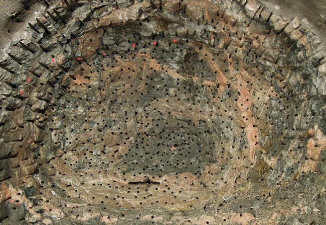
The execution of the crossing An access tunnel was excavated by blasting into the river-tunnel, in order to transport equipment and workers in, in addition of establishing a rig area close to the crossings. Before the work inside the river started, the river tunnel was inspected, surveyed and additional rock support were installed. A subcontractor was hired with expertise on underwater constructions, and divers transported steel pipes up the river from the tunnel entrance by the harbor. To enable the transport of the pipes, the water level had to be increased by curbing the river. Two steel pipes with 2 m diameter were placed next to each other to ensure the capacity of the river throughout the construction period, see figure 11-6. At the entrance and the exit of the pipes, sandbags were used to build dam walls to guide the water into the pipes and expose the invert. To keep the water level low underneath the steel pipes, pumps were continuously pumping out the remaining water, see
figure 11-7. The divers used boats to transport all the necessary equipment in and out from the pipes. The steel reinforcement was transported in, and then placed at the bottom of the river-tunnel, and pipes were installed along the wall to pump the concrete to the crossing areas.
The reinforcement of the crossing areas was done in two rounds. First the area crossing the inbound and outbound Follo Line tunnels was reinforced and casted. Then the dam walls were torn down and the pipes moved downstream, above the area crossing the inbound Østfold Line. The dam walls were rebuilt, and the water removed from under the pipes. After the invert was reinforced and casted, the pipes were removed and transported out. The capacity of the river was reset, and a successful crossing of the three railway tunnels could be performed. The works in the Alna River started in January 2017 and finalized in March 2018.
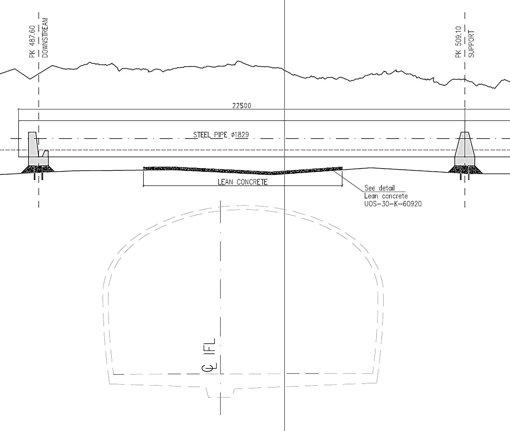
Even though the alternative solution saved both cost and time, there were several challenges during the crossing of the river. One of the most time consuming aspects were the periods with heavy rain. When raining, the water level became too high and the water flow too strong to continue to work in the river. Sometimes this caused hours of waiting, sometimes days. In addition, during periods when the capacity of the nearby water treatment plant exceeded its limits, the overflow went directly into the Alna River. This caused illness among the divers. Simultaneously with the work in the river, blasting took place in other parts of the tunnel system. Because of the age and low level of rock support in the river tunnel, the divers had to evacuate to the access tunnel when blasting was performed in some of the tunnels nearby. This required good radio communication and lead to more waiting time.
Because of the low overburden between the railway tunnels and the Alna River tunnel it was necessary
to install heavy rock support; reinforced shotcrete, spiling, lattice girder, vertical bolts, and watertight concrete lining. The excavation was done by drill and split to avoid any vibrations.
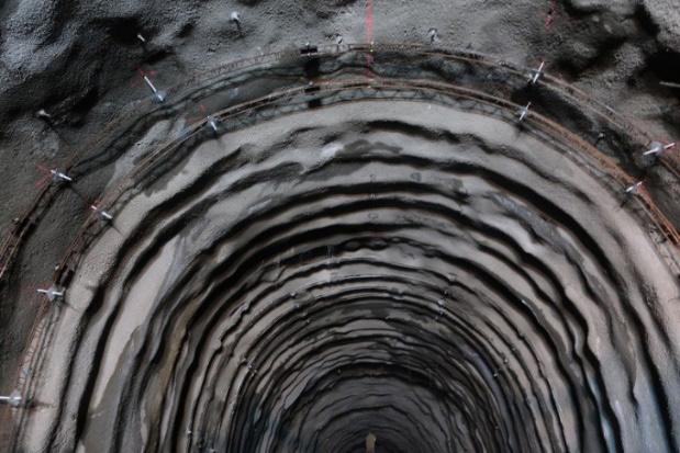
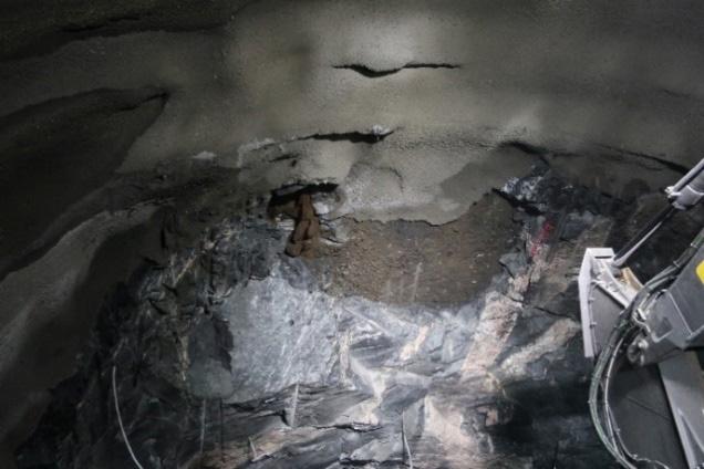
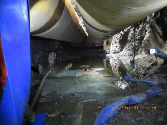
The distance between the two Follo Line tunnels and the Alna River tunnel was approximately 5 m, and the crossings were successfully performed, without any unforeseen events. The distance between the crown of the inbound Østfold Line tunnel and the bottom of the river tunnel was estimated to be approximately 0.7 m. When the reduced profile of the inbound Østfold Line tunnel was excavated to the full profile, around 5 m2 of the concrete plate on the bottom om the river tunnel was exposed, and there were some leakages into the tunnel below. After installation of the rock support, the leakages were stopped by careful grouting. After casting the watertight lining, no further leakages into the railway tunnel were observed. The Alna River tunnel was restored to its previous capacity and the crossing was deemed successful.
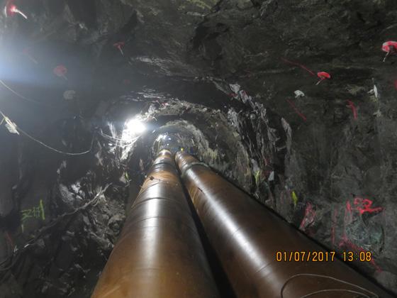
Crossing under the E6 Ekeberg tunnel was one of the most critical crossings due to the low overburden, a fracture zone and strict vibration restrictions. Each day, approximately 70 000 vehicles pass through the E6 Ekeberg tunnel. This is one of the main roads in and out of Oslo, and it was a clear requirement not to disturb the traffic during the construction of the three tunnels.
Before the excavation was allowed to start, the Norwegian Public Roads Administration had several
requirements for this crossing. It was installed a comprehensive vibration surveillance system and planned for regular inspections in the road tunnel before and throughout the construction period. In addition, the stress situation around the tunnels were carefully monitored by doorstoppers and extensometers, installed both in the railway tunnel and in the road tunnel. This is illustrated in figure 11-10. Because of the strict vibration limitations, the excavation was done by drill and split.
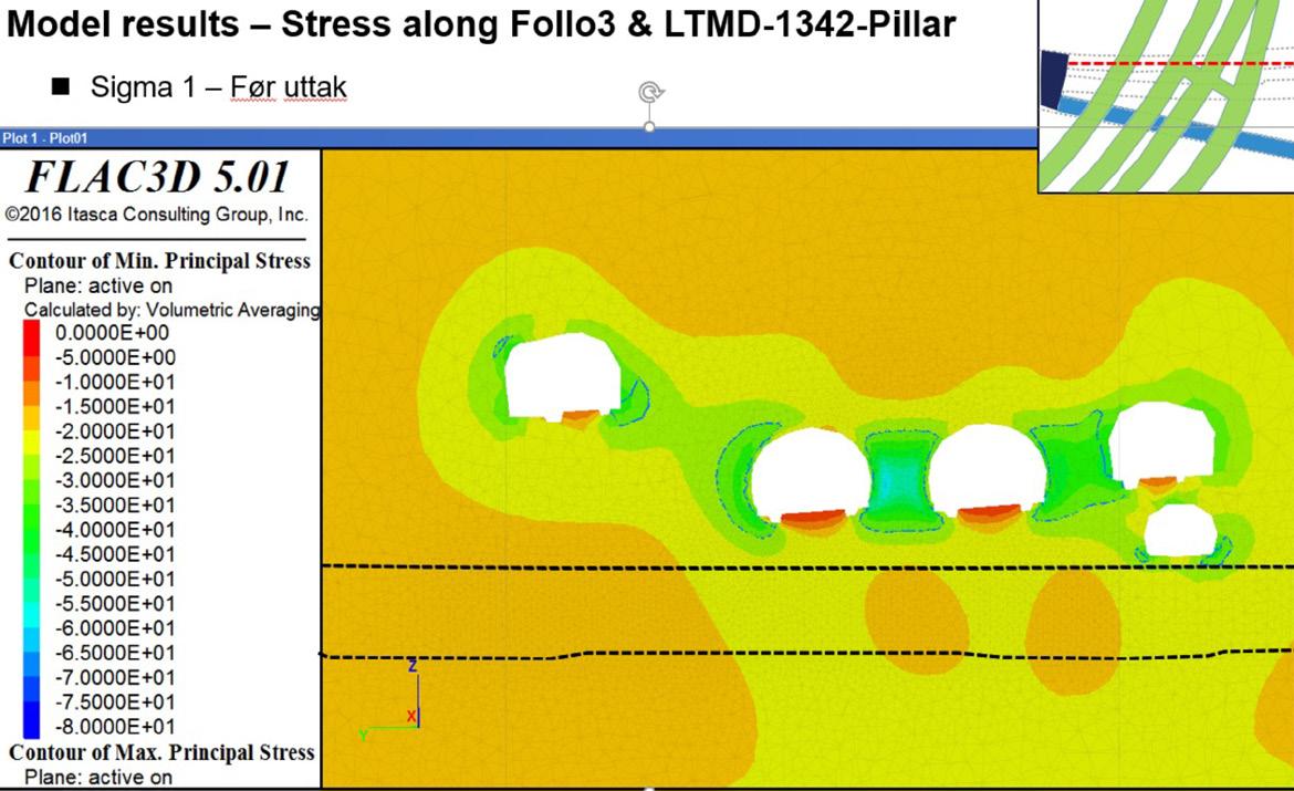
The overburden between the crown in the inbound Østfold Line and the ditch in the road tunnel is approximately 3.5 m. In addition, a known fracture zone crossed through the tunnel within the same area as the overburden was low. Based on the mappings from the former excavation of the road tunnel, the location of this fracture zone was known at an early phase of the planning. However, to get the exact location of the zone, core drillings were performed before the start of the crossing. Because of the low overburden and the fracture zone, it was decided to install heavy rock support for the inbound Østfold Line tunnel through the entire crossing zone under the Ekeberg tunnel, see figure 11-11.
Using drill and split as the excavation method, with only 0,5 m progress every day, ensured a safe and controlled crossing and installation of the rock support. The rock support in the crossing area consisted of systematic bolting, reinforced shotcrete, 8 m spiling, vertical bolts and lattice girders covered by shotcrete. Water and frost protection consisted of a draining layer, sheet membrane and casted lining. During the drilling of control holes in the fracture zone, some water leakages were discovered, which was stopped by pre-grouting with silica-gel. Because of the mitigation measures taken and the careful monitoring before and during the excavation, the crossings were successfully completed without any unforeseen incidents or damage to the existing infrastructure.
Figure 11-11: Overview of the crossing of the inbound Østfold Line and E6 Ekeberg tunnel. The drawing shows the smallest distance between the ditch and the crown (3.5 m), the estimated location of the fracture-zone and the heavy rock support.
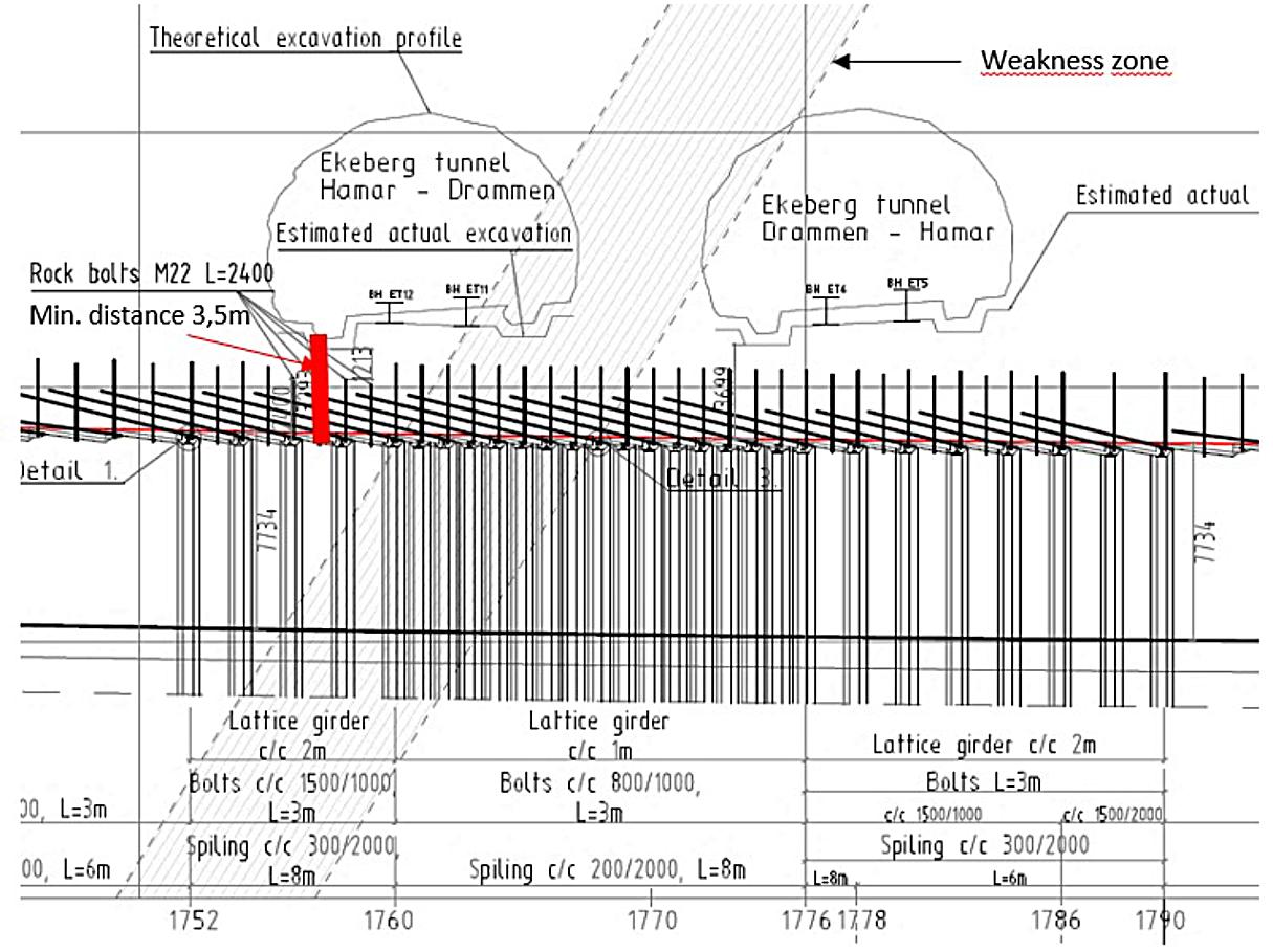
Crossing close to the caverns for storage of petroleum products
In connection to the caverns for storage of petroleum products, there is a large system of interconnected infrastructure. The caverns were built as unlined rock caverns during the1960’s and 1970’s. They use the ground water pressure to keep the petroleum products in the caverns. In addition, there are access tunnels, escape tunnels, ventilation systems and other types of surveillance systems. This whole system is very sensitive to vibrations, and drill and split was planned for the excavation of the railway tunnels through the most critical sections. The crossing took place in two areas.
(1) Crossing between the inbound Østfold Line and maintenance and escape tunnels
(2) Crossing between the Follo Line tunnels and the petroleum caverns.
Crossing between the Inbound Østfold Line and the maintenance and escape tunnels.
The inbound Østfold Line tunnel crosses several maintenance tunnels and one escape tunnel from the petroleum storage caverns (figure 11-12). Before the startup of the excavation, Bane NOR and the owners of the caverns made a careful assessment of the cavern system. One of the most sensitive parts was the ventilation system. By upgrading this, the tolerance for vibrations was increased. After the upgrade, the scope of drill and split could in some areas be replaced by careful blasting, which increased the progress significantly. The vibrations were carefully monitored throughout the excavation. If they came close to the limits, then the excavation was done by drill and split instead. By carefully monitoring the vibrations and adjusting the excavation method, the crossing was successful, without any damage to the existing infrastructure
Crossing of the Follo Line tunnels and the petroleum caverns.
The two Follo Line tunnels cross the petroleum storage caverns with very small distances. Because of the sensitive nature of the infrastructure and the small distances, the vibration limitations were strict, and the tunnels were excavated by a combination of drill and split and careful blasting. Because of the possible leakages from the petroleum caverns, a continuous gas monitoring system was installed. In addition, the closest caverns were emptied in the most critical period when the excavation took place close to the storage area.
The greatest concern was still that the groundwater around the petroleum storage caverns would drain or be lowered due to the tunnel excavation. To reduce this risk, several water curtain screens were
drilled above the caverns, and water continuously pumped into the rock to maintain the water level. In addition, the groundwater level was carefully monitored daily. The water curtain was maintained until the excavation was finished and the lining installed. In the section above the caverns a gas tight membrane and full profile lining cast was used to keep the groundwater at the required level. The monitoring of the groundwater was continued for a while after the lining had been installed, and no changes of the water level, caused by the tunnel excavation, were observed.
Crossing and culvert design of the escape tunnel from the petroleum caverns North of the contract boundary between the EPC TBM and EPC D&B, the two Follo Line tunnels would cross right through the escape tunnel from the petroleum storage caverns. As described earlier, it was a requirement that the escape tunnel should be in operation 24/7 throughout the entire constructions period. To fulfill this, a by-pass had to be built under the new railway tunnels, with stairs to connect from both sides to the existing escape tunnel. See figure 11-13. In the design phase, it was considered easier to build the by-pass from a drill and blast tunnel, than from a TBM excavated tunnel, therefore the boundary line was set just before the escape tunnel.
The escape tunnel is approximately 2 km long and has a cross section around 8 m2. The by-pass was built below the future railway tunnels. At each end of the by-pass, this was connected to the existing escape tunnel.
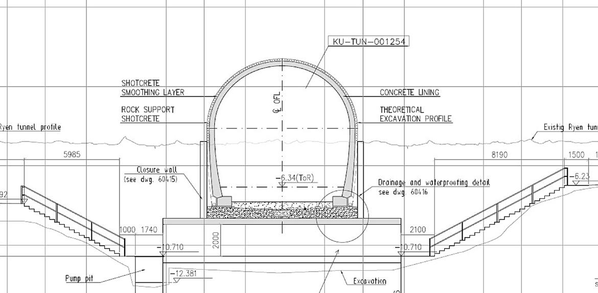
The crossing of the new railway tunnels with the escape tunnel that had been replaced, was performed by careful blasting. During this crossing, old
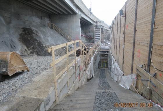
explosives were discovered in the old escape tunnel, and had to be removed carefully before the work could continue.
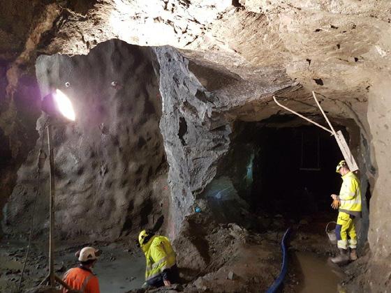
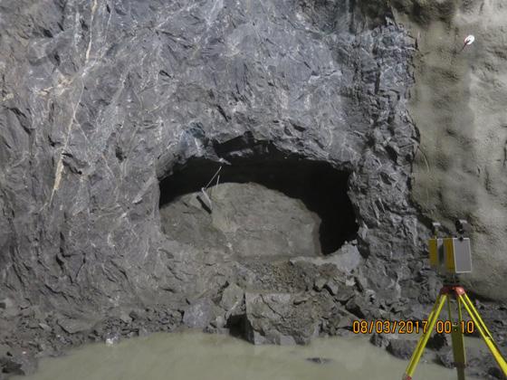
Figure 11-15: Profile of the tunnel at 8m2 Figure 11-14: Careful blasting at the crossing.
Establishing the southern portal for the inbound Østfold Line at Sydhavna
The Inbound Østfold Line exits the tunnel section and is connected to the existing track on the Østfold line at Sydhavna. The portal was to be constructed in a cramped area, underneath the road E18 Mosseveien and between the rock surface and the existing Østfold Line track. Below the railway is the entrance tunnel to the Ekeberg storage halls. Because of the low overburden, strict vibration limitations and poor rock quality, the excavation of the tunnel was performed by drill and split, and heavy rock support was installed. Because of the small distance to the road, the breakthrough could not be completed until the portal was completed. The design of the portal was carefully considered by both Bane NOR and Norwegian Public Roads Administration before construction.
Before the construction of the portal, an access road was blasted and dug out up to the rig area (figure 11-16). The access tunnel to the Ekeberg storage halls were used at the access point. After reaching the site, a wall was built between the construction site and the railway track close by, so that the construction could continue without disturbing the railway traffic. To strengthen the rock between the portal of the inbound Østfold Line and the road, rock support was installed, both bolts and shotcrete were used (figure 11-17). In addition, the ventilation tower used by the Ekeberg storage hall had to be torn down and rebuilt in another location, to avoid conflict with the new railway tracks.
Figure 11-17: Rock support under the E18.
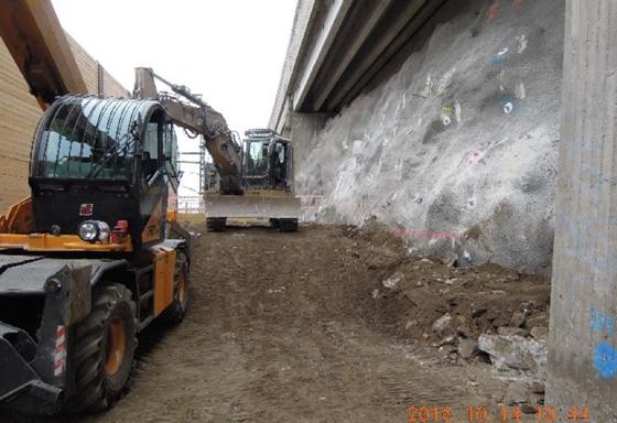
To excavate safely under the E18 Mosseveien the rock below the road was reinforced by core drilling and installing H-beams. Afterwards, the beams were grouted and extended out into the portal (figure 11-18). The outer wall of the portal was reinforced and casted up under the H-beams and then the beams were casted into the roof of the portal. After finalizing the portal, the last few meters of
tunnel were excavated by drill and split. Heavy rock support was installed, then the lining was casted. Throughout the construction, the vibrations were carefully monitored, and the construction site was regularly inspected by the Norwegian Public Roads Administration. The portal was completed without any damages to the nearby infrastructure (figure 11-19).
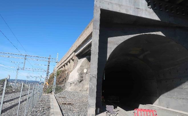
Before crossing with the TBMs between the sewage tunnels Kværner and Midtgardsormen, some preparations had been made. During the construction of the Midtgardsormen tunnel, they reinforced the section of the crossing with rebars in the crown of the sewage tunnel and a concrete lining. The distance between the Follo line tunnel and the sewage tunnel was approximately 0.5 m. Then it was prepared for a safe crossing by the TBMs above the Midtgardsormen tunnel.
To avoid any leakages from the Kværner tunnel into the Follo line tunnels, the sewage was led from the Kværner tunnel and into the Midtgardsormen tunnel before the crossing with the TBMs took place. This was done by raise drilling from the surface, down
into the Kværner tunnel and further down into the Midtgardsormen upstream of the crossing-point with the Follo Line tunnels. Then, the excavation of the two Follo Line tunnels could be performed just beneath a dry Kværner tunnel. As soon as the lining was installed in the two Follo Line tunnels, the connection between the two sewage tunnels was closed, and the sewage could continue to flow through the Kværner tunnel.
Before the first crossing with the TBM and the Midtgardsormen tunnel, the TBM stopped above the crossing point for inspection of the reinforced lining below. Surprisingly, the concrete was missing, and only the rebar was present in an 18 m2 section.
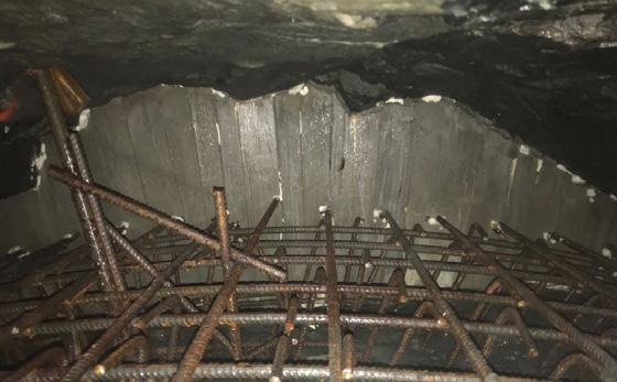
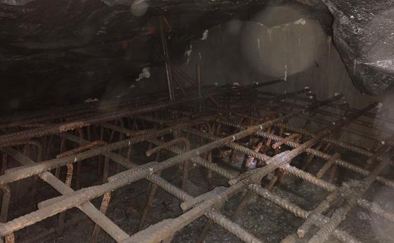
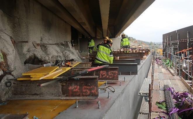
This resulted in a few days stop for casting the reinforced lining in the crown of the Midtgardsormen tunnel before the machine could pass above. When crossing the Midtgardsormen with the second tunnel boring machine, the lining was completed as expected, and there were no further surprises. The crossing was completed within a few hours.
All the crossings of the new railway tunnels, at the Follo Line project, with existing infrastructure, has been completed without damaging any nearby objects. The lessons learned have been that good knowledge of all the existing infrastructure is vital and all the necessary preparations must be completed before starting the crossing. Cooperation and communication with the owners of the infrastructure was essential to the success. One of the most important tools for both the planning of the performance as well as for communication with the owners, was an up-to date 3D-model with all the objects based on updated surveys. It was also important that both client and contractor had contingency plans to handle any unforeseen events in case of surprises.
The well planned preparations and the careful execution of the tunnel excavation resulted in a successful performance of the crossing of the sensitive infrastructure. No damages occurred.
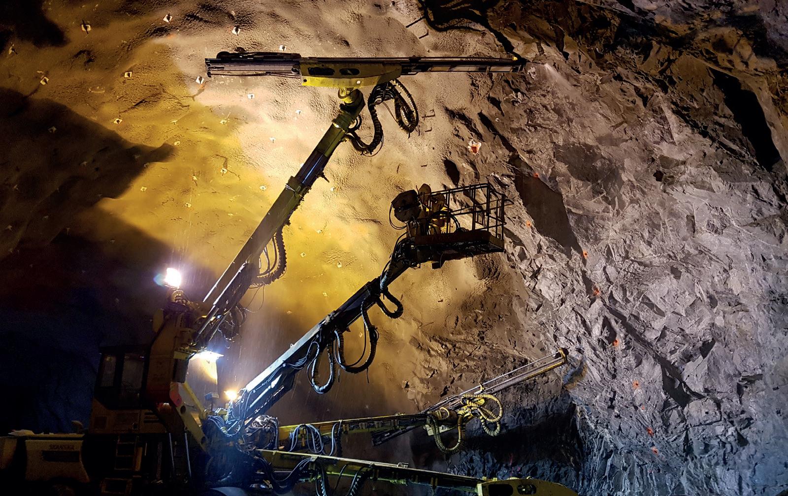
• 37.000 m TBM tunnel.
• 9 M tons of rock
• 140.000 concrete segments
• 1 M m3 of concrete
• 350 km of auxiliary pipes
• 1,000 workers - peak
• More than 25 nationalities
The configuration of the area where the project was settled is an approximately 200,000 m2 of platform, close to the motorway (E6), and it includes the area for the spoil.
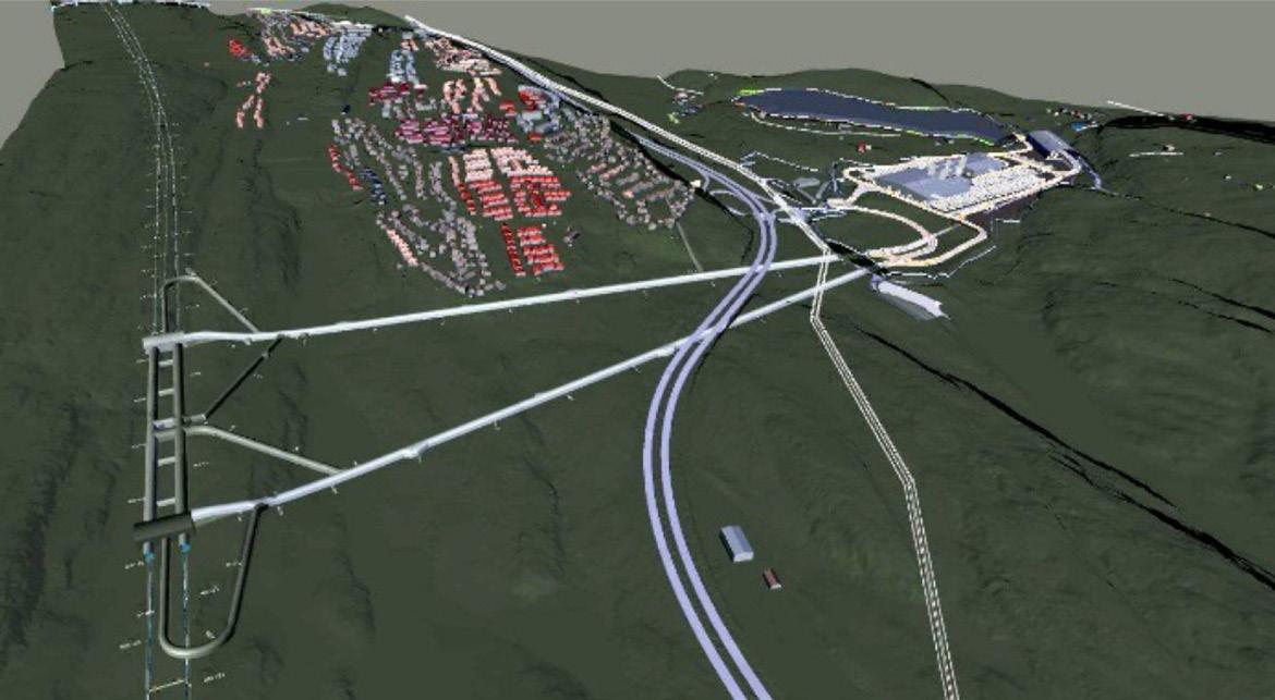
The two access tunnels from the rig area down to the future railway tunnels were excavated as prework contract before AGJV started. As part of AGJV scope, it was necessary to excavate additional parts of the access tunnels, transport and auxiliary tunnels and assembly caverns where the machines were going to be assembled. This activity was contemporary with the execution of the civil works for the factories, auxiliary installations, and TBM assembly. The arrangement for the rig area and the tunnel system is illustrated in figure 12-1 below.
The first complex task was to define and integrate the whole number of factories and installations that where needed, assuming that the time factor was critical. The contract was signed the 23rd of March 2015, and the land was provided by Bane NOR the 18th of June 2015. The target schedule that AGJV settled, was to start boring with the first TBM by September 2016, and the fourth and last one, by December 2016.
In order to achieve that aggressive schedule, AGJV design team (Acciona Ingenieria was the design company for the Follo Line EPC TBM project) worked very hard on the first 6 months of the project with all different AGJV production teams, until a final compact solution was defined and agreed between all. Finally, four different areas or platforms where established and would include all the factories and auxiliary installations: precast factories, spoil area, portals (lower area) and auxiliary tunnels area. All four areas were linked and integrated from a logistical point of view and the final result was a very compact and efficient industrial/production “city”. A detailed description of those areas will follow in the next sections.
On top of the challenge of design, procurement, preassembly on factory, disassembly, transport to the site and final assembly on site of the four TBMs, in order to start the excavation of the tunnels with enough time slack, it was needed to have around 2,500 precast concrete rings minimum storage on site before the start-up of the TBMs. Therefore, the
precast factories had to be assembled and start the production months well in advance of the TBMs.
After some months of analysis and evaluation of what was designed during the tender process by Acciona and Ghella, and what the new challenges and reality of the area provided, the first critical decision taken was to reduce from four precast factories, as previously agreed, to three.
Figure 12-2: The original design with four precast factories.
Figure 12-3: The new design with three precast factories.
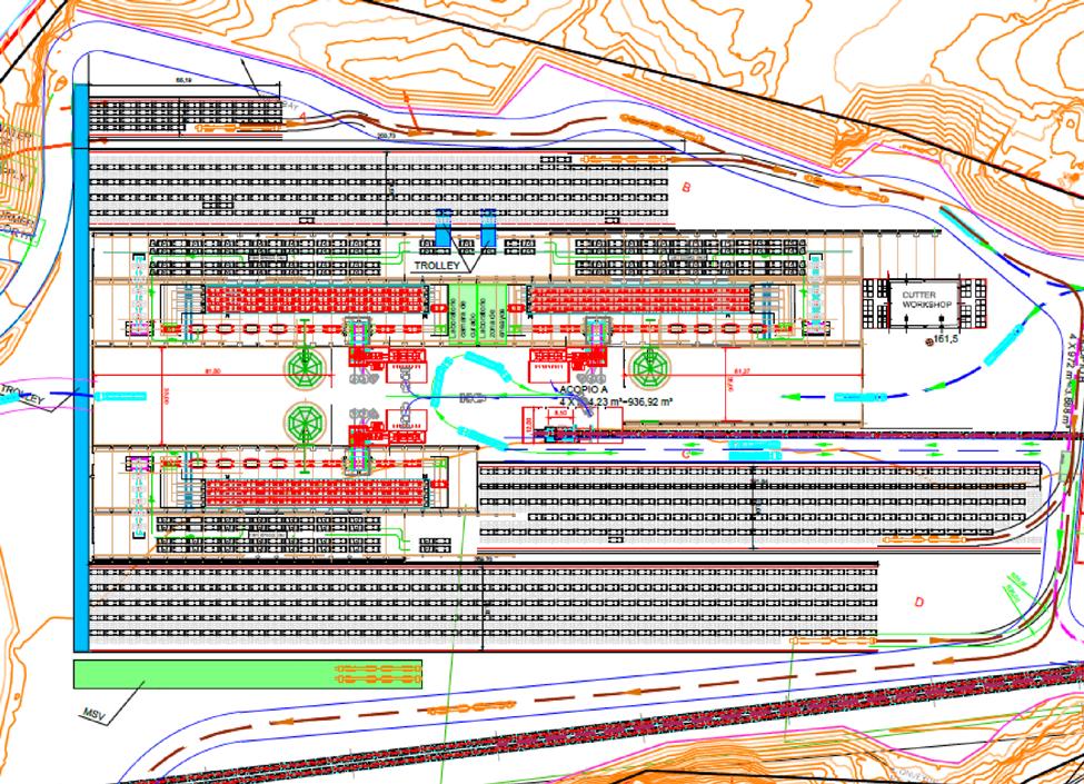
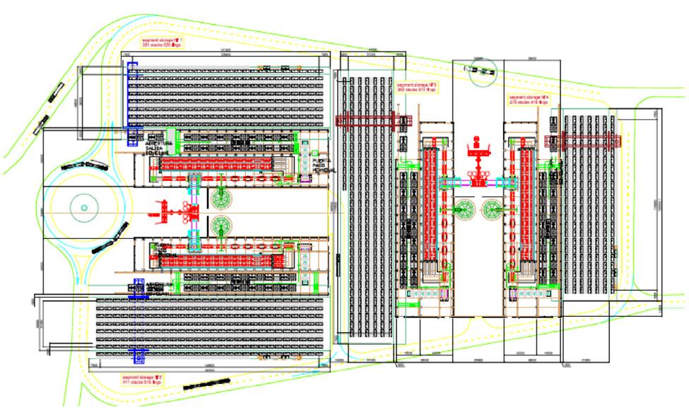
Figure 12-4: The spoil shed (large building) with the conveyor belt (blue) and the building for storage of aggregates (four openings).
That decision was based on an optimization on the area for storage segments. Three factories gave more space for storage. Assuming that with three factories and with time enough for starting the precast rings production in advance, the risk of not having enough rings for the TBMs was controlled for the entire construction period.
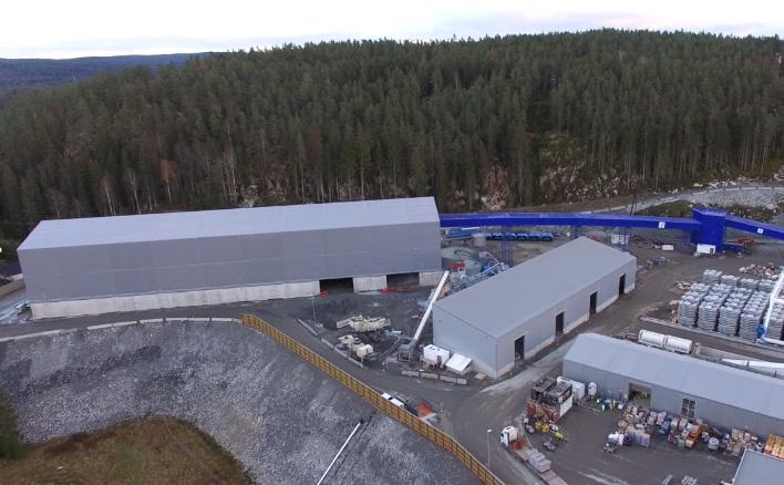
The second area that required intensive analysis and different solutions till achievement of the final optimized one, was the spoil shed, where the material excavated from the TBMs was going to be managed, and the crushing plant area for production of aggregates from the excavated rock. The result of the intention of using the crushed spoil as aggregates is described in Chapter 9 “Use of the tunnel spoil”.
The spoil area had to be covered to allow working during the winter and during night time. It integrated into the crushing plant area. The final solution was a massive shed covering the spoil, where the conveyor belts were integrated and aligned, and a second shed for the storage of crushed aggregates produced by the crushing plant adjacent to it.
The building for storage of the aggregates were divided in four chambers, each for the different sizes of aggregates needed for the production of segments. Through ports integrated in the floors of the four caverns, the aggregates were dropped down on an underground conveyor best, which brought the aggregates up to the three batching plants for each of the segment factories. The integrated solution included a surrounding wide transit road for dumpers and road trucks, as both would be needed on different stages of the project.
Both the precast and spoil area were placed at level 169. The adit tunnel entrance, where the access to the main tunnels were placed, was at level 150. This difference of levels was another challenge in terms of logistic optimization for the rest of the installations. Final design of the lower level was integrated in the confined space that the excavated portal area created, plus the tunnels access and necessary wide logistical roads. In this area the grouting plants, water treatment plant, substations, workshops, and warehouses were finally allocated.
Figure 12-5: Lower area close to the tunnel access portals and installations associated to the tunnels.
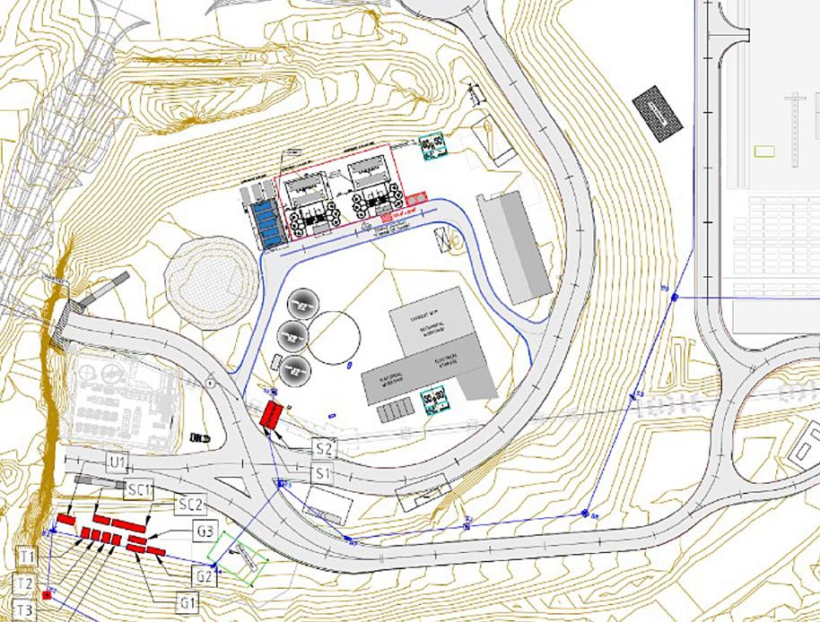
The fourth key area of the project were the auxiliary tunnels and assembly caverns. This area had the challenge of combining the intensive traffic that the vehicles getting into the tunnel were producing and the allocation of all tunnel auxiliary installations (ventilation, pipes, electrical cables, and conveyors).
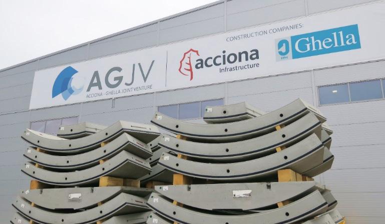
Two assembly caverns located North and South to the adit access tunnels were designed for the
assembly and launch areas for the TBMs. It had to be big enough and at the same time be integrated into the final permanent tunnel design. Final dimensions of the caverns were 22(H) x 25(W) x 50(L) m.
In each cavern, two TBMs were assembled at the same time. A jacking crane system was selected as the most compacted and polyvalent lifting equipment for that kind of confined space and complex assembly operation.
The integration and coordination of all the equipment installed into the four main areas previously described above, were one of the key elements and success factors for the tunnel excavation on the EPC TBM Follo Line project. In addition, a common “construction green” area, that included offices for both client and contractor (white and blue collars), barracks for 450 workers and a 24/7 canteen, were assembled.
As a final general comment, all the design took into consideration the extreme weather conditions (-25º C) that the site area could suffer during wintertime by installing full covered conveyors, heating cable on asphalt and heated pipes as some examples.
In the following section, a summary of the main equipment and auxiliary plants will be presented.
Precast factories, batching plants, and cranes AGJV built a large concrete segment factory at the construction site to supply concrete precast elements continuously to the TBMs. The entire area for the three factory is about 20,000 m2 and had three production lines, batching plants, and other auxiliary installations.
Seven concrete segments are needed in order to assemble one complete tunnel ring. The factory produced 20,000 complete rings, or 140,000 concrete elements, in addition to 20,000 invert elements.
Facts about concrete segments (universal ring type):
• A complete tunnel ring weight 51.6 tons and consists of seven concrete segments, in addition to one invert segment.
• Each ring is 1.8 m wide, 9.55 m high and 40 cm thick.
• Each ring consists of 32 parts, including elements, gaskets, and pipes.
Each of the temporary precast factories were assembled on site and included:
• 3 carousels: Each carousel included 6 set of 8 moulds. Total 48 moulds (Segment and invert segment)
• Power installed and pumps 129 KW
• 1 curing chamber 700 KW
• Water requirement: 400 l/h
The segmental lining is described in more details in Chapter 16 “Production and installation of the segmental lining”.
For pouring the concrete a set of 3 batching plants were procured and installed integrated with the precast factory.
Main batching plant components:
• Model: SIMEN BT 75
• Production: 60 m3/h
• Total capacity for storage: 200 m3 for sand storage.
• Silos:
- 3 units per plant
- Dimension: Diameter 3.5 m x Length 8.5 m.
- Cement storage capacity silos: 70 m3 (approx. 95 ton)
- Silica storage capacity silos: 70 m3 (approx. 50 ton)
• Polyaromatic heating units for concrete production under winter conditions (hot water and sand heating).
All the segments, and auxiliary materials inside the factories were lifted by a group of different cranes, as described below:
• 3 Segment external storage gantry cranes, 4x10 ton, 30 m span, 185 kW.
• 3 De-moulding overhead cranes, 2x8 ton, 21 m span, 25 kW.
• 3 Pre-storage overhead cranes, 4x10 ton, 15 m span, 60 kW.
• 2 reinforce workshops, overhead cranes, 1x3,2 tons in each ws, 26 m span, 8 kW
During the excavation of the tunnel, between 9 and 10 million tons of rock were excavated. It was the intention to reused 10-15% of the spoil in concrete production, while the rest should be stored near the construction site. Due to the presence of pyrrhotite in some parts of the material, re-use of the spoil as aggregates for the production of concrete was not possible. Reference is made to Chapter 9 “Use of the tunnel spoil”. In the end a very limited amount of aggregates were produced at site. The aggregates were bought from outside instead and stored in the second shed.
The characteristics of the crushing plant were as following:
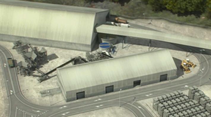
• Groups of crushing and screening Metso for reduction to gravels and sands.
• Two shredding groups LT300D and LT7150B, one mobile sieve ST 2.8 and one stationary CVB 202 and a sand treatment group.
The flowchart of this installation was, in summary, planned to be:
The feed was 0-100 of granitic rock. This 0-100 undergoes a cleaning process on a ST 2.8 screen, which took advantage of size 20-80mm. This 20-80 was reduced in closed circuit to 0-25mm by means of a cone crusher on tracks, LT330D.
To obtain an excellent coefficient of form, all sizes larger than 6 mm were processed in a vertical axis mill on LT7150B tracks. All 0-25mm already with excellent coefficient of form was classified in a stationary screen CVB 202 with washing to obtain gravel washed 12-25mm and 6-12mm. The resulting 0-6mm were taken to a hydro-cyclone sand treatment group, thickening tank, and filter press to achieve the quality.
All the material excavated by the TBMs was transported to the spoil shed via a complex conveyor belt system. These conveyors had different sections and belts widths depending on the demand for transport of the full excavation of the four TBMs. The capacity of the conveyors varied from 850 t/h to 2,000 t/h, belt widths from 1,000 mm to 1,200 mm, max. speed of the belt was 3m/s, and the installed power of the head end drive, booster drive and tail end drive went from 945 kW to 315 kW and 250 kW, respectively.
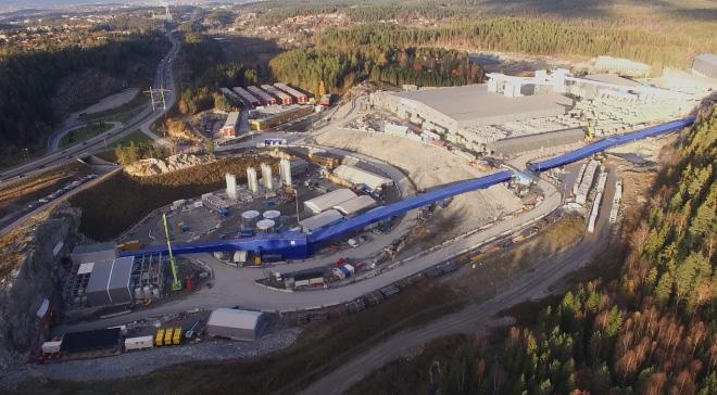
On TBM excavation methodology, it was needed to fill the gap between the external precast ring diameter and the TBM excavation one with mortar. On the Follo Line EPC TBM Project, AGJV choose a bi-component mortar solution. Basically, it was a combination of 2 elements: Component A was a colloidal suspension cement based, with other hydraulic conglomerates, and Component B was an accelerator (sodium silicate). The grouting plants chosen for the mixing and production of the bi-component consisted of two units.
Each Unit Plant consisted of:
• 1 Grout Mixer Unit (2 x 20 m³/h)
• 6 Vertical Monolithic Silos 85 m³
• 1 Agitator (2 x 6 m³ tanks)
• 1 Transfer Pump for A Component (2 x 20 m³/h)
• 1 Control Room for the 2 Mixing Plants.
• 4 Transfer Pumps for B Component
The auxiliary equipment in the plants handled:
• Mixing 2,5 m3, 2,000 l/min, 15 kW
• Silicate installations 8 containers of 25 m3 each
All the water pumped form the caverns to the surface was treated in one of two water treatment plants specifically designed to treat the kind of water that a construction project generates. The contract was very strict in terms of water discharges to the sewage network and water quality levels, so the robustness of the plant was critical. This is described in more detail in Chapter 8, “Dust- and water treatment”
The main characteristics of the each of the water treatment plants were:
• Total treatment capacity: 216 m3/h
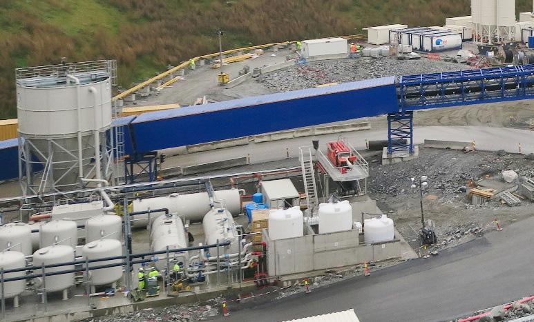
• Wastewater containing on average 15 g/l of TSS
• Power installation: 223 kW
• Effective working hours: 24
• Oil and grease limit: average 2,000 l/day
• pH-limit: 4 to 12
• Buffer and storage tanks for wastewater
• Automatic flocculent station
• Decanter cylinder tank FB7000V-WDR
The quality limits for the final discharge water were:
• pH-limit: 6.5 – 8.5
• Solids contents: 25 mg/l
• Oil and grease limit: not visible
Ventilation of the main tunnels and of the auxiliary tunnels was another very complex design solution, as the site configuration was more similar to a mining area in operation.
The final solution included main fans for the TBM tunnels and auxiliary jet fans for the other tunnels.
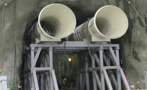
Main characteristics of the equipment installed:
• Main Fans: - Model: ZITRON ZVN 1-20/315-4 - Reversibility: Unidirectional - 4 units in the principal tunnels.
- Power: 315 kW - Diameter: 2000 mm - Flow: 68 m3/s
• Jet fans: - 24 units in total in the two adit tunnels. - Adit South 7 pairs - Adit North 5 pairs - Power: 41 kW
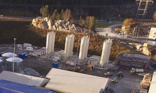
The fresh air was taken from the rig area and blown through the southern adit tunnel and distributed into the tunnel system from the southern cavern. The northern adit tunnel was used for the exhaust air.
Since the entire tunnel profiles of the southern adit tunnel were used as an air channel, did the cold air during winter time result in many iscycles, which had to be removed manually on a daily basis.
Good design in advance, smart ideas, previous experience, and lessons learnt from other similar projects that Acciona and Ghella had been involved in around the world, were the key factor for an achievement of a very compact, robust and 24/7 workable solution.
But as important as the design of the whole site, the logistic functionality of the day-to-day operations was another key element in this kind of continuous production sites.
The logistic team coordinated the daily internal and external deliveries on site, warehouse, workers’ shifts on barracks and their continuous rotation, among other activities.
The delivery to the TBMs of workers, materials and segments was one of the main activities. AGJV optimized the traffic in the tunnels by the way of using multiservice vehicles (MSVs) instead of the by client originally specified transport by railway. These special transport vehicles allowed to have both ways of traffic into the TBM tunnels with no interruption, as the MSVs were narrower than standard vehicles.
Different types of such special vehicles were procured on the project: men rider (allowed to transport 28 people), segment vehicles (2 complete precast rings could be delivered at the same time) and special platforms for rescue chambers, materials, ventilation, etc.
Main characteristics of those vehicles:
• MSVs for rings: - 5 units
- Model: MSV 130-4-1900 - Power: 405 KW
- Service: Each vehicle carried two complete rings
- Quadruple Multiservice Vehicle, 8*18*18 - Turning radius: 15 m. - Dimensions: 2100 x 3306 x 43,615 mm - Weight unloaded: 48,000 kg - Max vehicle weight: 172,000 kg - Max speed with load on flat ground = 17 km/h
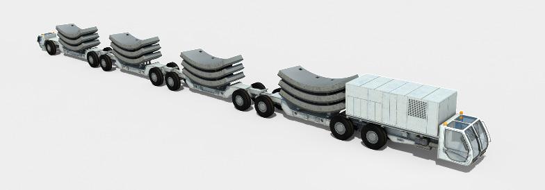
- Max speed with load in maximum slope (10%) = 10 km/h
• MSVs for auxiliary - 11 units
- Power: 245 kw - Weight unloaded: 17.000 kg - Max capacity(payload): 21 ton - Crew transport 5 units. 21.x1.981x3.940 mm 18.000 kg - Rescue chamber 4 units. 24.198x1.981x3.940 mm. 18.500 kg - Duct cassette ventilation 2 unit. 23.894x1.981x3.940mm. 18.500 kg
Figure 12-16: Segment MSV – 3D design.
For the excavation of the 36 km of TBM tunnels, Acciona Ghella Joint Venture procured four brand new double-shell tunnel boring machines (TBMs) from Herrenknecht. The main characteristics of the TBMs were (reference is also made to Chapter 10 “Tailor made TBMs for boring in hard rock at the Follo Line project”):
• Adapted to high rock strength. Bane NOR input based on Norwegian experience
• 71 Cutter rings 19” on 71 tracks
• Heavy structure, stiff support
• Diameter machine/internal tunnel diameter: 9.96 m/8.75m
• Length of machines: 150 m
• Weight: 2,400 tons
• Installed Power: 6,200 kW.
• Main bearing size increased form 6.0 m to ø 6.6 m
The TBMs were designed, manufactured, pre-assembled and commissioned in Herrenknecht facilities at Schwanau, Germany, previously to their transport to
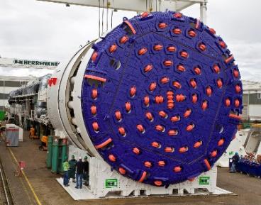
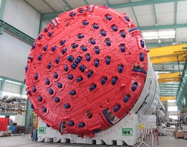
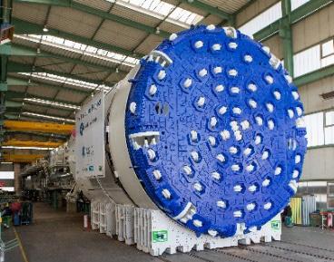
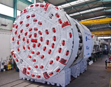
the job site. This works took one year for the 4 TBMs (the contract signature with Herrenknecht took place the 15th of March 2015).
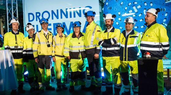
The TBMs 1 and 2, which excavated in the northern direction, from the northern assembly cavern, towards Oslo started excavation in September and October 2016.
The breakthrough of both TBMs heading in the northward direction, took place the 11th of September 2018, just 2 years after start-up of the first machine. The machines had then excavated approximately 9 km each, including pre-grouting in areas where leakages occurred. More details about handling of water leakages are given in Chapter 14 “Geological mapping and follow-up during the TBM excavation” and in Chapter 15 “Groundwater control and monitoring”.
Figure 12-19:
breakthrough in the north, where the two machines arrived into two parallel caverns.
The TBMs 3 and 4, which excavated approximately 9 km each in the southern direction, from the southern assembly cavern towards Ski, started excavation on November and December 2016 and achieved both breakthrough the 26th of February 2019. They had
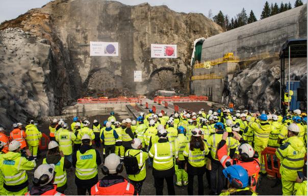
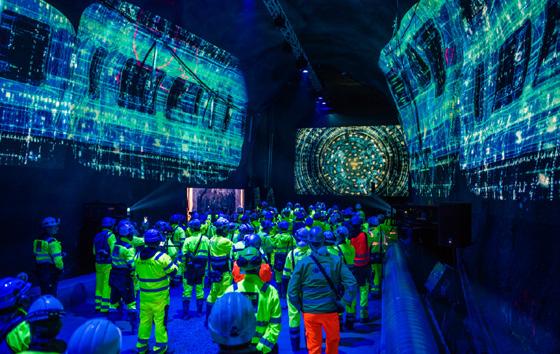
12-20:
also performed several rounds of pre-grouting in areas with fracture zones, where leakages occurred.
In the table below the main TBM production excavation rates achieved are summarized:
Table 12-1: Summary of the TBMs performance.
The previous figures must be analysed into the following context:
• Almost 8.000 m tunnel were pre-grouted from the TBMs during the excavation of the tunnels.
• Pre-grouting affected normal TBM excavation, as no tunnel excavation was possible during this activity.
Considered this factor, AGJV managed to achieve the expected TBM production rates (between 14 and 15 m a day). All four TBMs started excavation ahead of the contractual schedule, and the large precast factory at the site started production according to the plan, the excavation of the TBM-tunnels finished according to plan.
Cross passages were excavated between the two TBM-tunnels every 480 – 500 meters. The main purpose of this cross passages is for evacuation, but electrotechnical installations are also installed in all the 54 cross passages along the tunnel. Details regarding the evacuation concept is described in chapter 19 “Safety concept for the operational phase”
The design of the cross passages opening was optimized by 2D and 3D analysis to a uniform width along the tunnel alignment, the final opening width is 3.8m. The design of the opening foresaw some assumptions to be verified during construction.
Among other design loads as weight of the segments, wedge failure and variable loads, the main assumptions for the 3D verification of the segmental lining on the acting water pressure after opening of the TBM segments were the following:
• A residual direct water pressure of 1 bar on the opposite side of the opening and atmospheric pressure on the opening side at ring -1, 0 and +1.
• A uniform residual direct water pressure of 1 bar at the boundaries of the 3D model (±5 rings).
• A linearly interpolated residual direct water pressure for all other rings of the model.
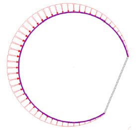
• A uniform indirect water pressure of 3 bar on rings ±3 to ±5.
• A uniform indirect water pressure of 3 bar on approximately 190° opposite the Cross Passage opening for rings from -2 to +2.
• Atmospheric pressure at the opening and indirect water pressure gradually increasing to 3 bar in rings -1 to +1
• Indirect water pressure linearly interpolated between 0 and 3 bar on the remaining section of the lining.
For final states, an overall non-uniform direct water pressure was applied with a maximum of 11 bars at the opposite side of the opening, with atmospheric pressure on the opening side (see figure 13-2).
Figure 13-1: Water pressure distribution at opening (direct and indirect).
Figure 13-2: Water pressures around the tunnel in final states from hydraulic analyses.
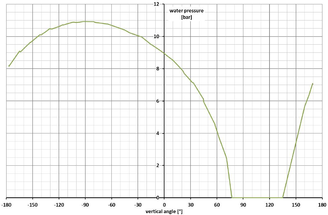
As a result of the 3D model final analysis, the TBM segments at the cross passages (rings -1, 0 and +1) have been designed with additional reinforcement (total of 148.7 kg/m3 compared with a normal 40.7 kg/m3) and 20 kg/m3 of steel fibres B65/35.
Special shear connectors between ring -1 and 0 and between ring 0 and +1 have been specified for these segments.
Figure 13-3: Opening design with additional shear connectors.
Each cone shear connector can resist to 400kN of shear force.
Figure 13-4: Shear cone for Cross Passages openings.
Figure 13-5: Shear force-displacement curve for Bi-block connectors.
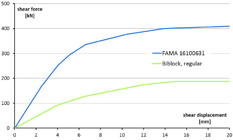
The design of the openings for the TBM Follobanen cross passages has been focused in avoiding additional unnecessary time consuming works for segment support before the cutting of the latter. The success of the design brought the construction team to significant time saving when starting cross passages excavation works.
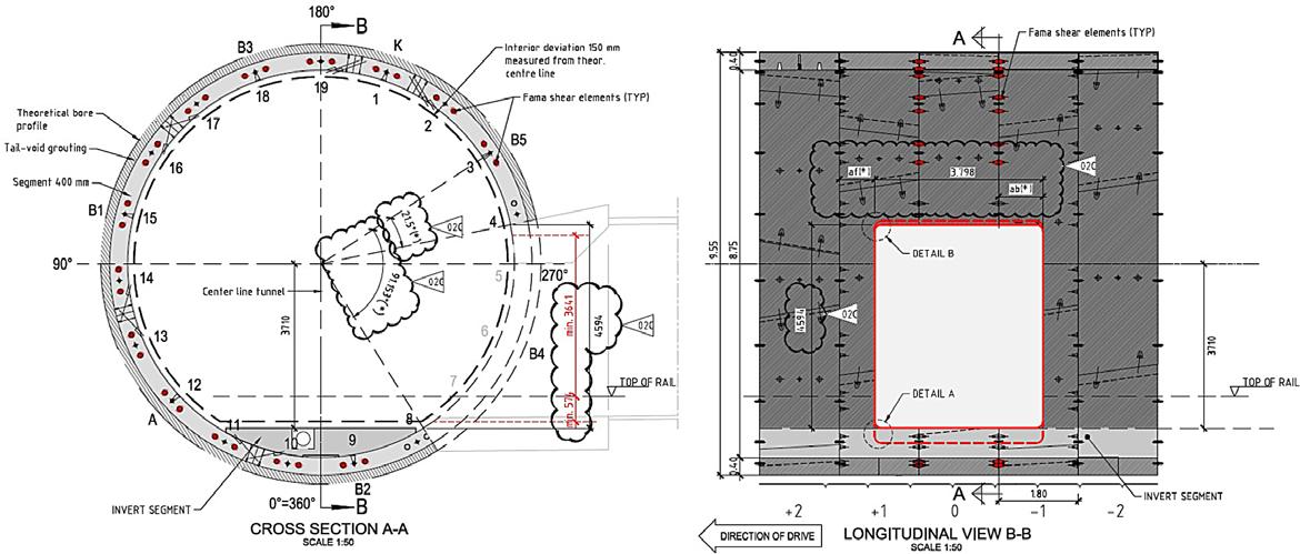
Before the actual opening of the segments works could start, some measures and mitigations had to be performed:
1. To confirm the design assumptions, pressure measurements were done at ring 0.
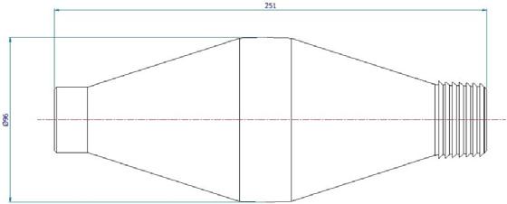
2. To avoid lowering of the groundwater table during the excavation works of the cross passage, probe holes and possible pre-grouting works had to be performed.
3. To avoid water running behind the lining, along the tunnel to enter into the cross passage when opening, various grouting activities behind the segmental lining had to be performed in advance.
To confirm the design assumptions, manometers were installed in both the opening side and opposite
the opening as shown in figure 9a-23. Manometers were normally installed from the back up of the TBM drilling to the rock profile.
Figure 13-6: Manometer locations at ring 0 before opening of Cross Passage.
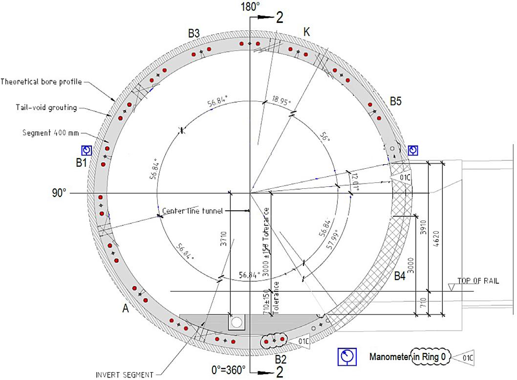
When the pressure measured in any of the manometers was less than 3bar, no treatment was required. When the pressure in any of the manometer was above the 3bar, post grouting treatment of the rock mass or lowering the pressure behind the segmental lining (both on the opening side and opposite side) was foreseen. When the case of opening the grout ports to lower the pressure behind the segmental lining, ground water level was always monitored through the piezometers system installed from the surface. Lowering of the pressure behind the lining
had to be performed in a uniform way (all the grout ports were opened). Water flow was also measured.
Water flow in the rock mass
Before the opening of the cross passages and to avoid lowering of the ground water table during excavation and final state (cross passages of the Follobanen project are designed as a drained solution), probe holes had to be drilled in the cross section of the opening. Depending on the location of the cross passage, the water ingress limits were set as shown in table 13-1.
Table 13-1: Limit values for leakage in probe and control hole.
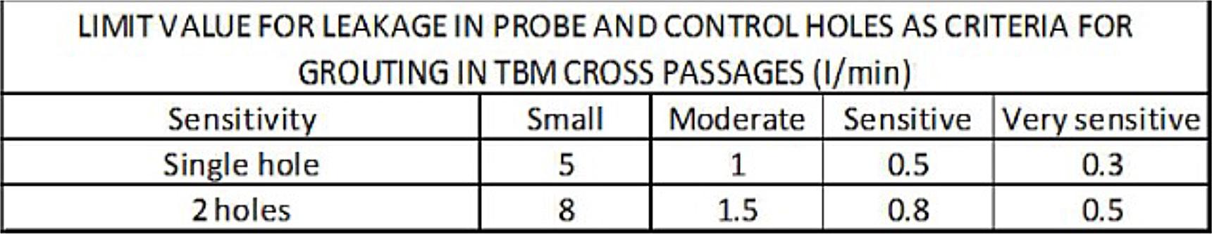
When the measured leakages in the probe holes exceeded the limit values of table 13-1, pre-grouting of the rock mass was performed. Typical drilling pattern of a pre-grouting round from the TBM tun-
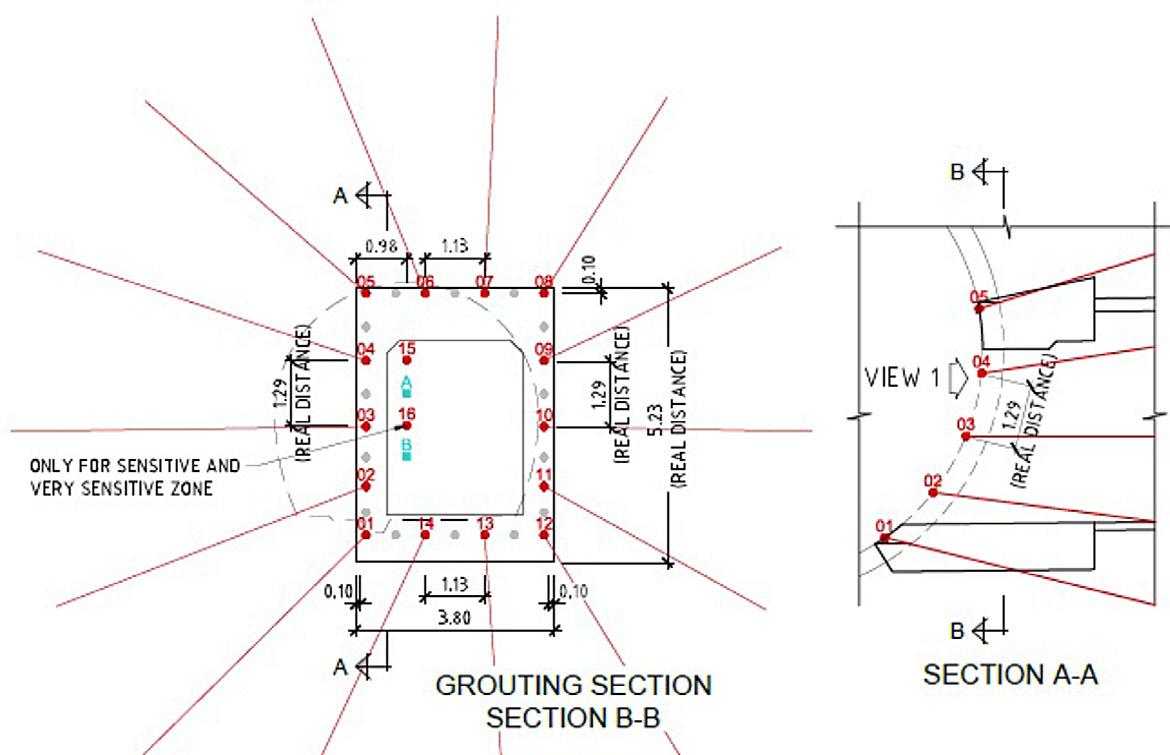
nel can be seen in figure 13-7. Drill holes were drilled before opening of the cross passage. The packers, to allow pre-grouting injections at 40bar were placed 2m from the TBM segmental lining.
Additional probe holes were drilled when possible fracture zones were encountered according to TBM excavation data.
Additional measures before opening of the segment rings
Before cutting of the segments, additional measures were undertaken to limit the water ingress from water running along the tunnel between the segmental lining and the rock mass. These measures can be summarized as:
1. Contact grouting of the backfilling gap from ring -10 to ring +10.
2. Polyurethane (PU) rings at ring -5 and ring +5, with a distance between the holes of 700mm around the cross passage opening.
3. Control holes inside the opening drilled, and water ingress measured.
4. If water ingress exceeded 10 l/min, additional cementitious contact grouting between the PU rings were performed.
During the excavation, pre-grouting from the TBMs in the areas where cross passages should be located, was identified to be the most effective method in order to reduce the leakages for the later opening of the cross passages. When this routine was established, pre-excavation grouting from the TBMs were usually performed with two umbrellas on each side of the opening area.
The geometry of the opening of the TBM tunnel
Cross passage had been reduced to a minimum to avoid additional works to support the TBM segments until the collar was built. The opening is 3.8m width by 4.64 m height.
The TBM tunnel cross passages at the Follo Line project can be subdivided into two categories:
• Cross passages between the TBM tunnels
• Cross passages between the TBM tunnels and the escape tunnel
For openings of cross passage between the TBM tunnels, the segments were cut with a diamond saw. Close to the lining, the rock was excavated by using the drill and split methodology. The length of these cross passages were normally approximately
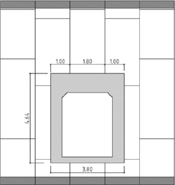
25 meters. For excavating the central part of these cross passages, careful blasting, within strict limits, was performed. For the last part of excavation towards the lining of the other tunnel, drill and split were used again. Finally, the lining of the other tunnel was opened by diamond sawing.
As a part of the excavation sequence in the cross passages, probe drilling was performed before the drill and split and before the careful blasting. If leakages from the probe holes exceeded the identified trigger values, pre-grouting was performed to limit the water leakages and avoid drop of the porepressure, lowering of the groundwater table and development of settlements on buildings and structures on the surface. Even though the cross passages were built as drained solutions, mitigations were required in order to limit the leakages and maintain the water balance in the sediments above the tunnel.
The opening of the cross passages between the TBM tunnels and the escape tunnel was characterized by different procedures, depending if the TBM tunnel pipes and TBM tunnel conveyors were on the opening side. When this was the case, and due to safety regulations, a 1st stage opening of 1.7m by 3.8m above the TBM pipes had to be performed.
Figure 13-8: Geometry of the TBM tunnel cross passages opening.
Figure 13-9: Provisional small opening for escape tunnel cross passages with pipes.
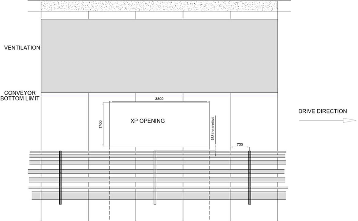
This openings from the escape tunnel were performed with wire cutting technique.
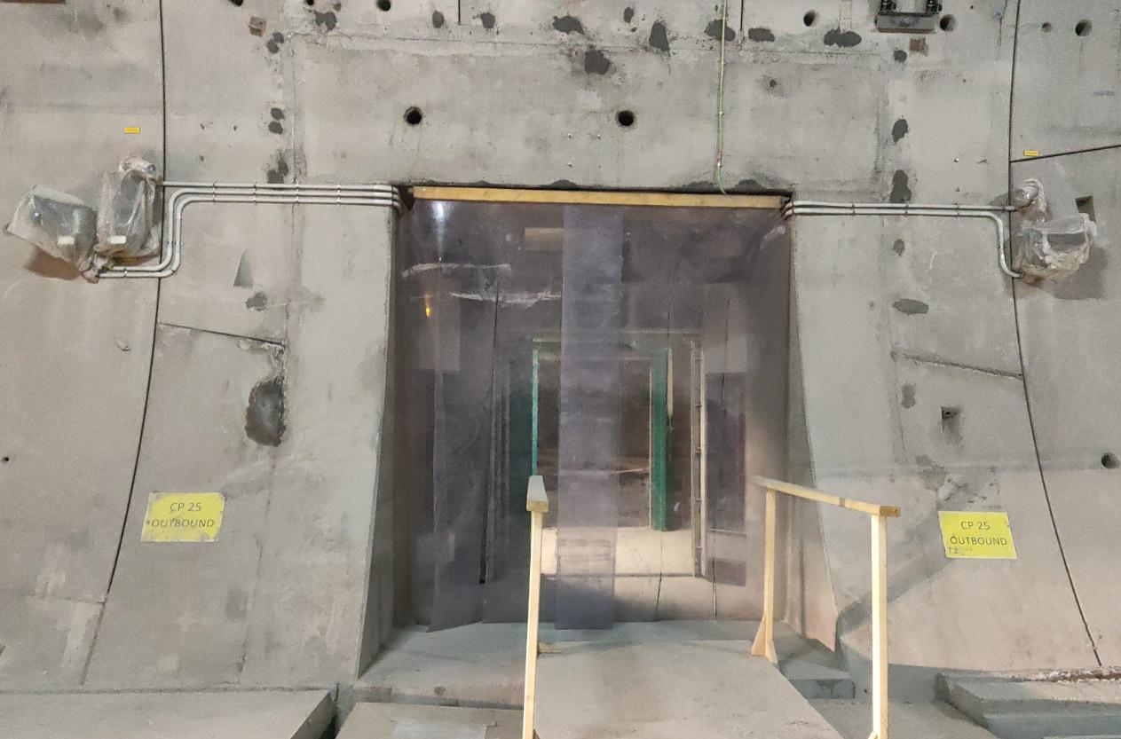
The opening of the cross passages were performed approximately 300 – 500 meter behind the TBMs.
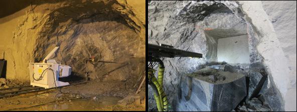
As an important supplement to the geological mapping, that had been performed before the start-up of the TBM excavation, systematic geological mapping was daily executed in parallel with the maintenancestop during the entire excavation period, in order to document the real geological conditions along the tunnel section.
The challenge related to geological mapping in a double shield TBM-project is the restricted access to the tunnel face and the rock mass. Behind the shield, the segmental lining is installed, making the bedrock inaccessible for mapping behind the machine. The only area the rock face is available, is in front of the TBM, through the cutter head via the Ø60cm manholes. This makes geological mapping only possible when the machine comes to a standstill and depending on how far the cutterhead is retracted, the view can be very limited. Performing strike and dip measurements at the tunnel face is challenging as a normal geological compass is useless on a TBM due to the magnetism. In the Follo Line project, there was a need for alternative sources of information that could give additional information and create a more complete and detailed impression.
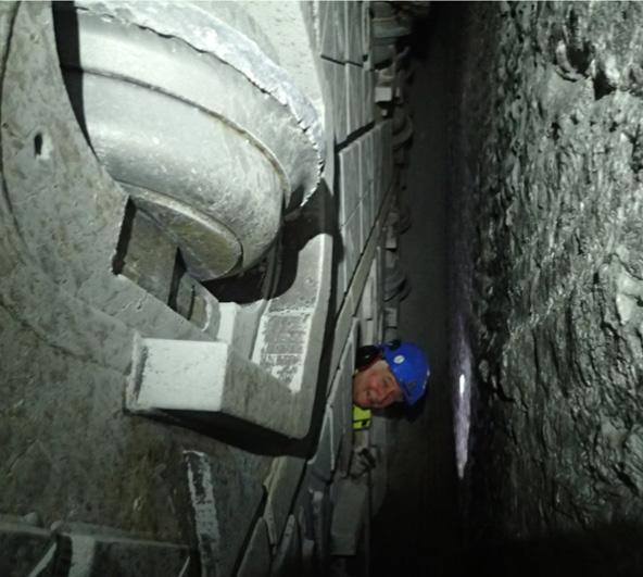
NTNU-model used as a compensation
The geological parameters mapped were determining the contractors right to compensation according to the NTNU model.
The NTNU hard rock tunnel boring model was part of the contract and the intention was to use it as a compensation model for the EPC TBM. The model covers the complete tunnel boring process; from the early planning stage, through pre-investigations, time and cost estimates, tunnel excavation and finally acquisition and interpretation of experience data. The estimation model is based on job site studies and statistics from tunnelling in Norway and abroad (Bruland, 1998).
Rock mass fracturing is the most important for the penetration rate parameter. In the NTNU model the rock mass fracturing is expressed by the fracturing factor (ks). ks is dependent on the degree of fracturing (type and spacing) and the angle between the tunnel axis and the planes of weakness, α, (1). The orientation of the fracture-planes is determined from measurements of strike and dip.
(1)
where αs= strike angle, αf = dip angle and αt= tunnel direction
For more than one set of fracture-planes, the total fracturing factor ks-tot is as follows:
(2) where ks-tot = total fracturing factor, ksi = fracturing factor for set no. i and n = number of fracturing sets.
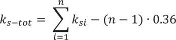
The fracturing factor is shown in figure 14-2 below, as a function of fissure or joint class and angle between the tunnel axis and the planes of fractures.
The compensation for geological conditions was related to variation in the kekv.
In the rock mass present in the project area the porosity is <2%. This give a kpor =1. The DRI was found in laboratory tests, and samples were taken regularly. The geological mapping was therefore focused on documenting the rock mass total fracturing factor, ks-tot. According to the NTNU model one need to document number of fracture sets, strike and dip of the fracture sets and the fracture spacing of each set.
Probe drilling for detecting water ahead of the TBM and to prepare for systematic and continuous mapping by optical tele-viewing along the tunnel alignment, was performed every day during the maintenance shift. (Lawton, Gammelsæter, Finnøy, Syversen, 2018). The detection of water is described below.
Figure 14-2: Fracture classes representing fracture spacing and angle, given a ks for each fracture set. Also, the correction factor for DRI is shown (Bruland, 1998).
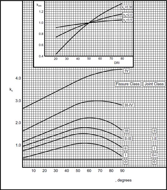
The rock mass properties for TBM boring are expressed by the equivalent fracturing factor, kekv.
(3)
The results from the continuous fracture mapping by optical tele-viewing (OTV) was used as input for the NTNU model for compensation. This model is based on continuous fracture mapping from an open TBM, where the rock-surface is available behind the cutterhead. (Bruland, 1998). For a shield-TBM, the rock-face is only visible through the cutterhead when the TBM is not excavating. To collect necessary and continuous information about the different fractures- and fissure systems along the entire tunnel section, 40 meters long probe-holes were drilled from behind the shield, forward ahead of the machines. An overlap of approximately 10 meters between the lengths were normally achieved.
Where ks-tot= total fracturing factor
kDRI= correction factor for DRI
kpor= correction factor for porosity of the rock.
The probe-holes were logged with Measure While Drilling (MWD), but this gave mainly information about fracture-zones and presence of water, and no precise information of the orientation or condition of the fractures. The MWD-data was therefore not suited for detailed fracture-mapping as required for the NTNU-model.
Figure 14-3: Overlapping probe-drilling for double shield TBM.
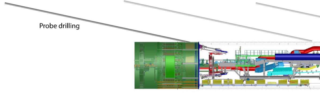
Instead, mapping of the probe-holes by an optical tele-viewer gave pictures with quite high-resolution scale, where fractures and their orientation could be mapped in detail. An example is shown in figure 14-4 below.
Open fractures were usually easy to detect, while closed fractures or fractures with small aperture could be difficult to observe in the picture. Sometimes a line of brownish colour from weathering could reveal the presence of a fracture that was otherwise undetectable in the picture. Also fractures in dark rock like amphibolite could be difficult to spot. Fractures and fracture-planes that were believed to contribute to the rock breaking process under TBM boring were marked on the picture with special software. With the same software, it was then possible to decide strike and dip of these structures. These data were then used to estimate fracture sets and fracture spacing. Further on, ks could be estimated. The project estimated one ks value for each probe hole.
The probe-holes prepared for OTV were bored upwards to achieve a drained hole. They were also flushed to avoid debris covering parts of the holes. (Kalager, Gammelsæter, 2019)
The OTV-logging provided a continuous geological data record along the entire tunnel section. The instrument for televiewing had a compass to keep track of borehole orientation. The result was a highresolution picture where fractures and lithology could be mapped in detail and of good enough quality to be used as input for the NTNU-model.

Due to influence of all the metal parts from the TBM, including back-up to the compass, corrections of dip and strike direction had to be done afterwards.
The continuous OTV-logging provided a huge amount of information to be analysed. To utilize all the data collected from the OTV, it was important that the analysis were performed by geologists with experiences from face-mapping and chip analysis as well.
The purpose of performing face mapping was to gather general geological information and to get input to assess the fracture factor Ks, which was part of the compensation model. Mapping was performed every morning during the maintenance shift by geologists from both the client and the contractor. Both parties signed the agreed mapping form before leaving the TBM.
Depending on the daily excavation rate, there were 15-20 tunnel meters in average between each face mapping.
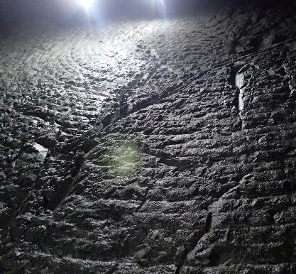
Access to observe the face was through the manhole and to a certain degree through muck openings as well. The cutter-head was retracted from the face to make it possible to get an overview of a larger part of the face.
The geological mapping of the face gave information about presence of rock types and eventually of hard and abrasive minerals like quarts or garnet. Signs of weathering were often visible. Other important information was the number of fracture-sets visible and the space between the fractures. In some cases, the mapping made it possible to observe the roughness of the fracture planes and eventually infilling or aperture. It was also possible to verify if fractures or fracture-planes contributed to fall-out or over-break. Water seepage from the face could also be identified. Figure 14-5 shows an example of how photographing of the face contributed to supplement the geological mapping.
Figure 14-4: OTV image with fractures mapped.
Figure 14-5: Fractures with different orientation identified at the face.
3D-Photographing at face
3D-photographing of the face was done regularly every day during the maintenance shift. Equipment and software from 3GSM were used. A camera was mounted in the manhole of the cutterhead, and a circular video was captured during one rotation of the cutterhead.
Advanced software generated scaled and oriented 3D images from measurements taken. This is illustrated in figure 14-6 below.
size could give tendencies on the efficiency of the boring process.
Every 250 meter of the tunnel excavation, core drilling was performed at the front of the TBM’s. Cores of four meters length were drilled perpendicular to the tunnel to get rock material for laboratory testing to determine Drilling Rate Index (DRI), Cutter Life Index (CLI) and mineral analysis. The DRI value was needed to be able to calculate the Kekv as an input for the NTNU-model. For cutter life calculations, CLI and the mineral content, mainly quartz, was needed.
In addition, two meters long cores were bored for geological logging as a supplement to the geological information obtained from the daily tele-viewing, face mapping and chip analyses.
All the mapping needed for using the model were performed by both the contractor and the client. The fact that some of the data for the model was based on subjective interpretations by the parties, resulted in different views of a potential compensation for deviation of the ground conditions. Even though the parties had a disagreement about the size of the compensation, the results provided a basis for a final compensation related to changes in the ground conditions.
Figure 14-6: A 3GSM-photo gave a ”doughnut”-shaped picture where fracture-sets were visible.
The width of the doughnut shaped picture was in the range of 0,5-1,5 meter depending on how far back the cutterhead was retracted. The result was a documentation of the rock mass conditions on that particular tunnel-face. From the 3D images, it was possible to identify and measure over-breaks, perform geological mapping and to analyse fracture set orientation and to some degree fracture spacing as well.
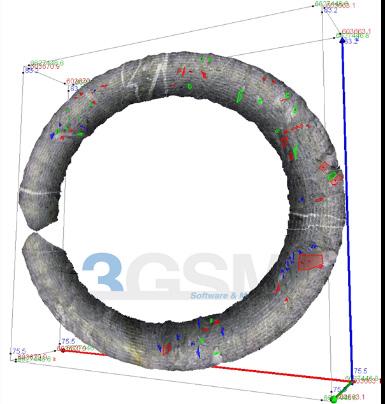
Chip analysis can be a valuable tool to obtain information on the rock breaking process and was therefore performed regularly. Normally 10-20 of the largest chips were collected from the TBM excavation and measured in three directions, x, y and z. The shape and size of the chip gave information or tendencies on fracturing factor, rock brittleness and hardness. The combination of chip shape and chip
The different methods for geological mapping are listed in table 14-1 below
A network of registration wells for measuring the pore-pressure along the tunnel section and in sensitive areas connected to the tunnel by fracture-zones were installed before the start-up of the tunnelexcavation. The first piezometers were installed in 2009, almost seven years before the start-up of the TBMs. Early installation of monitoring is important to obtain a history of natural seasonal variations in the pore pressure. (Syversen, Lawton, Finnøy, Gammelsæter, 2018). The wells and piezometers for the groundwater monitoring system were installed in the rock, with connection to fractures, and in the soil, that mostly consists of marine clay, as well.
The monitoring of the pore-pressure was a continuous and ongoing process throughout the project, and after finalization of the excavation until the water-balance was stabilized as well. All sensors
were logged automatically every 10th minute, and the results were uploaded to a web-based GIS portal with a frequency of down to1 hour if deemed necessary.
Face mapping
Photogrammetry from face
Probe drilling
In addition to the pore-pressure monitoring program, an extensive settlement monitoring program was carried out. Nails were mounted on the foundation of more than 2300 buildings. The nails were
Inspection of the rock through holes in the cutterhead.
3D Photographing of the face by the use of several georeferenced photos.
Two drill rigs on each machine. 38 possible drill positions in the shield. Holes were drilled with an angle of 11 degrees.
Optical televiewer 2D photography of the probe holes. Gives an oriented projected photography of the inside of the borehole.
Core drilling
Two cores of 2-meter length were taken. One perpendicular to the tunnel axis, and one parallel.
One core of 4-meter length was taken perpendicular to the tunnel axis.
Lab testing 1 meter out of the 4 m long core was taken to perform the following tests:
• Drilling Rate Index
• Cutter Life Index
• Quartz content
• XRD
Chips-analysis
Samples were taken from the conveyor belt and studied.
Daily on all machines. Were performed during maintenance stops.
Daily an all machines. Performed during maintenance stops.
Continuous and overlapping probe holes. The frequency was dependent on the production, but it was usually performed every day.
Was performed on overlapping probe-holes so that every meter of the tunnel was mapped.
Fracturing, rock type, water leakages etc.
Fracturing, rock-types leakages etc. Can generate stereo-nets and rose diagrams from each face.
Water leakage. All holes were also logged by MWD.
Fracture-data, like orientation and distance between fractures. Lithology in the hole.
Every 50 meters
Every 250 meters.
Fracture mapping and lithology. Fracture mapping and lab testing
Every 250 meters.
DRI, CLI, quartz content and XRD. The results were used as input in the compensation model which regulated compensation for changes in geological conditions.
Occasionally
Was used to get a better understanding of the breaking process
Table 14-1: Different methods used for geological mapping from the four double-shield TBMs.
manually surveyed in due time prior to passing with the TBMs and after the TBMs had passed, and the readings were uploaded to a web portal. In addition to the manually measurement of settlements, a monitoring program utilizing satellite data (inSAR) from 2014 and up to date was established to identify if settlements occurred on buildings along the tunnel section. How the pore-pressure, ground-water levels and development of settlements were followed up, is described in more details in Chapter 15 “Ground-water control and monitoring”
To fulfil the requirements regarding limited drop of pore-pressure and no damages to buildings or other infrastructure in the areas above or close to the tunnel, the tunnels were built as an undrained tunnel solution. Concrete segments with watertight gaskets were installed right behind the shield of the machine. The concept was based on a solution that as soon as the lining was installed, the backfill behind the lining should be completed, and the grout-ports should be closed. Then the tunnel should become water-tight and acts as an undrained tunnel. This is described in more details in Chapter 16 “Production and installation of the segmental lining”
The leakages occurred in areas with fractures. (Kalager, Gammelsæter, 2019). The rock-mass itself was solid and impermeable. Before the lining was installed, there was an open rock-face of approximately 15 – 20 meters between the tunnel face and the last installed segmental ring. In a few areas where highly permeable fracture zones intersected the tunnel, there were some extensive leakages into the tunnel before the lining was installed. Such leakages followed the network of fracture zones, and in the worst case, a huge area up to 1.5 km from the tunnel was seen to be affected. Specific experience of this is also described in more details in Chapter 15, “Groundwater control and monitoring”.
The experience achieved in areas with such leakages through fracture zones, was that the water ingress also resulted in outwash of the cement-based backfill that was injected behind the lining. This outwash made it possible for more water to flow behind the lining, which resulted in even more out-wash of material and in some cases a destabilizing of the lining as well. From an early stage of the excavation period, it was obvious that the contractor needed to improve their strategy and methods for handling the water as an integrated part of their construction.
Daily, during the maintenance-shift, probe-drilling was performed in the rock ahead of the TBM to register the geological conditions, detect fractures with high permeability and identify if leakages could be expected. The number of probe holes depended on the sensitivity of the area above the tunnel and the expected geological conditions ahead of the TBM.
The entire tunnel section was classified in different sensitivity-zones defined as small sensitive, moderate sensitive, sensitive and very sensitive. In general, one probe hole located on the top of the cutterhead or two probe holes in different locations related to the cutterhead were bored in areas defined as small sensitive. In moderate to sensitive areas, experience showed that increasing the number of probe holes to four distributed in different positions around the cutterhead, gave quite reliable information about the geological conditions ahead of the TBM. In very sensitive areas the number of probe holes were set to six.
To reduce the amount of leakage before the lining was installed, pre-grouting was performed from the TBMs when identified as necessary, based on water ingress measurements from the systematic probe drillings. The trigger values of water leakage from the probe holes were based on the sensitivity class of the areas affected by the tunnel excavation. Based
Figure 14-7: The tunnel crossed different networks of fractures. The rings show the crossing-points between the tunnel and identified main fractures and the stars illustrates the affected areas along the different fractures within the network. Blue and red rings indicate crossing of fractures within different networks.
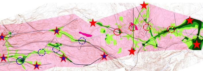
Figure 14-8: A 3D-visualization of the tunnels crossing the different main fracture-zones. The blue and purple colours illustrate high penetration-rate, which correlates with the fracture-zones identified before the start-up of the TBMs.
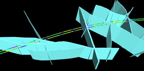
on experience achieved during the excavation, the trigger values for starting pre-grouting in the different sensitivity areas were set to 80 l/min from one probe hole in areas with small sensitivity, 40 l/ min from minimum two probe holes in moderate to sensitive areas. During the excavation, the number of probe-holes were in some cases increased to six, and the trigger-value for starting pre-grouting redused to 25 l/min in total from all the probe-holes. In very or highly sensitive areas, 8 l/min in total from all the six probe holes were used as trigger-value for starting pre-grouting.
In some of the areas classified as high-sensitive, mandatory pre-grouting was required.
Each TBM was equiped with two rock-drills for probing and for drilling the holes that should form the umbrella for pre-grouting. The double-shell machines were designed with 38 holes around the shell where it was possible to perform holes for probing and grouting.
Every 500 meters, the two parallel tunnels are connected by cross-passages. The experience showed that opening of this cross-passages resulted in additional leakages. Even though pre-grouting was done as an umbrella from the tunnel around the portal of the cross-passage, leakages after opening-up the lining occurred. The water seemed to come through channels in the backfill material between the lining and the rock. After considering different methods to stop the water in this portal-area for the crosspassages, contact-grouting, with low pressure, of the backfill area around the opening was identified
to give the best result.
In areas defined as very sensitive, it was decided to do systematic pre-grouting from the TBM in the areas around the future portals for the crosspassages as well as contact grouting.
This methodology for identifying water and limit the leakage was developed and improved during the excavation phase, and the results appear to be positive. The drop of the pore-pressures stopped and were re-established when the performance of grouting was tailor-made to the geological conditions. The principles for controlling the water balance during the excavation is illustrated in figure 14-9 below. It is also described in more details in Chapter 15 “Groundwater control and monitoring”.
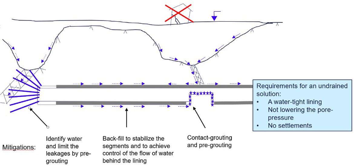
To compensate for the water leaking into the tunnel, and by that avoid a drop of the pore-pressure and development of settlements on buildings within the influence area of the tunnel, temporary infiltration wells were installed at different locations. The wells were operated from the surface.
Many of the wells were operated with good results, but not all of them. The key to success seemed to depend on the quality of the installation and the match with the geological conditions. The infiltration wells were usually drilled 20-50 m into the rock. The intention was that they should cross identified permeable fracture zones. These fracture zones were preferably inclined under soil deposits.
Water with some overpressure was infiltrated from the rock well trough the fracture zone up into the soil. Pressure and flow were carefully controlled to avoid piping effects and out-wash in the soil. The infiltration of water was mostly activated in combination with pre-grouting to control the water balance in the area affected by the tunnel excavation.
It was a requirement that these infiltration wells should only be used as a temporary mitigation to maintain the pore-pressure while the TBM passed by. After the lining was installed, there should be no need for them anymore.
Most of the tunnel excavation in the Norwegian hard rock has traditionally been performed by drill and blast methodology. Therefore, a decision to use TBMs to excavate the main part of the 20 km long twin-tube tunnel at the Follo Line project caused a certain degree of scepticism.
Lessons learned from the excavation of this tunnel section by four double-shell TBMs is that there are some key-factors that must be present for achieving a successful result, namely establishing a good knowledge of the geological conditions along the tunnel section, systematic mapping of the conditions ahead of the TBMs during the excavation, systematic measurement of the pore-pressures and settlements, improved and tailor-made mitigations to limit the amount of leakages and timely and appropriate decision-making for activating the mitigations.
The machines and the equipment must be tailormade for the specific ground conditions. Last, but not least, the experience and skills of the personnel, on both the contractor’s and the client’s side, and the communication and co-operation between them, is also in many ways crucial for achieving a good result.
The experience from the excavation of the two Follo Line tunnels is that the contractor improved their skills for handling water leakages during the excavation. Nearly 8.000 meters of pre-grouting were performed. Their procedures and performance for probe-drilling, detection of water and pre-grouting became more efficient after a while, and in total, the excavation must be defined as being a success.
Bruland, A. 1998. Hard rock tunnel boring. Doctoral thesis 1998:81. NTNU
Fritzøe Lawton, M. & Gammelsæter, B. & Hoff Finnøy, A. & Syversen, F. 2018. Continuous mapping with OTV from hard rock double shield TBM as input for compensation. WTC2018, Dubai
Kalager, AK. & Gammelsæter, B. Did the selection of TBMs for the Follo Line project tunnels satisfy the expectations? WTC2019, Napoli
Syversen, F. & Lawton, M. & Hoff Finnøy, A. & Gammelsæter, B. 2018. Water ingress and groundwater control in double shield TBMs at the Follo Line project – Norway. WTC2018, Dubai
The paper covers relevant aspects of ground water control and monitoring of the Follo Line project. Based on the geological and hydrogeological ground characterisation, the contract requirements for water tightness and strategy for ground water control are described. During project execution it became obvious that the measures for dealing with water ingress had to be improved significantly. The final concept included several probe drills depending on the sensitivity of the area with rather strict water leakage limits for pre-excavation grouting, resulting in many pre-excavation grouting rounds.
Many tunnel projects must consider the risk of highwater ingress during the construction phase, resulting in pore pressure reduction in both rock and soil above the tunnel. In Norway, the risk of settlements in sensitive/ marine clay sediments and draining wetlands is particularly high. It follows that it is crucial to identify areas sensitive to pore pressure reduction above the tunnel alignment during the design phase. The reason for this is that the isostatic uplift after the last ice age and settlement in sensitive marine clays are often located in rock surface depressions. Infrastructure and buildings constructed on top of these sediments are therefore exposed to the risk of pore pressure reduction resulting in settlements during tunnel excavation. Avoiding any kind of damage to vulnerable vegetation above the tunnel alignment is also important.
The rocks in the Follo Line project area consist predominantly of Precambrian gneisses. A significant number of intrusives from the Perm period, as well as amphibolite dykes/sills occur. The amphibolite dykes/sills are more prevalent in the project area than the Permian intrusives. Most dykes/sills are a few metres thick, with a small proportion thicker than 10 m. Sedimentary shale occurs in a very short part in the North towards Oslo Central Station.
The Precambrian gneisses are folded in sharp isoclinal folds and they expose a clear foliation. The dominant rock structure in the project area strikes N-S to NW-SE. Farthest south towards Ski, the structure turns over to an E-W orientation. Fractured layers in the gneiss have been exposed to erosion due to mineral composition (high mica or amphibole con-
tent), often in combination with fault offsets which have resulted in long, prominent ridges and valleys. Several groups of fracture zones strike across the structure of the gneiss.
The average joint spacing for the various joint sets observed at the surface does not seem to be influenced by the proximity to the fault zones. One reason for this may be that some rock exposures are small, making it difficult to determine the general joint spacing. Another reason may be that random joints are not included in the average joint spacing, as these joints do not belong to any joint set. A third reason is that areas most strongly influenced by the fault zones usually form soil covered depressions in the terrain and therefore do not show rock exposures at the surface.
The superficial deposits in the project area are mainly of marine origin. Normally there is also a moraine layer on the rock surface. In addition, some limited areas are covered by organic deposits (peat/ bog). Fundamentally, marine- and organic deposits are settlement sensitive. Whether or not settlements will occur, as a result of groundwater lowering, depends on several conditions. In particular type of deposit, properties, horizontal extension, and ground water level.
Groundwater is primarily restricted to fissures-, fractures- and fault zones in the basement rocks. In some few areas restricted groundwater aquifers can be found in the overburden along the alignment especially along rivers, streams, and bogs.
Hydraulic conductivity measurements have not been conducted in the overburden. Hence neither the hydraulic conductivity (permeability) nor the porosity of the overburden in the project area is known in detail. The effective porosity of clay is seldom more than 1to10 % of the total volume of the clay deposit.
The range for hydraulic conductivity in fractured crystalline rock in Norway is 10-4 to 10-8 m/s, and the porosity in the range of less than 1to5 %. Hence for all practical purposes, groundwater is assumed to be located mainly in fissures, fracture and fault zones. Possibilities of draining groundwater aquifers and surface areas above the tunnel are therefore
related to the fracture pattern and the degree of fracturing.
The contract set out several requirements related to water ingress control.
First, lowering of the pore pressure below natural variations shall not occur. For handling of unacceptable water ingress and to prevent pore pressure reduction, pre-excavation grouting and/or water infiltration wells during construction shall be applied. The project owner prepared a detailed specification for pre-excavation grouting, which was provided to tenderers as an information document. Contractor
was supposed to develop its own specification depending on its construction procedure and materials for backfill grouting of the ring gap.
Systematic grouting was mandatory in areas of very high sensitivity to settlement in the D&B sections of the rescue area tunnel and in the cross passages.
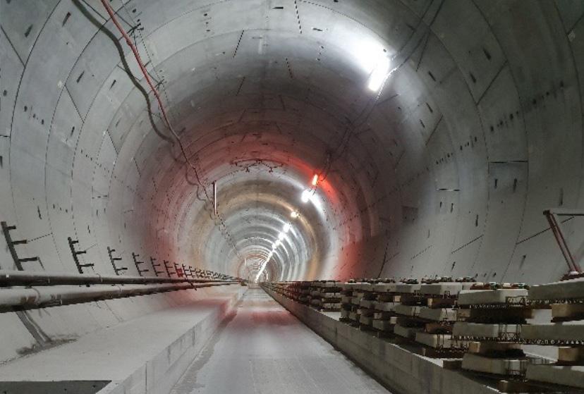
For areas where settlements could cause damage to buildings or other infrastructure, or where drainage into the tunnel was deemed likely to negatively affect the natural environment, a sensitivity classification was provided. This is shown in Table 15-1 below.
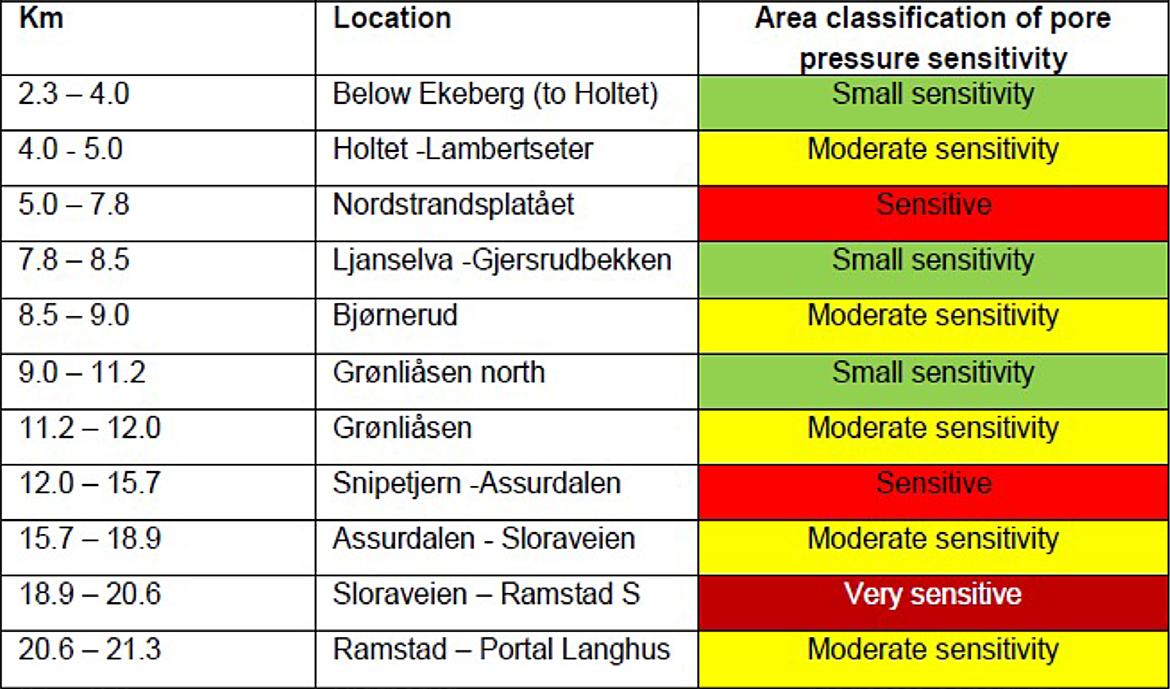
The classification depended on the risk related to pore pressure reduction of the area located above the tunnel and the occurrence of fractured zones. The risk was related to both settlement of buildings founded on soil deposits and sensitive natural environment.
In the TBM tunnels, a segmental lining with gaskets was chosen as waterproofing concept, and rock support. See figure 15-1 below. All D&B structures, like the rescue area tunnels, the escape tunnels and the cross passage are built as drained tunnels with rock support, water membrane and inner lining.
Contractor was required to ensure a dry tunnel and no dripping/visible flow of water was permitted whatsoever. In the event that such wet spots appear, whether through the joints between the segments or through the body of the segments, the contractor was required to propose and carry out remedial measures.
The gasket should be an EPDM (Ethlylene Propylene Diene Monomer) with high elasticity and low relaxation from the maximum water pressure over the design life.
Contractor should ensure water tightness of the connection between the segmental lining and the adjacent concrete structures, such as
• D&B (drill and blast) tunnel in the north
• Concrete tunnel in the south
• Cross passages
• Rescue area
Shortly before the tunnel excavation started the different neighbourhoods of the tunnel, all buildings located close to the tunnel-corridor were inspected internally in all rooms, including basements and attics. This also applied to any surrounding buildings like garages and parking basements.
All surfaces needed to be registered and the inspection should cover all existing damages like:
• Cracks in walls, floors, and ceilings
• Cracks in glasses and windows
• Cracks or chipping in ceramic tiles
• Moisture and traces of water leaks
• All doors and windows shall be checked for possible malfunction
• Potential settlements shall be registered
In addition to normal inspections, comprehensive inspections also included the following:
• Straightness of floors and possible building inclinations were documented by means of levelling. If inclinations were detected, they were illustrated with a sketch / drawing.
• Cracks were plugged to follow any further developments.
• Control inspection / registration just before the construction start and at the end of the construction period.
The inspections should be done with an HD camcorder. Lamps should be used where lack of light would otherwise impair the quality of the record-
ings. During recording, verbal comments for explanations were also performed. The recording of each unit should start with general information about the property and building, which should also include, among other things unambiguous identification of the property like address, date of inspection, who was present, etc. Provider should also state what type of equipment was used.
Exterior facades were inspected from street level unless special conditions indicated otherwise. If required, was the inspection done by boom lift. Exterior window posts and window frames etc. should be filmed as well to document any damage, usually done from inside with open windows. Exteriors should also be filmed with balconies or other structures providing access to exterior surfaces.
Exterior inspections should be avoided immediately after heavy snowfalls, when snow covered larger sections of exterior structures.
All exterior structures (bridges, walls, stairs, basins, monuments etc) should be inspected. The inspections should be so extensive that existing distortions and cracks could be documented.
In total, the Follo line project has carried out the following inspections:
• Detached dwelling units / townhouses etc. 2506 units
• Flats in apartment blocks 1520 units
• Commercial / industrial areas - furnished 294 230 sqm
• Commercial / industrial areas - unfurnished 32 311 sqm
An extensive monitoring program consisting of 170 pore pressure sensors in both soil and rock wells was established in due time before tunnel construction in order to register the natural seasonal variations in pore pressures. See figure 15-2 below.
The development of the monitoring program was a continuous and ongoing process throughout the project. After TBM excavation started, the number of sensors and the packer locations were updated based on experiences gained from the TBM excavation, in combination with geological mapping and the measurements from the pre-installed sensors. All sensors were logged automatically, and the readings were uploaded to a web-based GIS portal with a frequency of every 10th minute.
In addition to the pore pressure monitoring program, an extensive settlement program was carried out. Nails were installed on the foundation of more than 2,500 dwellings. The nails were manually surveyed in due time prior to passing with the TBMs
and after the TBMs had passed, and the readings were uploaded to a web portal. In addition to the pore pressure and settlement nails, a monitoring program utilizing satellite data (InSAR) from 2014 and up to date was established.
Figure 15-2: Pore pressure measured from 2014 and until both TBMs had passed and the pore pressure situation had stabilized.
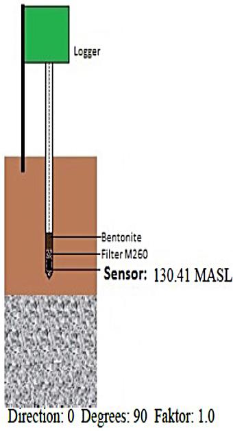
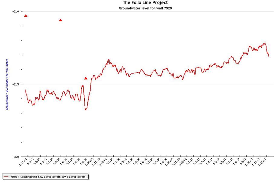
The contract required continuous and overlapping probe holes, at all times for each TBM tunnel. The number of probe holes were determined by the sensitivity classification. See table 15-1 above.
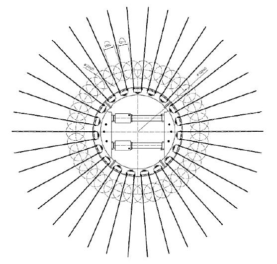
Considering the fact that the tunnels were excavated with double shield TBMs, the aim of the probe drill-
ing was to perform water ingress measurements from the holes in order to assess the further need for pre-grouting. Pre-grouting was performed to limit the leakages during excavation. There were 38 holes around the shield from where it was possible to perform probe drilling from the TBMs. This is illustrated in figure 15-3 below.
Figure 15-3: The cutterhead with the 38 inclined ports with 11o drill angle and DN80 pipes for probe-drilling. Illustration: Herrenknecht/ Acciona Ghella Joint Venture.
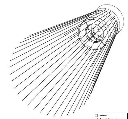
For the areas classified with “small sensitivity” contractor’s concept was to drill minimum two holes of 35 – 40 m from each machine during the daily maintenance shift.
The pre-grouting was performed either systematically in the mandatory areas, or when deemed necessary based on water ingress measurements from probe drillings. The trigger values from water ingress measurements were based on the sensitivity class of the areas above. During the excavation, the number of probe holes and the trigger values were optimized in order to maintain the groundwater balance.
A total of 28 temporary infiltration wells were installed at 13 different locations. The wells were operated from surface and acted as additional mitigation measure for groundwater control whilst the TBMs passed. The wells were successfully operated. The infiltration wells were drilled 20-50 m in rock, preferably inclined under soil deposits, se figure 15-4. Water with some overpressure was infiltrated through the rock well and into fractures in the rock. Both pressure and flow were controlled to avoid piping effects in the overlying soil.
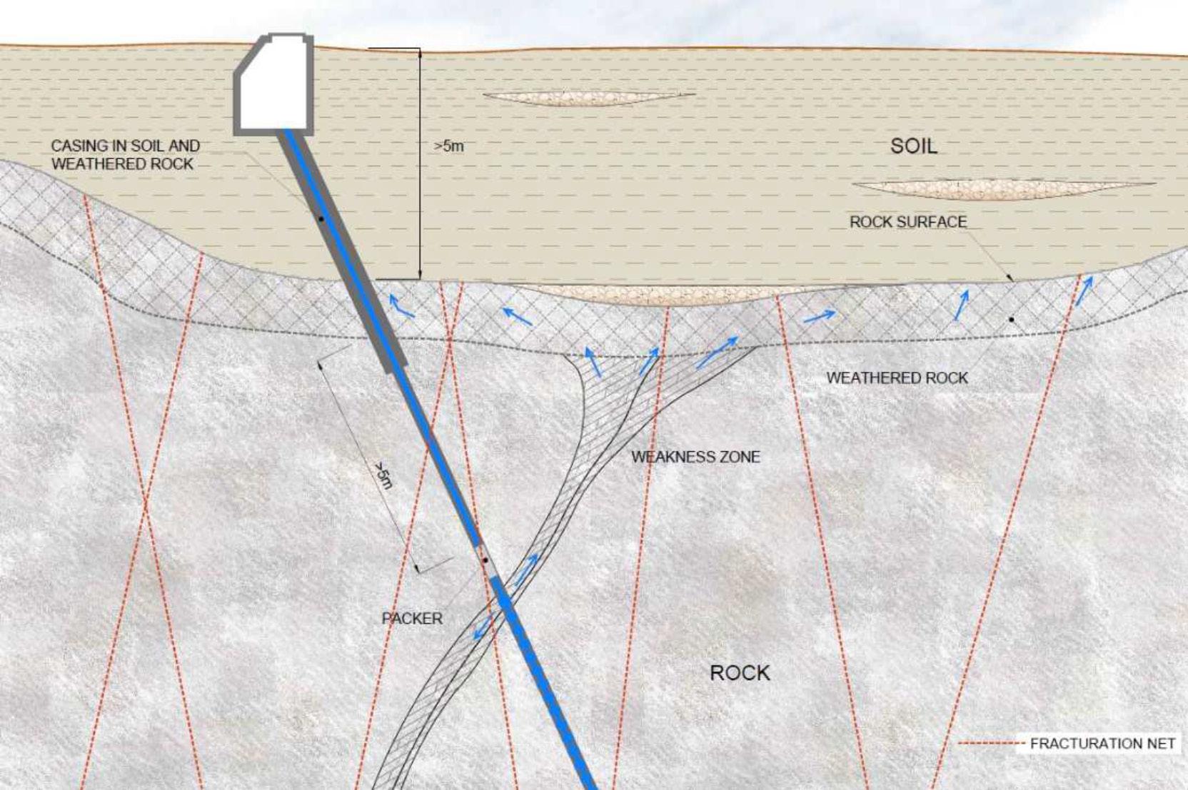
The first construction method statement for preexcavation grouting submitted by contractor was basically a copy of the client’s original proposal without considering the specific boundary conditions of the bi-component backfill material for the ring gap. contractor decided to fill the ring gap from 2 o’clock position to 10 o’clock position through the grout ports in the tail shield and then fill the crown area from the back-up, without having any possibility for re-injection along the back-up. This meant that no water barriers were installed on the back-up to avoid water running behind the lining along the TBM tunnel and entering in front of the installed segments. Without having this possibility, the construction concept was fully dependent on the success of pre-excavation grouting. The limits established by the client for pre-excavation grouting were assuming a watertight tunnel behind the TBM, and water barriers to avoid water running along the TBM tunnel. As a consequence of this, the trigger values for pre-excavation grouting had to be reduced several times.
Table 15-2: Trigger values for pre-excavation grouting in Bane NORs original concept.
This learning curve resulted, especially at the beginning of the TBM excavation, in water ingress into the tunnels, which caused a lowering of the pore pressure in the sediments above the tunnel. The water entering had high content of bi-component backfill material, which required an exhaustive water treatment.
On the 7th of December 2016, TBM 4 boring in the southward direction, crossed a semi-horizontal fracture zone, which resulted in water leakage into the tunnel. In this area, only one probe hole, located in the upper part of the profile had been performed, and this was not sufficient to detect the water-bearing cracks. Therefore, no pre-excavation grouting had been carried out in advance to stop the water ingress when the TBM hit the fracture zone. It took several weeks until the situation was brought under control. TBM 3 also entered the same zone and suffered water ingress as well since no pre-excavation grouting having been done in this case either. The immediate amount of leakage in TBM 4 was somewhat uncertain. On the 8th of December 37 l/s was measured and from the 23rd of December to 3rd of January the average was 14 l/s.
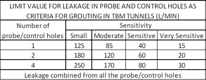
Table 15-3: Adjusted trigger values for pre-excavation grouting during the excavation period.
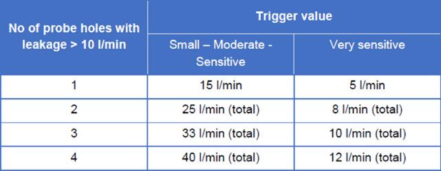
These leaks did probably cause settlements on buildings in a residential area located at a direct distance of 700 m in a horizontal line from the tunnel alignment. On the 7th of December 2016, the tunnel face was approximately 1300 m in a horizontal line from this area, and on the 17th of March the distance was approx. 900 m. This was outside the area that originally was expected to be affected by the pore pressure reduction due to the tunnel operation. As shown in figure 15-5, the tunnels crossed a network of fracture zones with N-S and NE-SW directions. Each of this fracture zones illustrated in the map have a thickness of more than one meter. In between there may be fracture zones with less thickness as well. The network of fractured zones acted as drainage channels, which contributed to reduce the pore pressure in sediments located quite far from the tunnel-corridor. This is also described in Chapter 14, “Geological mapping and follow-up during the TBM excavation”.
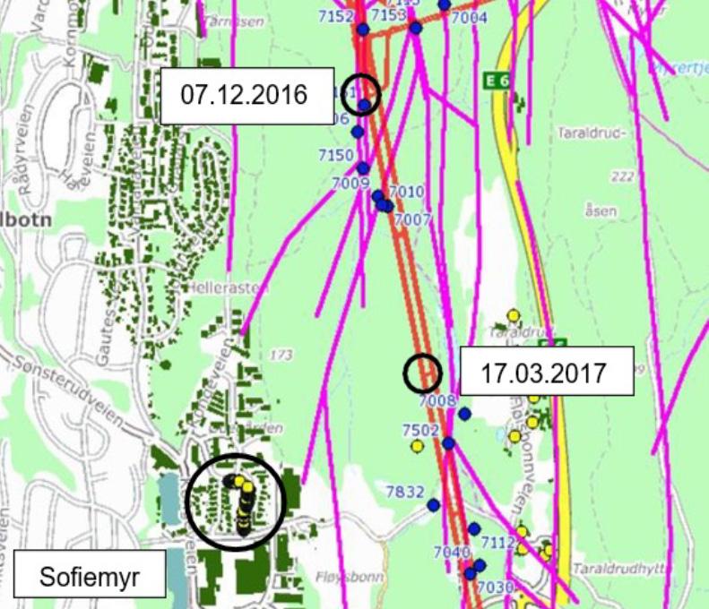
In summer 2017, the project organization became aware of development of possible settlements in the residential area located 700 meters from the tunnel corridor. Two pore pressure sensors had been installed there, 7060-1 and 7060-2, at 5.4 and 8.4 m depth, respectively. Figure 15-6 shows relevant pore pressure fall and water level measurements in the rock close to the tunnel alignment. The pore pressure in the deepest meter was then about -4 m compared to the stabilised value at the end of 2017. This, together with several other pore pressure sensors, located closer to the tunnel alignment, which had shown declines, had all stabilised. A well at a nearby farm, also at this area, went dry while the pore pressure was reduced on the affected residential area, but recovered later.
Figure 15-5: A network of fracture zones (purple color) and black rings marking the position of the TBMs at specific dates and the location of the affected residential area.
Some of the houses in this area are founded on rock, whilst in some specific cases the basement floors are founded on soft ground (marine clay and some peat). An analysis of InSAR settlement data showed ongoing settlements for the buildings over several years, however it appeared that the water ingress into the tunnel, with corresponding temporary pore pressure reduction in this area, accelerated these
settlements for a short period. Since this area was outside the initial detailed monitoring zone of the project (350 m on each side of the corridor), a limited number of data were available for these specific cases. When the TBMs had passed this area, and the water leakages into the tunnel had been stopped, the pore pressures were re-established. The project took responsibility for the temporary drop of the pore pressure and for the development of settle-
ments in the affected areas and repaired identified damages of buildings.
Experience have shown that areas far away from the tunnels (in this case > 1300 m) can be affected by pore pressure and water reductions due to tunnel excavation, if large leaks are not sealed quickly. In soft soil areas, this can lead to drainage and settlements of buildings.
Figure 15-6: Measured porepressure levels in the area close to the affected residential area.
Another example is taken from the TBM drive towards Oslo, in the northward direction.
As TBM 1 and 2 approached a specific residential area in the autumn of Oct / Nov 2017, pore pressures reacted almost instantaneously in both south and north areas of the positions of the TBMs. The farmland here was particularly exposed. Settlements were previously shown here while the work on a new construction area was completed in 2015/16. This had resulted in occasional settlements in this area of up to 10-15 mm.
During the fall of 2017, a new pore pressure reduction of approximately 8 m was detected at sensor 4857 and reactions in several other sensors were also registered. This is shown in figure 15-7 below. Pre-excavation grouting from the TBMs was performed before passing under the area, but only when the segmental lining was in place did the pore pressures rise again to normal levels. The pore pressure reductions resulted in settlements of up to 25 mm, which is shown in figure 15-8. The settlements started as soon as the pore pressures dropped, and they stopped as suddenly as they started when
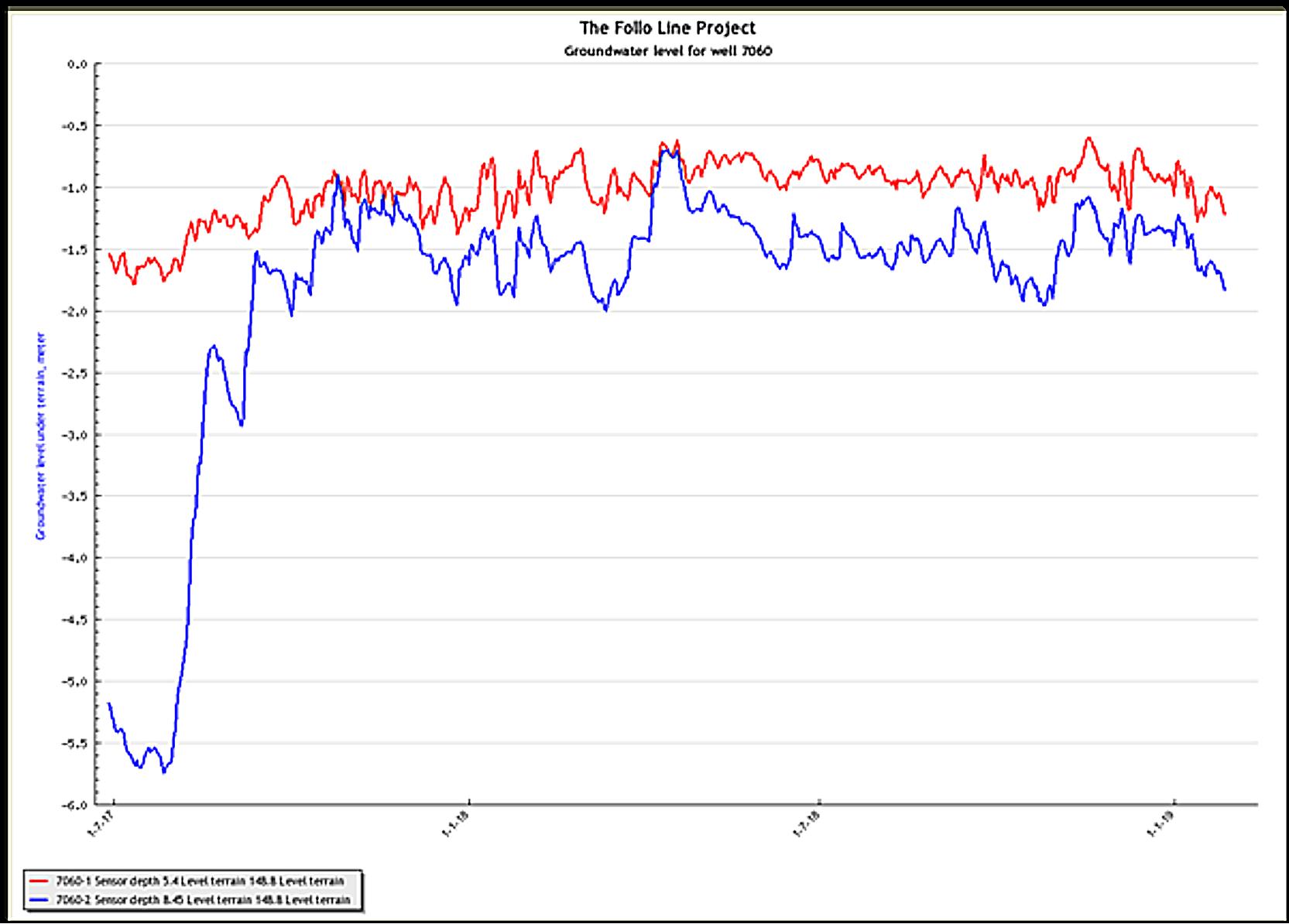
the pore pressures were up again. The settlements appeared to be of a relatively harmless type. No significant damages were reported. That was probably because the differential settlements seemed to be small.
Water infiltration from three different rock wells in the area may have had some significance effect to bring the pore pressure up again. The water infiltration wells were temporary until leakages into the tunnel had been stopped. When a pore pressure balance was achieved, the infiltration wells were demobilised.
Figure 15-7: Pore pressure levels in one of the affected areas in the northern part of the tunnel. It showed a significant drop while the TBMs passed and were not re-established before the leakages into the tunnel and the cross passages had been stopped.
Figure 15-8: Development of settlements in the affected area corresponding to the pore pressure situation shown in figure 15-7 above.
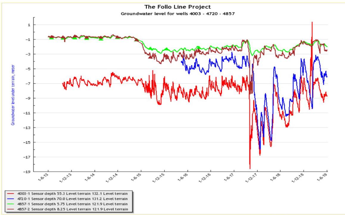
As a result of the water ingress through the TBM shield, a reaction was registered in observation wells in rock almost one kilometre from the tunnel alignment. This shows that probe drilling in front of the TBM with a sufficient number of probe holes, customised for the geological conditions and the sensitivity zone classification, are essential to detect fractures with high permeability and to avoid situations like this.
In the beginning of the excavation period, the contractor decided to start with performing only one probe hole located at top centre position and drilled approximately 30 m in front of the TBM cutter head. Later experience showed that this strategy was not sufficient to detect all fractures with high permeability. A revised strategy for the probe holes was implemented to adapt to the encountered geology. The new concept involved minimum two holes, located at top and invert of the tunnel, which was also more in line with the client’s advice in the tender documents. The leakage criteria for when to start pre-grouting from the TBMs were also revised. Trigger values at the Follo Line project were, after some experience, set to 40 l/min total from mini-
mum two probe holes in moderate to sensitive areas. Experience showed that increasing the number of probe holes to four provided more reliable information of the conditions ahead of the TBMs. It was then also possible to detect fracture zones which crossed the tunnel with a small angle before they were hit by the TBMs. In areas with small sensitivity, around 80 l/min was experienced as a maximum value for water ingress to avoid problems with the backfill grout. In some of the sensitive areas, the number of probe holes were increased to six and the trigger level reduced to 25 l/min in total from all the probe holes, whilst mandatory pre-grouting was required for some of the areas classified as very highly sensitive. In other areas, defined as very highly sensitive, the trigger value for starting pre-grouting was set to 8 l/min in total from all the six probe holes.
Based on experience during the excavation, the number of systematic probe holes were increased for all the sensitivity classes, and the trigger values for starting pre-grouting were reduced. The development of trigger values is illustrated in figure 15-9 below.
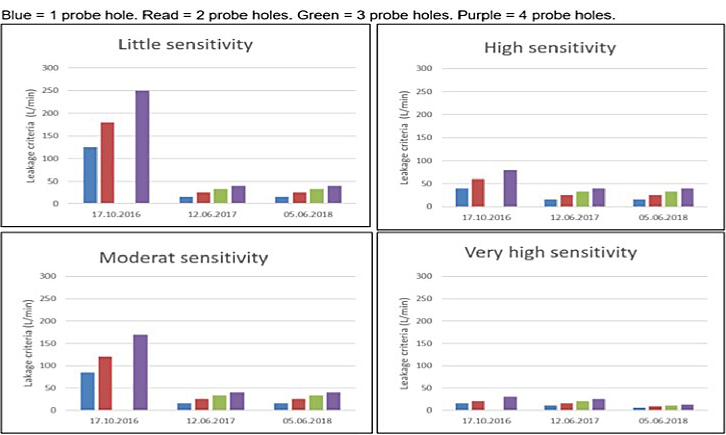
Another observation in areas with leakages through fracture zones, was that the water ingress also resulted in outwash of the cement based backfill which was injected behind the lining. This outwash increased the water flow behind the lining, which resulted in even more outwash of material, and in some cases a destabilizing of the lining as well. From an early stage of the excavation period, it was obvious that the contractor needed to improve their strategy and methods for handling the water as an integrated part of their construction.
As a consequence, many pre-excavation grouting rounds were performed, and in total 7.637 meters of the tunnels were pre-grouted. In the beginning, contractor used approximately 30 hours at the entire process, from probe drilling until finalizing one pre-grouting umbrella. In the end of the excavation phase, the time needed to perform the entire sequence was reduced to approximately 15 hours.
Contractor did never inject more than 20 holes in one umbrella, even though it was possible to inject from 38 exits. By utilizing all the exits when drilling for the umbrella, the quality of the injections would have been improved, and in some areas the water behind the lining, including the outwash of backfill material, would probably have been reduced.
The two TBMs which excavated in the southward direction crossed more fracture zones than the TBMs heading northwards. As a consequence of that, a higher number of pre-grouting rounds were performed in the south than in the north, 40 – 65% more. TBM 4 was ahead of TBM 3 most of the time, and TBM 3 may have had some benefit of the pregrouting performed from TBM 4. This is shown in Table 15-4 below.
The amount of cement used in the different pregrouting rounds varied, but for the two machines heading south, the average volumes seem to be more or less the same. These volumes are comparable to the volumes per round and also per hole
Table 15-4: Number of pre-grouting rounds for each of the TBMs.
measured for TBM 1. The volumes for TBM 2 are lower. One of the reasons for this may be that TBM 2 were behind TBM 1, and may have had benefits of that, even though the number of pre-grouting rounds were approximately the same. The volumes are shown in table 15-5 below.
The cross-passage excavation is always a critical operation in a twin tunnel concept. Loads from the segmental lining need to be transferred to adjacent rings and water ingress shall be avoided. Since the TBM tunnels were excavated in stable rock mass, the ground loads were relatively small, and the main loads were water loads. The design was optimised in a way that only three special segmental lining rings for the opening area were required.
The procedure for excavation of cross passages, similar to the TBM excavation, had focus on reduction of water ingress and during a learning process, the construction method statement experienced several revisions. At the beginning basically no contact grouting was performed in the TBM tunnels in order to reduce water ingress from the main tunnels, only rock mass grouting from the main tunnels into the cross-passage areas were performed. This concept resulted in uncontrolled water ingress at the cross-passage openings, which resulted in a lower-
Table 15-5: Cement volumes used for pre-grouting for each of the TBMs.
ing of the pore pressure and the groundwater levels. A typical behaviour is illustrated in figure 15-7 above. The drops after the TBMs passed can be related to cross passage openings in the area.
A combination of cementitious grout performed as contact grouting and injection of polyurethane rings around the cross passage opening provided sufficient reduction in the water ingress from the main tunnels during opening. In fractured zones, rock mass grouting was required as well.
The most effective method in terms of water ingress reduction was pre-excavation grouting from the TBM as a preparation for the later opening of the crosspassage. At a certain point, this decision was taken to perform pre-excavation grouting from the TBM at cross passage openings, usually with two umbrellas. This is described in more details in Chapter 13, “Opening and excavation of the cross-passages”.
In total, the handling of water improved during the excavation phase, and in the end the detection of water and the performance of pre-grouting were executed in an efficient way. The result was limited periods with reduced pore pressure and limited settlements on affected buildings.
A lesson learned is the importance of paying attention to areas where leakages may occur, and of being well prepared to handle the leakages in advance by pre-grouting. Good knowledge and understanding of the geological conditions are always one of the key factors to success. Another crucial factor for the project was to prepare the TBMs for pre-grouting. During the excavation, a utilization of the opportunities to improve the quality of the pre-grouting umbrellas by injecting more holes, could have been done. This could have reduced some of the leakages that occurred through the lining, and then the need for performing post-grouting.
One of the main success factors regarding water tightness is a 100% filled ring gap to limit the amount of water just behind the lining. This can usually only be achieved, if additional round of injections are performed after the first ring gap filling, especially when washouts may have occurred.
On the other side, the machines excavated 9 km of tunnels each within a period of approximately two years, even though they performed pre-grouting over a total length of 7.637 meters. This execution has demonstrated that neither the hard Norwegian rock, nor the need for doing pre-grouting in order
to stop or reduce water-leakages are show-stoppers for TBM-tunnelling.
Acciona Ghella Joint Venture (AGJV) assembled three precast factories to produce the precast rings, to feed the 4 hard rock TBMs; the first factory had its start-up in May 2016 and the third in September the same year. The precast rings were made of 7 pieces (6 segments + 1 key segment) and one invert segment. The concrete strength of the segments is 55 MPa.
The factories were placed in the upper area, close to the spoil shed, as the first intention was to reuse the material coming from the excavation of the TBMs to produce the aggregates for the concrete production. In this way, both the spoil shed, crushing plant, aggregate shed and precast factories were located in the same area. Layout was focused on re-use of
the spoil from the excavation, area constrains and optimization. The area available for all the activities related to the tunnel excavation, including deposit of 9 million tons of spoil and production of the lining for the 20 km long twin-tube, constrained challenged not only for the layout design, but also for the running day by day activity.
Around 20.000 precast rings were produced in the project; this required more than 460.000m3 of concrete and 18.000 tons of structural steel. This led to the biggest cement contract ever awarded in Norway.
In regular conditions, one precast segment was produced in Follo Line every 5,6 min.
The material from the TBM´s was planned to be used for the production of the segments, and the entire production was organized in order to fulfil this intention. The excavated material was transported by a conveyor belt system from each of the TBMs.
These tunnel conveyors, C1, C2, C3 and C4, unloaded the spoil on two cross conveyors (named CT-N and CT-S) placed in the central cross passage of the rescue area tunnels.
Tunnel conveyors C1, C2, C3 and C4 had a capacity of 1000t/h (belt width: 1000mm), designed for a TBM advance speed of 80mm/min. The rest of the conveyors (inside the rescue tunnels, adit tunnels, and overland conveyors had a capacity of 2400t/h each (belt width: 2400mm).
The excavated material was transported by conveyor belts to the spoil shed, which was located approximately 500 meters from the tunnel portals. From
the conveyor belt, the material was dropped into the spoil shed and from there delivered to the crushing plant, where the aggregates were produced and stored in the aggregates store. From this place, the aggregates were transported to the batching plants by a conveyor system.
Shortly after the start-up of the aggregate production, presence of pyrrhotite in the material was discovered. In some of the samples, the content of pyrrhotite was too high to be used for concrete pro-
duction. It was not a clear picture of where pyrrhotite was present or not, so massive and continuous testing was needed to sort out the material which was pyrrhotite-free. The production line was not prepared for such massive testing, so it was decided to stop the crushing of the excavated material for aggregate production. Instead, commercial pyrrhotite-free aggregates were used for the concrete production. This is described in more detail in chapter 9 “Use of the tunnel spoil”.
The detail geometry of the rings is shown in table 16-1 below:
Internal ring diameter 8750 mm
Segment geometry Universal ring with parallelogram segments and trapezoidal key
Segment length 1800 mm (nominal)
Segment thickness 400 mm
Segment taper 40 mm at trailing edge
Table 16-1: Geometry of the segmental rings.
Each ring consists of the following segment accessories:
• Dowels – 19 per ring in normal rings
• Fama dowels – 38 per ring in X rings
• Spear bolts – 14 per ring
• Guide rods – 7 per ring
• Packers – 38 per ring
• Gasket – 1 anchor gasket per segment; The water tightness of the gasket was tested and verified for the design pressure of 33 bar at the theoretical gap, with an additional 5 mm tolerance to account for evenness imperfections and installation tolerances. It´s relevant to mention that the segments were designed without bolts between adjacent rings.
Each ring consists of the following quantity of segment recesses:
• Grout sockets – 7 per ring
• T20 sockets – 19 per ring
• Vacuum lift sockets – 14 per ring.
There were three independent factories, each one with its own carousel system and a batching plant.
As described in Chapter 12, “Infrastructure, logistic and the TBM boring process”, AGJV reduced after contract award the number of factories from 4 to 3.
Due to the special weather conditions, the batching plants, aggregate shed, and factories were covered.
Inside the factories, each one had 2 gantry cranes, the first one to demold the segments, the second one to move the segments in to the pre-storage area.
Space constrains also stressed the need of good lay out when it came to rebar preparation.
There were also two factories where the reinforcement cages were assembled. They arrived preassembled from Germany, and on site they were welded in a template until the final form. There were different types of reinforcement cages in correspondence of the position of the ring in the tunnel (overburden and distance from the portal)
Two extra gantry cranes were installed in the reinforcement factories to handle the steel cages.
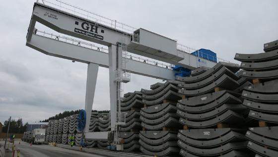
The storage area for the segments were split in three different areas around the factories. Each area had their own gantry crane. With this crane, the segments were moved from the pre-storage area, inside the factory, to the storage area, and from the storage area to the Multi service vehicle (MSV) to be transported into the tunnel. The crane was equipped with a clamp, able to lift 4 segments at the same time. In this way, one complete ring could be moved in two movements.
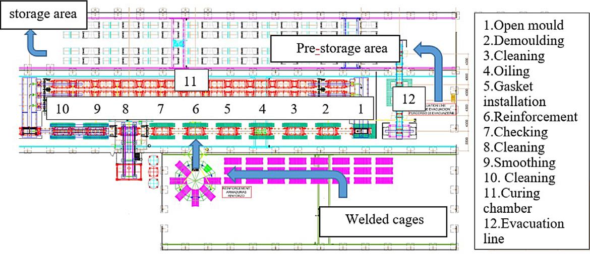
The mixers of the batching plant had a capacity of 2m3 per batch.
More than 200 workers were involved in the precast production during the period when all the three factories were in operation. The activities related to production and loading of segments for supporting the four TBMs took place around the clock. In total, more than 1 million working hours were performed during approximately 2 ½ years of production. During this period, there were no serious accidents, although the high number of hours worked, and the risk activities like the lifting of each of the 161.000 segments, which happened minimum four times per piece (de-molding, pre-storage, storage, and loading).
Each factory had a total of 48 molds to complete 6 precast rings. The distribution of the molds could be split in two areas, the working line, and the curing chamber. The pieces were produced with high precision and the tolerance of the molds was checked regularly. The tolerance was ±1mm in the diagonal measurements and less than 0,5mm in the other dimensions.
The working line had 10 positions in total, in the first one, the mold with the segment had just come out from the curing chamber and the mold was opened. The segments were de-molded/ lifted up from the mold with a vacuum clamp.
Then the mold was cleaned, oiled and gaskets installed. In the reinforcement station, the steel cage
was installed inside the mold and the mold was closed. In this point, everything was ready to start the casting. This pouring was done in the concrete station. There the batching plant operator produced the concrete and coordinated the activity with the carousel operator. From this position, all the workflows were coordinated, and it was only the carousel operator who could move the carousel. To do that,
the different positions in the working line had to approve the movement by pressing a button when they have finished their activity.
The concrete to produce the segments, had a slump requirement between 10 and 40 mm to be able to reach the strength in a short time. In order to fill the mold completely, surface vibrators were needed in the mold in addition to a high pressure of around 8 bar.
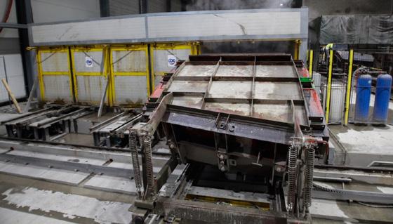
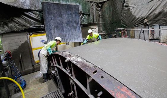
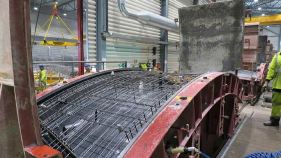
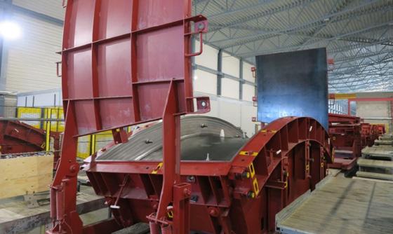
Each ring was produced in around 50 min, this performance was possible due to the curing chamber. Here, the concrete was cured with the proper temperature and humidity conditions to be hard enough for de-molding around 5 hours after the casting.
The concrete temperature was also important to get this early strength. This temperature should be around 20ºC. To reach it, in wintertime, the concrete was produced with hot water and warm aggregates. To achieve this, a boiler system was implanted in the batching plants.
When the segment left the curing chamber, the mold was opened, and the segment was de-molded with a vacuum clamp. This vacuum clamp transported the segment to a turning device, where the
segment turned to its final position. In this position the segment was transported into the pre-storage area though the evacuation line. Here the operators evaluated the segments and performed repair in case that was needed.
Once the segment was casted, the mold was opened again in order to properly finish the upper surface in the mold. After that, the mold was closed again and was sent into the curing chamber.
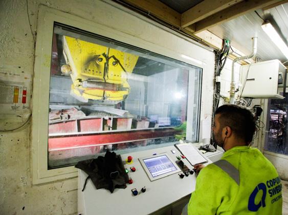
Due to the special conditions during the wintertime, with temperatures below -10ºC, in combination with the temperatures of around 45ºC in the segments when they left the curing chamber, special mitigations were implemented to avoid thermal shocks in the concrete. This could affect the strength development and thermal stress cracks could occur. An indoor pre-storage area was designed in each
factory. This area had capacity enough to keep the segments around 2 days before they left the factory building.
In this point, the segments were already stored in packages of 4 segments, so the external storage crane could handle them in packages of half rings.
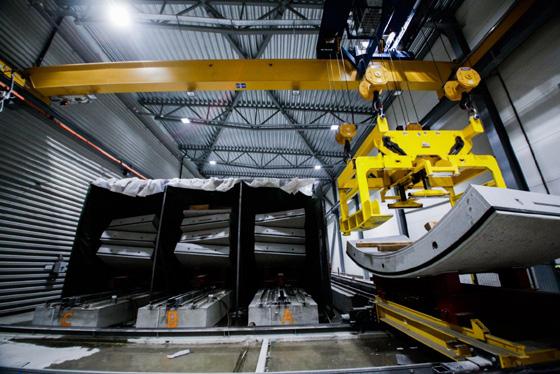
The segments were transported to the tunnel and further down to the TBMs in a multi service vehicle (MSV), which was able to transport two complete rings at the same time, dealing as well with thigh curves and significant slopes.
The segments were sequenced from segment A to segment B1, B2, B3, B4, B5 and the key (K), which was also the construction sequence for the complete ring. Before the segment installation of the ring, the excavation and the re-gripping were be done.
The complete procedure of ring build included the following steps:
• Unloading of the MSV in the TBM backup
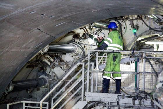
• Segments were transferred to ring building area by the segment crane and feeder
• Ring position selection
• Ring erection
The segment crane operator operated the crane and placed the segments on the feeder in a direction so that the front edges of the segments were facing the TBM, and the trailing edge of the segments were facing the portal.
The ring selection process took place after re-gripping was completed and before the next ring should be built. The precast segmental lining was designed in such way to allow 19 different positions to be built. The rings were “universal rings” which meant that the tendency of the ring alignment was solely based on the ring position, and there was not a left- or righthand ring option.
Each segment was erected in the sequence A, B1, B2, B3, B4, B5 and K (key segment).
The erector operator picked up the A segment with the vacuum plate and controlled the segment into the desired location according to the confirmed ring selection. The installed dowel on the segment should be precisely aligned with the dowel socket on the front edge, and the steps at the circumferential joint should be flushed with the previously built ring.
After the segment position was confirmed, the erector operator controlled the ram to extend and push the A segment into the final position. A similar method applied to installation of the B1 segment; the erector operator controlled the B1 segment to ensure that the guide rod groove on B1 segment fitted on the guide rod installed on A and pushed the B1 segment into the final position.
The same methodology applied from B2 to B5 and K.
Spear bolts were inserted at the radial joints by the segment installers after the final installation of the ring.
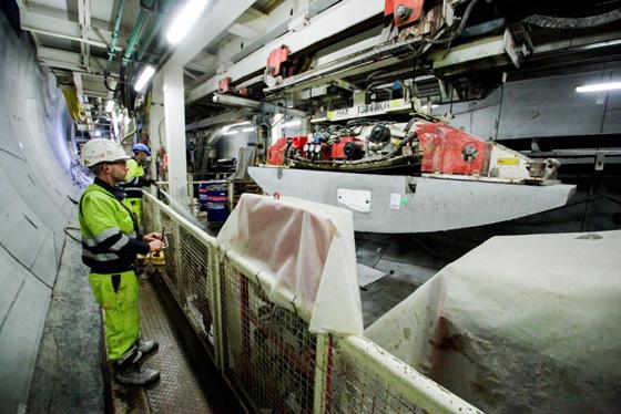
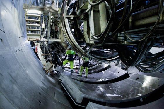
In order to provide stability of the precast ring, the space between excavated rock surface and the outer part of the ring (annulus) had to be filled. This was carried out as described below.
The primary annular filling injection was performed from eight double lines through the tail shield. This operation allowed filling of the lower part of the annulus.
The mix design per batch of component A was a mix between cement, bentonite, retarder, and water.
The upper part was filled in secondary filling stage.
One grout socket was embedded in each segment. The grout sockets were caped before the extrados of the segment. Before injection through the segment the cap of the grout sockets had to be drilled through with an approximate 25 mm drill bits. The
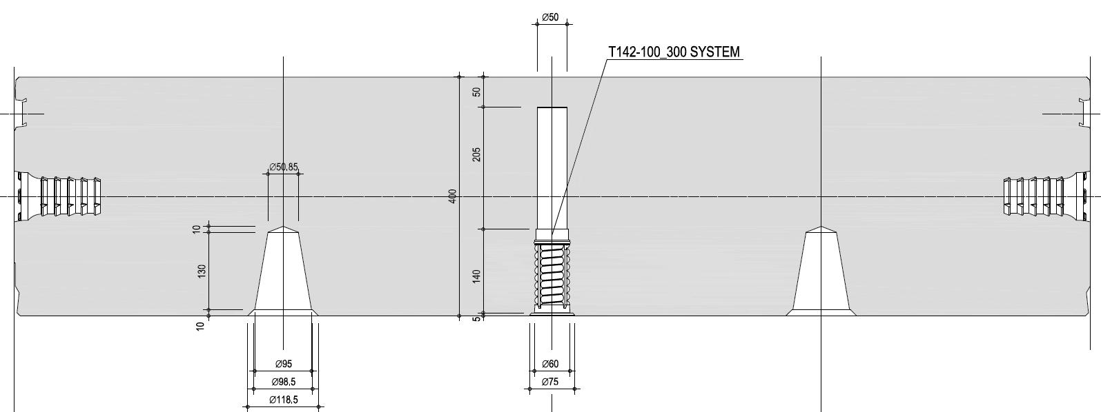
non-return valve was installed to prevent grout back flow after injection, and it was fitted in the grout socket after penetrated the segment and before starting of grout injection.
Bi-component grout should completely seal the grout socket at the completion of each segment injection. This was achieved by avoiding flushing of the lines with component A through the grout socket before removing the injection packer. A three-way valve was introduced just before the segment injection packer, so when the injection was finished and the pressure had been reached, the three-way valve was switched so that the bi-component flow was re-directed towards the flushing line. By this procedure, the grout socket was filled with compacted bi-component grout and ensured a complete seal of the grout socket. The grout operator then switched off the component B pump so that component A ran through the mixing nozzle and flushing lines for around 5 L. Refer to illustration below.
The key of batching the grout at the mixer on surface was to ensure that the material mixed in the mixer was following the mix design.
To achieve the right mix design, the weight of the raw material such as cement, bentonite, water, and retarder to be discharged to mixer was adjusted at the grout plant control panel.
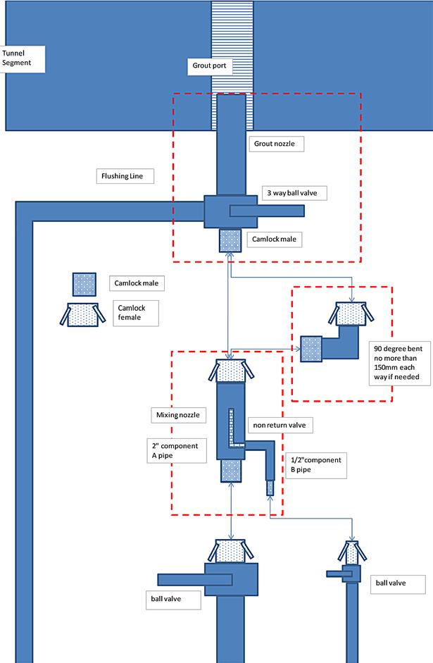
The backfill grouting system was auto mode, which meant that the grout plant on the surface was synchronized with the grout injection system on the four TBMs. The component A and B pump on the surface was automatically activated and transferring the components from the bi-component plant on the surface to their staging tanks on TBMs gantries until the upper threshold of the staging tank was reached. The surface pumps could also be operating manually from the surface control panel. But this was limited for exceptional cases.
The backfill grouting concept was to complete primary grouting cycles with injection through the shield for the lower 265 degree of the tunnel annulus. Followed by completing the secondary backfilling of remaining top 95 degree of tunnel annulus through the grout ports of the segments. This concept had the following benefits:
• Injection through the shield minimized the possibility of breaking the segment behind the grout ports
• Reduced amount of pressurized backfill material in the tunnel crown to lower leaking of bicomponent grout into the TBM system
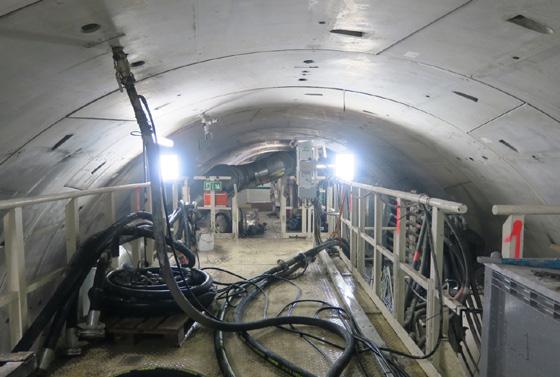
• Minimize pressure on spring plate reduced the delay related grouting contaminating the grippers.
It was crucial to provide immediate support at the invert of the ring whenever the built ring became suspended from the tailskin. The primary grouting should start when the tailskin moved forward and forming a 300mm clearance between the spring plate and previous grout. The grout flew from all
injection ports except the two lines at the top of the tail skin forming a support to the ring of 265 degrees. In double shield mode, the tailskin moved forward by retracting the main thrust cylinder and extension of auxiliary thrust cylinders during “regripping” process. In single shield mode, the tailskin moved forward extending only the auxiliary cylinders as the machine advances.
The injection of the remaining 95 degrees was executed with the secondary grouting through the segments at specific grout socket injection locations. The injection took place from the mobile platform at the top deck of the bridge or from the stairs that connected the top deck to the middle deck.
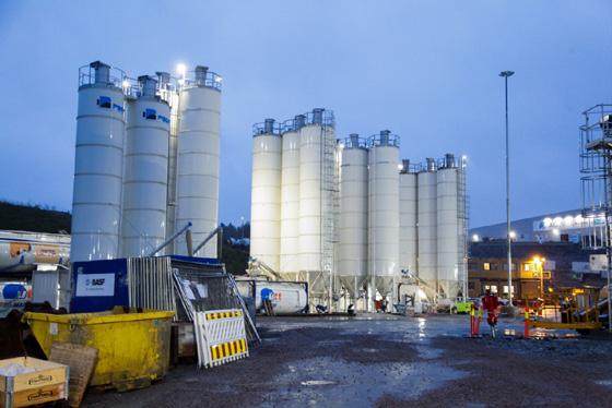
The injections were performed approximate 6 rings behind the last installed ring using special injection nozzles, as illustrated in figure 16-20 and 16-21 above and in figure 16-23 below.
For the secondary grouting, the component A mix was the same as used for the primary grouting by the tailskin injection. The dosage of Sodium silicate for the B-component was different. The final mix had a higher gel time, in order to be able to inject two or more rings in one time. This dosage difference had an impact on the short-term strength, but as this was an injection for the top part only, it did not need this early strength to sustain the ring. The mix had a dosage of component B at approximate 6%. Gel time was assessed during grout trials and dosage could be changed accordingly.
The TBM sections of the Follo Line tunnels have a single water barrier consisting of segmental lining with gaskets. For the ring gap filling has the contract defined the following principle requirements:
Contractor shall develop a grout mix for backfilling the ring annulus. The mix characteristics shall be suited to the selected construction method, proposed plant, and advance rates. Consideration shall also be given to geological conditions and in particular ground water ingress. Pea gravel is not acceptable. The grout shall remain effective for the design life of the tunnel and shall not degrade, shrink, or lose strength to an extent that the tunnel structure and performance would be compromised. The grout shall be sufficiently fluid to ensure that it flows into all parts of the void.
Acciona Ghella Joint Venture (AGJV) choose to use a bi-component grout pumped from the surface. The injection process is described in detail in section 11a, while in this section the focus is on the technical specifications and the specific behaviour.
The bi-component grout is characterized by being composed of a stabilised pumped cement-based grout A-component and by a B-component which acts as an accelerator. Separated one from each another, the two components are practically inert, and the hardening only starts when the two components are mixed. During the injection process the two components do not mix until they reach the end of the injection line (injection nozzle), hence right before reaching the annular gap. Additionally, opposite to the traditional grout which needs 4 to 8 hours for hardening and obtaining a certain degree of strength, the bi-component grout develops a typ-
ical gel structure in a few seconds which guarantee a degree of bearing capacity at an early age which allows the quality ring behaviour and filling between the segments and the rock mass.
The A-component is a grout suspension composed of water, bentonite, cement, and a stabilizer. The purposes of each element are:
• Bentonite: Increases the shear strength and the ability to absorb water from the suspension which grants a thixotropic behaviour. In this way the suspension is less viscous and flows better.
• Cement: Acts as the binding agent and controls the hardening time. The water/cement ratio is decisive for the final properties of the grout regarding the strength.
• Water: Allows the hydration of the cement. Its amount controls also the fluidity of the mix.
• Stabilizer/retarder: Decelerates the hydration of the cement and avoids the A-component reacting during the injection process. Its function gets disrupted when mixed with the B-component (accelerator).
These components are natural and due to the variability of their nature, the characteristics of the suspension can vary too. Consequently, the dosages should be dimensioned and tested for the different products in the particular conditions of each project.
The B-component is a sodium silicate. The percentage of the component B determines the gelling time and the early strength of the gel. The component B is an accelerator which counteracts the effect of the stabilizer in the A-component and allows the hydration of the cement.
The material parameters were defined as:
After an intense testing with the specific product used for the Follo Line, including injection trails, the
following mixes were proposed:
Table 17-2: Proposed backfill grout mixes.
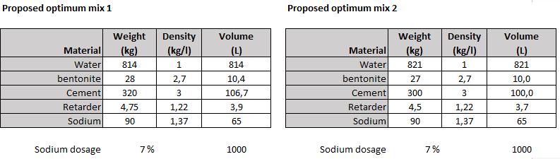
The advantages of bi-component grout over conventional grout mixes are summarised next:
• Bicomponent grout provides fast bedding to the ring which is coming out of the tailskin shield. In this way the risk of deformation and undesired steps in the segmental lining is reduced.
• The appropriate adjustment of the grout mix components allows a good control of the gel time and strength development in early and later stages.
• The previous point is especially relevant when working in unpressurized shield drives such as with double shield technology. When no front counter pressure is available, there is a high risk of the backfilling grout to flow forward towards the shield, increasing the risk of the shield to get trapped in the ground.
• Due to the fast hardening of the grout around the latest installed rings, the deformations and rotations of the ring, caused by the thrust jacks and the rotation of the cutting wheel, are reduced.
• The two components are inert when separated from one another, the risk of clogging in the lines is drastically reduced. The breakdown times for cleaning the grout lines are minimised which improves the overall TBM performance.
• The fast strength development of the bicomponent grout reduces the risk of the grout being washed out because of groundwater flows which can occur in the annular gap.
• The low viscosity of the two components allows to pump them from the tunnel portal to the TBM without the need for grout transportation by vehicles, which results in reduced logistics requirements in the tunnel.
• The equipment on-site is considerably smaller than with conventional grout where a mixing plant is required.
The disadvantages of the bi-component grout are:
• Compared to pea gravel higher risk for wash out.
• Cumbersome cleaning process of the water contaminated with bi-component grout.
• The specific materials used for the Follo Line resulted in a relatively high pH-value of the contaminated water, causing risk for health of humans and material durability.
• Build-up of calcite formations of water entering the tunnel system.
Over various years, client and contractor discussed potential consequences of frost in combination with water leakages in the tunnel.
Since the backfill grout consists during installation of approx. 80% water, the risk of potential expansion during freezing, and as such build-up of intolerable pressure to the segmental lining was identified. The second concern was related to the structural integrity of the backfill grout. Therefore, extensive testing in small scale, but also in bigger scale were performed.
Small scale freezing test
Mapei, the supplier of the backfill grout, did small scale testing, which were verified with the exact same products and mix design at SINTEF in Norway.
Five steel molds with backfill grout samples were received 2019-09-19. One mold was equipped with cast-in thermocouple. The molds were filled with grout and sealed by Mapei at their abortorium at Sagstua (Norway) 2019- 07-30. The cylindric grout sample was 40 mm in diameter with height 40 mm. A photo of a sealed mold is shown in Figure 17-1.
The original Ø15 mm steel bolts were replaced by Ø8 mm (quality 8.8) steel bolts. Two bolts were equipped with surface strain gauges. One of the molds had cast-in thermocouple for monitoring
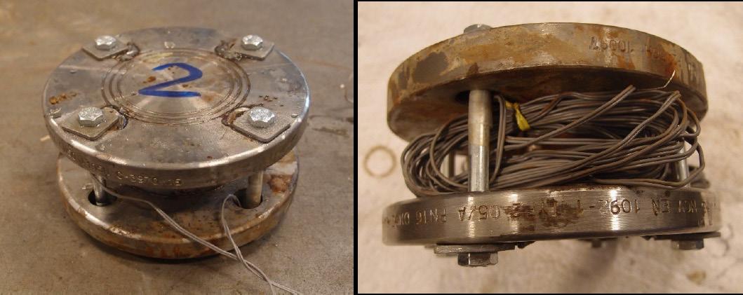
of the grout temperature. The temperature was recorded for 3 cycles. The air and grout temperature are shown in Figure 17-2.
Figure 17-2: Recorded temperature in air (blue) and grout (green).
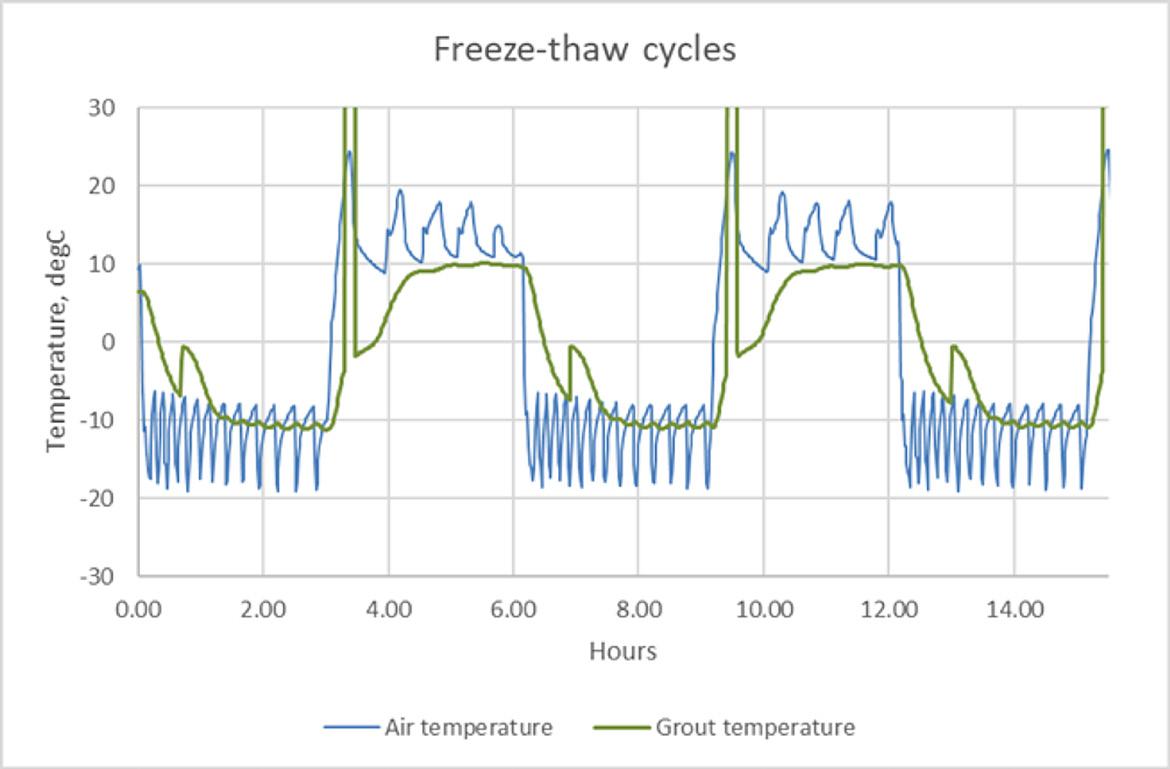
The temperature cycle was set to 3 hours of freezing and 3 hours of thawing (6 hours cycle). As shown in Figure 17-2, the grout temperature was recorded to be -10⁰C and +10⁰C for 1.5-2 hours for each cycle. The grout temperature shows a strange peak during freezing at ÷6 - ÷7⁰C and an even stranger peak during thawing at ÷4 - ÷2⁰C. The first peak can be caused by freezing of water below zero temperature under pressure (i.e ice formation), but the last peak must be caused by a measuring error (recorded temperature ⁓300⁰C, typically for short circuit for thermocouples).
When opening the molds after freezing and thawing,
the grout appeared to be intact. Marks could easily be made with fingernails as shown in Figure 17-3, left. The grout cylinders were squeezed out of the mold and observed visually. The grout was very weak and could easily be crumbled by the fingers as shown in Figure 17-4. The grout was significantly weaker than reference grout (cubes and drilled cylinders stored in water at SINTEF). The grout strength was not measured after freeze/thaw testing.
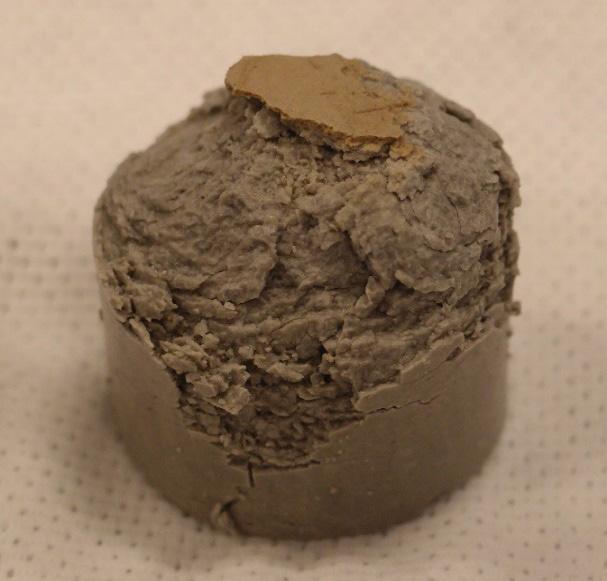
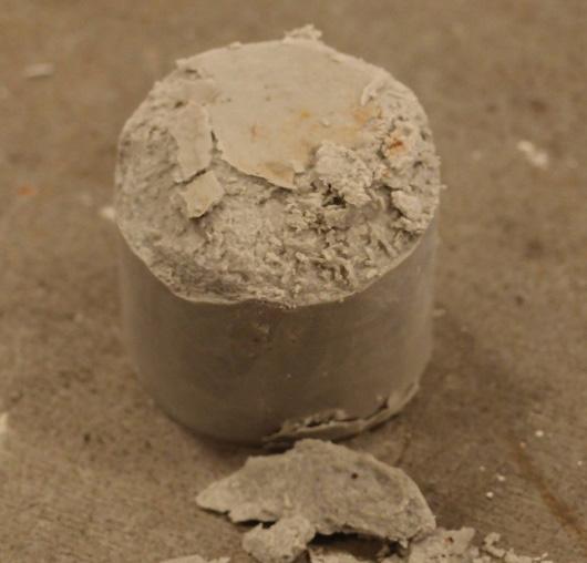
Two grout cylinders were placed in water after demolding. After two days in water, the cylinders more or less fell apart, and the grout structure seemed to be damaged by the freezing.
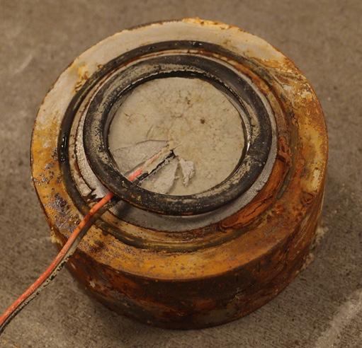
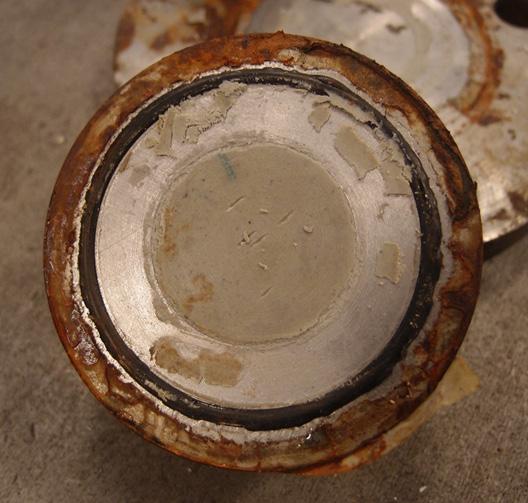
Surface strain gauges were glued on two bolts for each of the molds labelled 1, 2 and 3. Recorded strain for molds No 1 and No 3 are given in Figure 17-5 (freeze/thaw cycle 2-4). As can be seen from the figure, the recorded strain shows that the bolt was:
• contracting during the first half hour of the freezing period (until the grout reaches ⁓ ÷3⁰C)
• elongating from 0.5 until 1 hour
• stable from 1 until 3 hours
The bolt length returned rapidly to the original position when the grout was thawed.
Figure 17-5: Recorded strain by surface gauges on two bolts for Mold No 1.
For calculation of the load (F) and stress (σ), from the grout on the steel lid, we have used
• average recorded strain difference for two bolts, ΔƐ, in ‰
• effective bolt area 36.6 mm2 x 4 for 4 bolts, Ab = 146.4 mm2
• Steel E-modulus, E = 210 000 N/mm2
• grout sample cross section, AG = 1256 mm2
• Load, F = (ΔƐ E/1000) Ab
• Stress, σ = F/AG
The bolt elongation during freezing is slightly decreasing from cycle 2 till cycle 4. Calculated values for mold No 1 and No 3 are shown in Table 17-3.
Table 17-3: Induced force and stress when the grout is freezing.
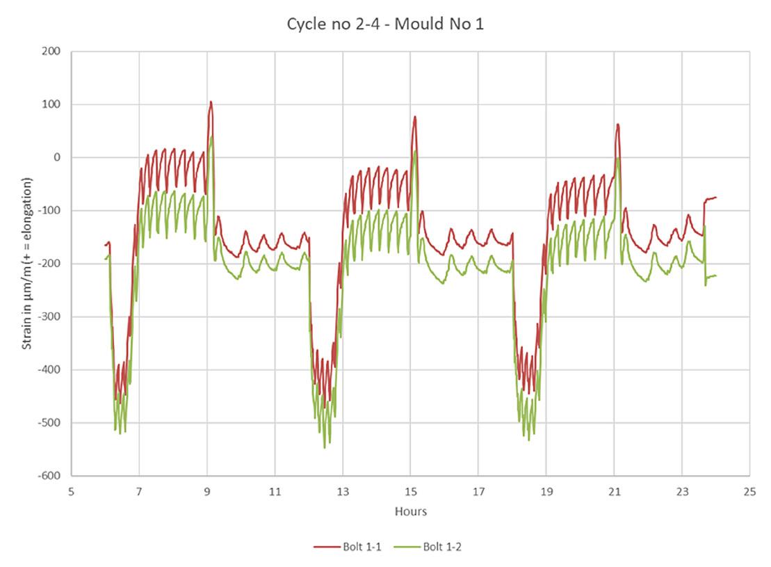
SINTEF received 2019-03-06 four Ø64 mm drilled cores labelled “CP 54 IB” and seven Ø64 mm drilled cores labelled “CP 54 CB”. These cores have been stored in water at SINTEF from arrival. From four of these cores, one 25/25/150 mm prism was prepared by sawing. Photo of the prisms is shown in Figure 17-6.
The prism initial length was measured by a ruler. The prisms were thereafter wrapped in thin plastic sheets to avoid moisture loss before exposure for 24 hours at -10⁰C. The prism length was then measured again in frozen state. The results are given in Table 17-4 below.
No cracking or other damages could be observed after the freezing exposure.
Prism No 1 2 3 4 Average
Expansion, mm/m 3.1 3.3 3.4 2.6 3.1
17-4: Prism length expansion during freezing.
Grout prisms prepared from drilled cores from the tunnel have been tested for expansion during freezing. The expansion was measured to 0.3 %, which is very low. A material consisting of 80 vol% water should expand more. It might be that the low expansion measured is somehow related to the bentonite content as water contained in very small pores may freeze at lower temperatures, but this phenomenon cannot be explained without further investigation.
The freeze/thaw experiments in steel molds show that, even if the expansion is low, the grout generated a considerable pressure on the steel lids during freezing. Surface gauges attached to the steel bolts connecting the upper and lower lids, showed a load corresponding to 10-14 MPa pressure from the grout on the lids.
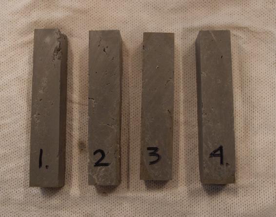
The grout was inspected after 1, 4, 12 and 24 freeze/ thaw cycles, respectively. When opening the molds, the grout seemed to be intact, but when the grout was pressed out from the steel cylinders it could be observed that the grout very easily could be crushed by the fingers. It was not attempted to measure the strength.
This means that when the grout is frozen in a complete confined state, the freezing generates a considerable internal pressure and a structural degradation of the grout.
Despite the fact that two different parties did similar tests and achieved the same results, remained still the question why the grout does not expand more, when it should theoretically expand 6-7% due to the water content. Therefore, did Bane NOR decide to run a big scale test at the frost laboratory at SINTEF. Two different setups were done, model A represented a completely filled ring gap, while model B was partly filled with backfill grout and water.
The SINTEF frost laboratory was constructed in 2009 and comprises of two rooms divided by a granite wall, placed in a confined and insulated space to avoid disturbance from the surroundings, as illustrated in Figure 17-7. The total floor area is 3.2 x 2.4 x 7.9 meters with insulated floor, walls, and roof, where the granite wall is 1.5 meters thick. The granite wall comprises of 12 granite blocks and each block measures 0.8 x 0.8 x 1.5 meters. One room represents the rock side, while the other room represents the tunnel side. Each room has an independent cooling unit and a control system for individual adjustment of the temperature in each of the two rooms. The purpose of the rock side room is maintaining a temperature representing the temperature in the rock mass, which often is 4-8°C in Norway. The temperature can be regulated as needed. The room also has the important function of supplying water to the rock mass through predrilled holes in the rock wall as well as being the technical room, hosting computers that collect the measurement data.
Figure 17-7: 3D model of the freezing laboratory.
Inside the granite wall, temperature gauges are installed, as illustrated in Figure 17-8. The temperature gauges are installed in slots at the interface between rock blocks and are distributed at seven depths in the rock, with closer spacing towards the tunnel side. Each slot is equally configured with temperature gauges, except for the upper four rock blocks, resulting in 56 points of measurement. In the four topmost blocks there are only 4 points of measurement. The total number of points for temperature measurements in the rock wall is 60. For the present laboratory setup, the data from two sets with measurements in 7 depths was utilized (14 points of measurements). The points of temperature measurement are located in the rock right behind the laboratory model that is custom-built for this experiment.
The granite wall has a number of horizontal penetrating holes with 20 mm diameter that can transport water from the rock side to the tunnel side, simulating water bearing fractures. One of the
Figure 17-8: 3D model showing placement of temperature gauges in the granite wall in red.
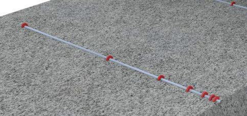
important elements in this full-scale laboratory experiment was the possibility of presence of water. The model was made watertight by sealing all joints in the model with Tec7. The granite wall beyond the laboratory model has 11 horizontal penetrating holes that can transport water into the model.
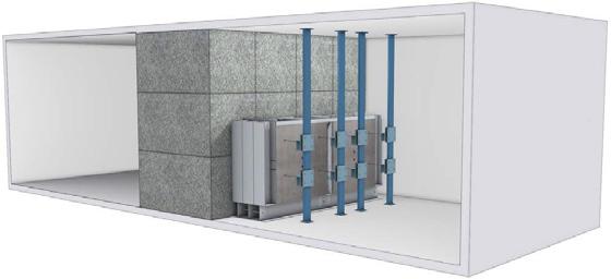
The room is equipped with a cooling unit, that can generate up to -20°C and +10°C. As the thermal conductivity in the rock mass is relatively low, it is important to introduce the wanted baseline rock mass temperature in both the rock side and the tunnel side at an early stage, letting the temperature in the granite wall stabilize at the wanted rock temperature. At experimental start-up, the temperature at the tunnel side was lowered to the designated experiment temperature.
In this experiment, the temperature was set to 8°C in both the rock side and the tunnel side on January 16th, 2020.
Figure 17-9: Principle drawing of the experimental setup for freezing of backfill grout.
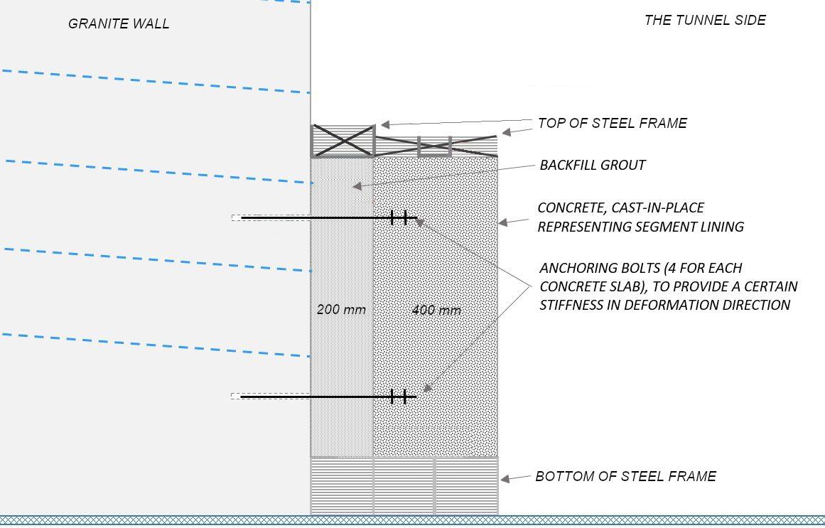
The target temperatures for the freezing exposure during the test were defined as follows:
• Temperature at the concrete surface: -15 oC
• Temperature at interface between concrete and backfill grout: -10 oC
The intention of this freezing testing was to reproduce the freezing exposure in the lining structure
as close as possible to the stated design freezing parameters.
Figure 17-10 presents the temperatures in the rock room, tunnel room, and at the concrete surface during the freezing cycle. The room temperatures were measured in cans with approximately 1 liter of water on the rock side and 0.7 liter of antifreeze solution.
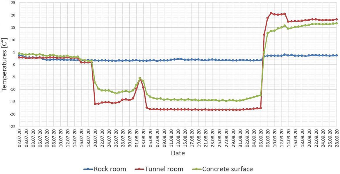
With the given dimensions of the rock mass in the model (1,5 m thickness) and total thickness of the lining structure, one would need to apply a temperature of 2 degrees for more than 3 months as well as assuring that no sources of heat loss were present.
A thermal load of -15 oC at the lining surface and +2 oC on the rock mass side at 1,5 m depth in the rock mass was applied. Under ideal conditions with no sources of “false” heat flow, such as leaking water through the model or insufficient or damaged insulation, the desired thermal profile could be achieved in approximately 25 days. This is based on the precondition that the entire model had a homogenous temperature of +2 oC at the start freezing cycle with -15 oC on the lining surface.
Thermal profiles measured at intervals are shown in the cross section of the freezing model in Figure 17-11.
There was a period of four days (July 31st to August 3rd), during which the freezing generator broke down and needed to be maintained. This delayed the freezing process, but it did not cause any detrimental effects to the physical experiment, as the room temperature never became higher than 0 oC.
The displacement of the lining, caused by freezing, was measured as the movement of the concrete lining in the direction perpendicular to the rock mass surface during the freezing of the model. Cord extensometers at 8 different positions on the concrete lining surface were used for this purpose.
The results are shown in Figure 17-12. The period of freezing from 19.07.2020 to 03.09.2020 is clearly shown. When freezing was terminated, the measured displacements ranged from 3 to 5 mm. For completeness, the diagram includes a few days before the commencement of freezing as well as a few days of the thawing.
Figure 17-11: Measured temperatures in the rock mass and section A of the lining model, including the thawing period.
Figure 17-12: Measured displacements of the concrete lining during the period of the freezing of the model.
After the termination of the freezing cycle and the model had defrosted and sampling of backfill grout was performed, applying different drilling techniques. Some examples are shown in Figure 17-13.
Throughout this sampling period, it was ensured that the model was kept wet by maintaining the initial water supply.
After the samples had been collected from the two models, they were evaluated and specimens for compression strength were made for the samples. Due to cracking and degradation, it was not possible to extract specimens for compression strength and density for all the samples. In general, it was
1
2 & 3
4
observed that the quality of the cores from model B was much poorer than for model A. Table 17-5 present a subjective description of the core qualities and Table 17-6 shows compressive strength and density measurements.
Not possible to extract large pieces from model A or B. The grout itself was intact but the cores broke easily in planes in all directions.
All cores where fractured. It was possible to extract specimen for compressive strength for 6 out of 10 cores in model A, but only for 1 out of 10 cores from model B.
The cores were partly disintegrated with internal fractures. In some parts the grout had decomposed (claylike). In general cores from model A were better than cores from model B.
All cores where fractured. In general cores from model A were less fractured than cores from model B.
It was possible to extract specimen for compressive strength for 3 out of 3 cores in model A, but only for 1 out of 3 cores from model B.
Table 17-5: Qualitative description of cores.
Model A B
Sample
A1 A2 A5 A8 A9 A5B A1K A2K A3K B4 B1K
Diameter, mm 72 61 72 61 Height, mm 61 74 44 54 63 53 60 85 60 53 46 Density kg/ m3
Compressive strength, MPa
Single res. 1270 1250 1250 1270 1270 1300 1240 1280 1230 1220 1290
Average 1260 1270
Measured 2,8 2,7 2,6 2,3 2,9 2,3 2,8 3,2 1,7 2,1 2,2
Converted* 2,6 2,7 2,0 2,0 2,8 2,0 2,8 3,5 1,7 1,8 1,9
Average. 2,5 1,9
Table 17-6: Results from compressive strength and density testing.
Examination of grout cores, drilled after the freezing cycle, showed considerable grout degradation for parts of all cores. Other parts of some cores were intact, and for these cores test specimen for determination of compressive strength could be prepared. The compressive strength achieved was about 2.5 MPa for section A and 2 MPa for section B (cube strength after approximately 190 days). These are good results compared to testing of test prisms cast during the cast of the model (cube strength 3 MPa after 100 days of water curing). The remaining parts of the cores were dissolved into small parts, and some parts were even dissolved to a claylike consistency. The cores taken from section B were considerably more dissolved than the cores from section A.
The laboratory setup aimed at reproducing the water and freezing exposure to the backfill grout of the segmental lining in the Follo Line Tunnel. The goals were to identify possible detrimental effects regarding degradation of the backfilling material and measure potential displacements deformations caused by the freezing induced expansion of the grout.
One freezing cycle was carried out which could achieve an exposure close to the design requirements for the Follobanen project. At the interface between concrete and backfilling, a temperature of approximately -8 oC during the test was achieved. The design specification calls for a minimum temperature of -10 oC at this location. The exposure of the model was carried out with the specified design load of -15 oC applied to the segmental lining surface.
Displacement of the concrete lining in the model was monitored during the freezing. Freezing induced expansion in the range of 3 to 5 mm of the 200mm
thick backfilling in axial direction of the model was measured. A theoretical maximum displacement under complete freezing of all water in perfect confinement can theoretically be calculated to be 15 mm.
The test shows less freezing induced deformations than the theoretical maximum. Clear signs of degradation of the backfill grout were found, even after only one freeze-thaw cycle. One must also bear in mind that the test does not account for the effects of significant inhomogeneities such as voids and channels. Based on the test results, freezing exposure with several repeated cycles over many years, is likely to gradually lead to a degradation of the backfilling.
The big scale freezing test has, like the small-scale freezing tests, verified that the expansion of the backfill grout during freezing is considerably lower compared to the theoretical expected once due to the water content.
For the calculation of the theoretically maximum displacement the following conditions were assumed:
• Maximum volumetric expansion of water during freezing: 9%
• Porosity of the backfill grout: 83%
• Degree of water saturation: 100%
• Expansion possibility in vertical direction: None (or very little due to the confinement)
• Direction of freezing expansion: entirely in axial direction of the model
With a thickness of the backfilling of 200 mm, one can therefore assess the theoretical maximum deformation in axial direction of the concrete lining D as follows:
D = 200mm * 0,83*0,09 = 14,9 mm
Hence, the measured displacements (between 3 and 5 mm) correspond to a range of 20 to 33 % of the theoretically maximum possible displacement in this model.
According to the project team’sevaluation, would the theoretical expected expansion of approx. 15mm imply a high risk of damages to the segmental lining, while the measured expansion can be taken by the segment ring without causing damages.
The registered degradation confirmed Bane NOR’s concern regarding the structural integrity because it increases the risk for potential washouts resulting in voids behind the lining. These voids increase the amount of water behind the lining, which not only represents a risk for leakages, but also would this water expand during freezing and could as such apply intolerable load to the segmental lining.
Therefore, has contact grouting been applied in areas for risk of freezing, in order to reduce potential leakage points, filling potential void and last but not least limit running water, which could washout degraded back fill grout.
Skjølsvold, Ola. Freeze-thaw testing of bicomponent backfill grout. Test report 2019. SINTEF Community
Strømvik, H. & Holter, K.G. & Skjølsvold, O. Freezing of backfill grout, laboratory setup and execution. Test report 2021. SINTEF Community
During TBM excavation, the segmental lining seemed to work well regarding watertightness. Only the grout ports were at this stage already a concern since the leakages occurred in some of the installed grout sockets. Injections with various types of resins did not lead to satisfying results either. AGJV finally
developed a packer, made of the same material as the gasket, which AGJV holds the patent of, as well. 100% watertightness could still not be achieved in all leaking grout ports, but the situation improved a lot with this packer and reduced the number of additional injections considerably.
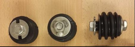
Once the water pressure built up behind the segmental lining, pressure up to 12 bars were registered, more leakages appeared in some of the locations. The Follo Line consist of approx. 36 km TBM tunnels with approx. 20 000 segment rings, summing up to approx. 1.700 km of installed gaskets.
The contract requirement regarding water tightness was rather strict:
Contractor shall ensure a dry tunnel, which permits damp spots with no visible signs of water remaining on a hand immediately after touching the spot. No dripping/visible flow of water is permitted whatsoever. In the event that such wet spots appear, whether through the joints between the segments or through the body of the segment, contractor shall propose and carry out remedial measures
After finalizing the TBM excavation, the contractor has performed various injections campaigns, mainly with local PU injections close to the leakage points by drilling through the segment body, but also to a minor degree with cement-based injection through the grout ports. By doing so, the total amount of water leakages through the segmental lining were
reduced to from approx. 15 l/s right after the TBM excavation to <2 l/s (which is below 0,1 l/m2/day for these tunnels) The dripping occurred from either the grout ports or from the joints between the segments. The injections were mainly performed sporadic, in areas where dripping was discovered.
Consequently, the total amount of water was, at least after various injection campaigns, not a big concern anymore, but the leakages could still not be accepted by Bane NOR, because the leakage water had a rather high pH value (> 11). Dripping alkaline water attacked installations in the tunnel made of aluminium. In order to avoid damages of the installed railway system equipment in the tunnel, client and contractor agreed that in the upper part of the tunnel profile, between 11 and 1 o’clock, above these sensitive installations, should be free of dripping points and the primary mitigation measure should be injections.
To avoid dripping in the remaining tunnel profile, AGJV in cooperation with his suppliers, developed a special rubber profile which diverted the water further down in the joint and into the drainage system via trenches at the slab.
Over various years, client and contractor discussed potential consequences of frost in combination with water leakages in the tunnel.
One concern was if the backfill material behind the segmental lining, which consists during installation of approx. 70% water, could expand during several frost sequences, and as such build up intolerable pressure to the segmental lining. Extensive testing in small scale, but also in bigger scale in a freezing chamber were performed, but no significant expansion was registered, and the project could rule out
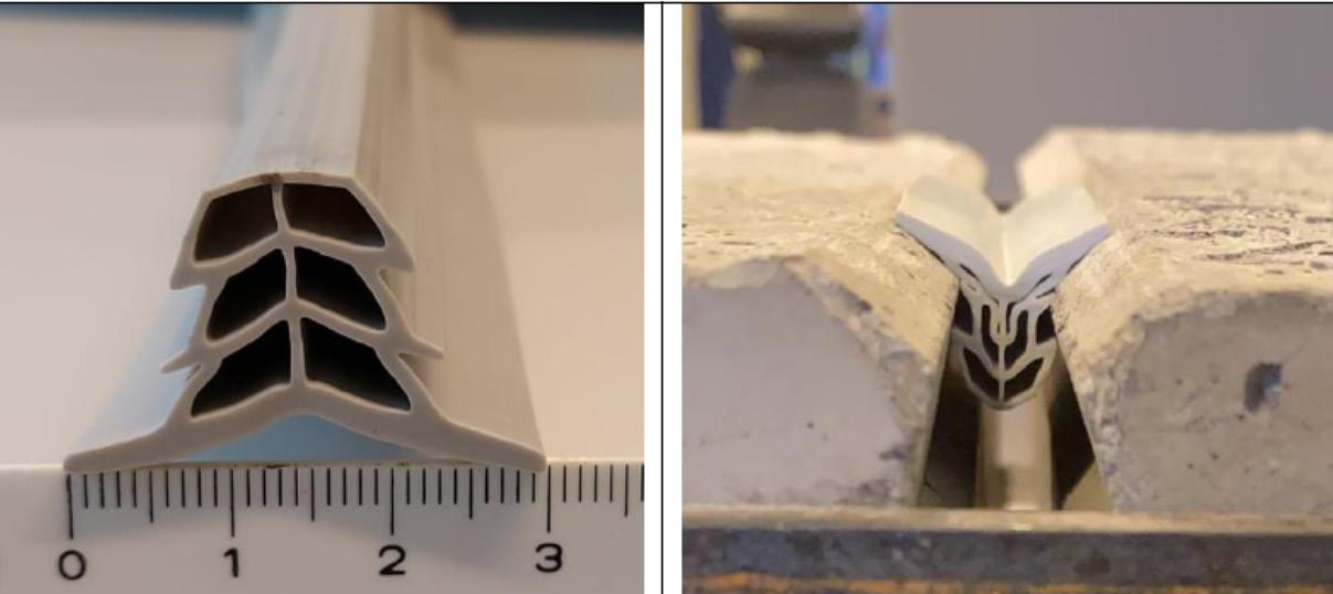
this risk. This is described in more details in chapter 11 b: “Backfill grout and freezing tests”
The second concern in regard with frost, was the building up of ice formations. During winter 2021, the outside temperature was below -10°C during various consecutive weeks and the frost came until approx. 5km into the tunnels. This resulted in massive ice formations in areas where post-injections had not been finalized yet, and also into areas that were not identified in the beginning as potential frost zones.
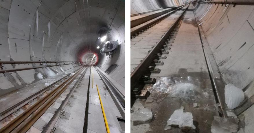
Under such conditions would a safe train operation not be possible anymore, and for the project it was clear, that a tunnel with this risk could not be handed over to the final operator. Therefore, another injection campaign was instructed by Bane NOR, with the goal to get the tunnels in the potential frost zones watertight. It was obvious that even very small leakages or nearly invisible dripping-points could result in ice formations in the tunnels. Such ice build-up can damage cables, hand-rails and other installations in the tunnel, or make unacceptable barriers on the walkway, which may result in dangerous conditions for evacuation.
SINTEF advised to perform a combination of systematic contact grouting and eventually injections of Colloidal Silica or PU between the rings where the contact grouting was performed, if needed. This advice was still under assessment when this article was written, but so far, the experiences from the systematic contact-grouting shows good results.
It was clear that the rubber profile could not be used in the frost zones, because the water would freeze in the trenches on the slab and create ice to be build up on the walkways. In the frost zones, all the leakages had to be stopped by injections.
Lessons learned – Important factors to be taken into consideration
In total, the design of the segments and the rings seems to be of good and suitable quality. The entire production sequence was efficient and worked very well. The rings were designed for high water pressure, more than twice the pressure that occurred around the rings after re-stabilization of the water pressure, but in spite of that, leakages occurred in some areas.
To avoid or limit leakages during TBM excavation of tunnels by using a singleshield lining and to avoid problems in potential frost zones, there are some important factors which should be taken into consideration for the planning and performance of the job:
• Stop, or limit the leakages by performing pregrouting during the excavation, in order to avoid outwash of backfill material and to reduce the water-pressure on the gaskets and grout ports afterwards
• The composition of the backfill material
• The stiffness of the gasket, the contract must allow for tailormade gaskets for the expected water-pressure in the different areas.
• Control of outwash of backfill material and routines for supplementary filling to avoid voids
behind the lining. Voids and incomplete filling may allow water to flow behind the lining and out through leaking-points. Some of the areas with incomplete filling of the bi-component were identified by echo-waves after the TBM excavation was finalized. These voids were filled by additional post-grouting. The contractual requirements for the backfill should be specified.
• Water, which has been in touch with the cement based grout, is very alkaline, with a high pHvalue. This water has an aggressive behaviour and may damage other components in the tunnel within short time
• Special attention should be payed to potential frost zones, in order to avoid leakages in those areas.
At an early planning phase of the project, it was decided to build the 20 km long Follo line tunnel with two separate tubes, instead of one doubletrack tunnel. This decision was made in close cooperation with the future maintenance organisation in Bane NOR and with the fire-brigade. The final choice of the tunnel concept was based on safety, better conditions for future maintenance, since one tube can be closed and the other still operated and a higher robustness for the future operation of the trains.
Cross-passages to connect the two tunnels are located every 500 meters in accordance with the TSI EN-50126. For long tunnels it is required to build rescue stations every 20th km. Since the Blix-tunnel (future name of the main Follo Line tunnel) is approx. 20 km long, it is not a strict requirement to build such a station. The four TBMs were assembled and operated from a rig area consisting of two approx. 450 m long tunnels with a big cavern at each end, approximately half-way along the 20 km long tunnel, which exactly suits the purpose of a rescue station as well. This system could easily be re-used as an efficient rescue-area for the operational phase.
Figure 19-1: Overview of emergency locations during the operational phase. The logistic area in the tunnel from the construction phase will be re-used as a rescue-area.
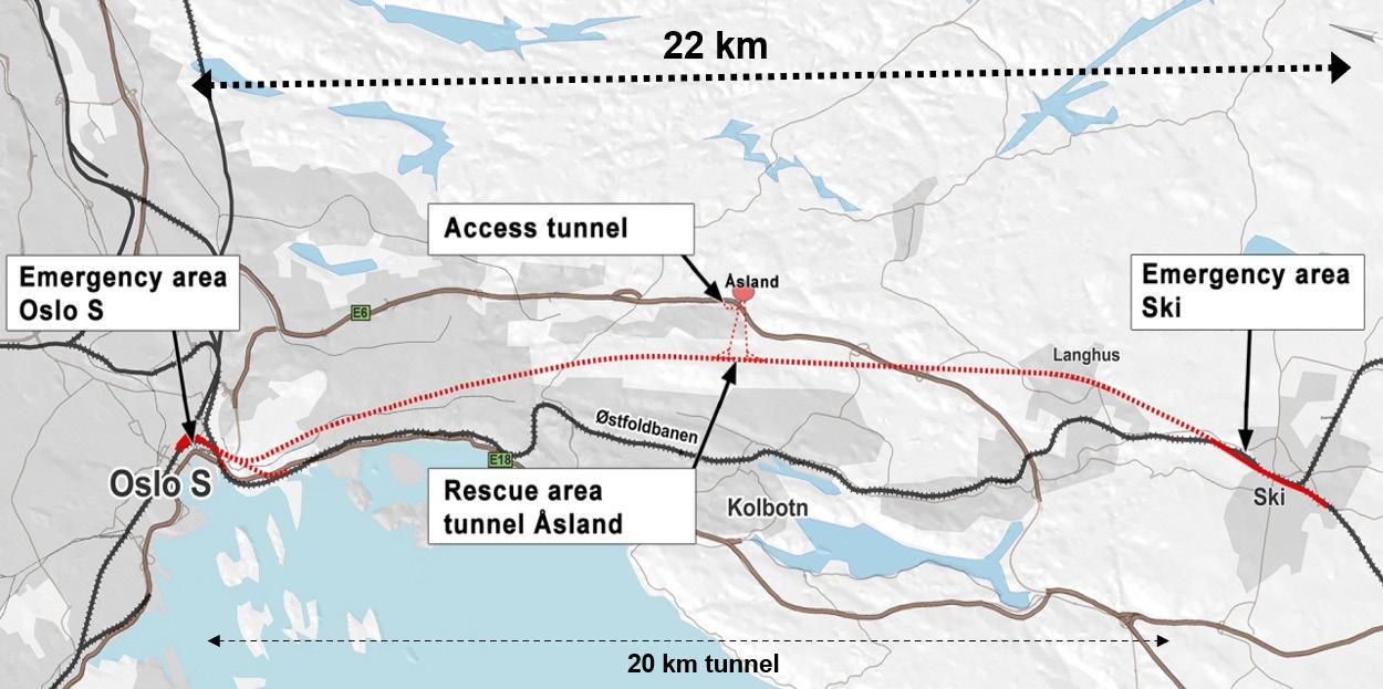
In case of a fire, the trains shall not stop if possible, but drive out of the tunnel. In some cases, this will not be doable, and the trains will have to stop in the tunnel. If this happens, they shall stop at the rescuearea tunnel, if possible. The last option is to stop in the tunnel and the passengers will have to use the cross-passages for evacuation to get into the safe tube parallel to the tube with fire.
The evacuation concept is based on self-evacuation by using the cross-passages to escape from the
affected tunnel over to the safe tunnel or other escape routes.
Between the two large assembly caverns, two 450 meters long tunnels, with a cross-section of approx. 115 m2 were excavated by drill and blast and used as a storage- and logistic-area during the TBMoperation. Between these two extended tunnels, five cross-connections were excavated. This is illustrated in figure 12-2 and 12-3.
The cross sections of the rescue area tunnels will be reduced by casting a permanent concrete wall dividing the cross-section in two parts, a future railway tunnel, and a parallel waiting-hall. A platform will be built along the wall, and smoke-tight fire doors leading from the platform into the waiting-hall will be installed.
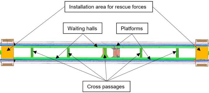
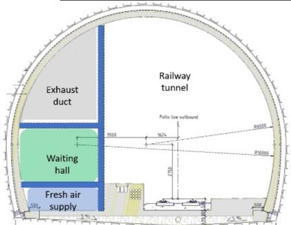
The five cross connections will connect this waiting hall to a similar waiting hall at the other railway tunnel. In case of a fire, the waiting halls will be ventilated with fresh air and act as safe areas. Passengers can either wait here until they are picked up by a train from the platform in the opposite tunnel, which is
not affected by the fire, or they can be evacuated from the waiting hall into the assembly cavern/ installation areas, and from there through the adit tunnel up to the surface.
From the respective assembly caverns, the two tunnels were excavated by TBMs, 9 km in the southern and northern direction. In the north, the two tunnels are connected to a 1.2 km long section where the tunnels were excavated by drill & blast as well as drill & split. These rock tunnels continue from the northern portal into a 600 m long cut & cover construction, which ends up at Oslo Central station.
Figure 19-2: An overview of the rescue area. Emergency routes are marked in green.
Figure 19-3: Rescue area tunnel, plan view and cross section.
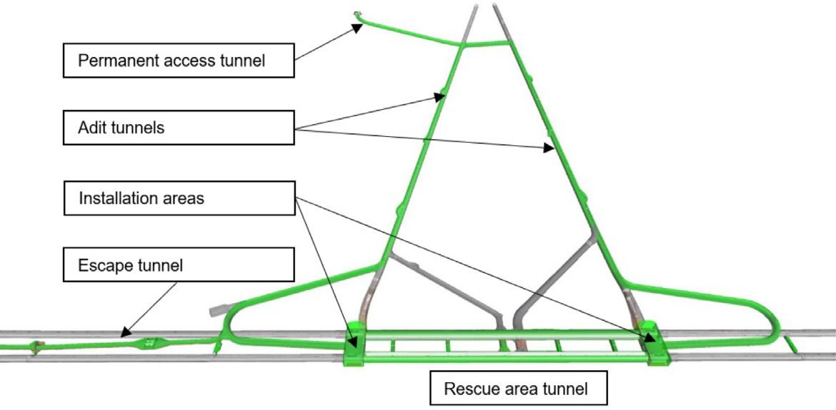
Cross connections in the area where the tunnels are crossing each other To fulfil all the requirements for the connection of the Follo-Line tracks to the different groups of tracks and platforms at Oslo Central station, the
tunnel with the inbound track is located on the left-hand side of the outbound tunnel in the northern part of the tunnel, which is in opposite to the Norwegian standard way of driving. To achieve this position of the tunnels in the northern part, the tun-
nels had to cross each other somewhere between the southern and northern portals of the tunnel. This tunnel crossing is known as one of the most special design elements of the Follo Line. This crossing takes place approximately 1.3 km north of the rescue area tunnel.
For the crossing, one of the tunnels was elevated approx. 5 m above the other. Because of strict requirements for the highspeed railway line, the inclination of the tunnel was limited to maximum 1.25%. The result of this is that the two tunnels are located at different levels over a section of 2.7 km. Two alternatives to create emergency ways were identified for the design of the tunnels to fulfil the
requirements for connections between the two tunnels every 500 meters:
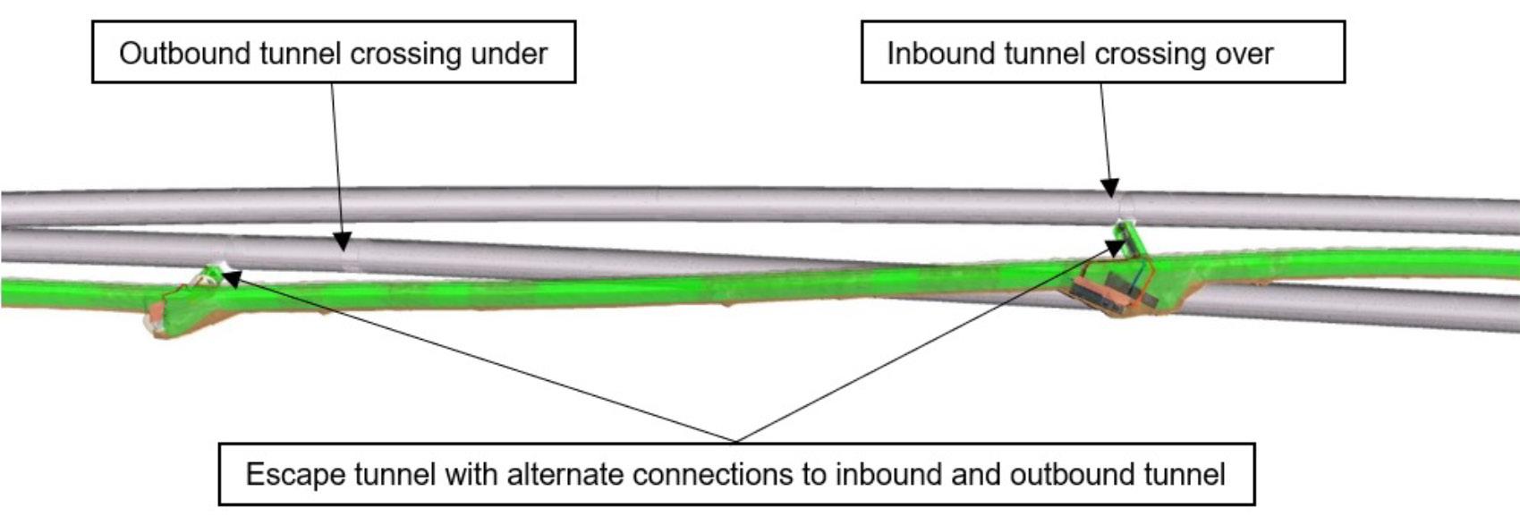
1. Cross connections could be built as vertical connections, with stairs for evacuation.
2. An escape tunnel, with an alignment going up and down, to connect with the tunnels at different levels, could be built between the two tunnels.
An escape tunnel, as described as alternative 2 was built by drill and blast excavation before the start-up of the TBMs. This escape tunnel served as emergency exit during the construction period as well. The concept is illustrated in figure 12-4 below.
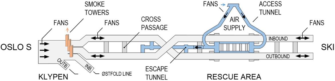
Figure 19-4: A section of the escape tunnel connections with different levels to the Follo Line tunnels at the crossing zone.
Bane NOR, who will also be responsible for the future maintenance of the tunnel with all the installations, established the goal to keep the maintenance cost low. The principle was “Need to have, not nice to have”. However, the various requirements
and demands on a new infrastructure constantly increase the amount of equipment. For example, the tunnel will have an internet connection which fulfils 5G standard and a ventilation system in the 20 km long tunnel was designed in close cooperation with the fire brigade.
Figure 19-5: An overview of the ventilation system with fresh air supply for the rescue area.
Longitudinal ventilation with two groups of jet fans are installed in the northern as well as in the southern end of the tunnels. Under normal circumstances, these fans will be switched off. They will only be used during maintenance in the tunnels and in case of a fire. The purpose of this ventilation is to control the migration of the smoke to secure a safe and smoke free evacuation route and safe access for the fire brigade.
The longitudinal ventilation shall be able to change the smoke direction in case of fire and create overpressure in the safe tube. The evacuation shall take place from the affected tunnel, through the cross connections towards the safe- and smoke free tunnel. A walkway is installed along the tracks which lead to the cross connections. Lights and signs illuminate the smoke tight green fire doors, which open into smoke free cross connections between the two tunnels.
In the northern part of the tunnel, within the cut-and-cover tunnel, the numbers of tunnels are extended and there are switches between the tracks, which require openings between the tunnels. In this area, the smoke will be controlled by three groups of extraction fans, which will extract the smoke from this part of the tunnel, and then prevent it to spread into the other tunnels unaffected by the fire.
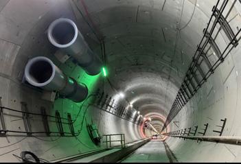
The rescue area, consisting of the waiting halls with access from the platform areas in the tunnels, the connection between these halls and the adit tunnels from the surface is built as a closed system. Ventilation, with fresh-air supply from the surface, will secure overpressure within this system. A safe and smoke free evacuation from a fire in one of the tunnels will then be possible.
The escape tunnel, described above, does have an airlock with axial fans to create overpressure as a safe environment. In case of a fire, the passengers will enter a safe and smoke free area as soon as they pass through the connections from the affected tunnel into this escape tunnel.
The Follo Line tunnels are not equipment with a fire water supply line, but in various meetings with the fire brigades it was agreed to provide fire water at the tunnel portals as well as in the rescue area in the middle of the tunnel. To compensate for these missing water pipes in the areas between the portals and the rescue area, a firefighting train, equipped with a smoke tight cabin and water supply, will be parked at Oslo Central station, which will be used by the fire brigade in case of a fire. The purpose is to make it possible for the fire brigade to handle the fire and, if necessary, give support to the evacuation of people. The longitudinal ventilation will contribute to control the smoke.
An important experience, from both the planning and construction phase of the project, is to involve the fire brigade who sit of all the experience handling fire event in an early stage and perform training session inside the tunnel. The fire brigade acted as an important contributor in all kind of considerations when it comes to emergency situations and even in the choice of the tunnel concept with two separate tunnel tubes.
Figure 19-6: Jet fans for longitudinal ventilation.
Later, it was commonly decided to minimize the number of fans for the longitudinal ventilation, with
Figure 19-7: The firefighting train.
installation in only three locations, the portal areas in addition to the closed ventilation system connected to the rescue area centrally located in the tunnel system.
Last, but not least, for future maintenance of the equipment in the tunnel, it is a good achievement for Bane NOR to have a limited number of water pipes to inspect and repair, instead of having water pipes through the entire tunnel. To give the fire brigade access to a firefighting train as a compensation, is evaluated as a better solution for the future.
TSI SRT (Technical Specification for Interoperability - Safety in Railway Tunnels) Commission regulation (EU) No 1303/ 2014. Chapter 4.2.1.5.2 “Access to the safe area”
The Follo Line project has adopted ISO 9001 Quality Management Systems - Requirements for quality management and complies with the environmental management standard ISO 14001 Environmental Management Systems - Specification with guidance.
Figure 13.1 demonstrates the pyramid with the main documents which define the process for the quality assurance in the Follo Line project.
The Contract Object shall meet the specified quality requirements including satisfying requirements for operational time of trains.
The project shall be completed within budget.
The project time was planned in accordance with the revised national budget of 2014, to be operational in 2021. This has been moved to 2022 due to unexpected occurrences.
The project must be carried out in accordance with project objectives so that the National Rail Administration’s reputation as a professional project developer and owner is strengthened. The project shall be completed without damage to surrounding structures and installations of third parties. The project should be executed with the minimum of negative disturbance to third parties (noise, pollution, mass transit on the road).
The quality plan defines responsibilities within the project, project management processes and describes how the project shall secure:
Figure 20-1: Quality assurance hierarchy.
The project steering document (PSD) is elaborated and describes Bane NOR’s role as project developer and owner at an overall level and the project task with associated goals.
The project has the following performance objectives, and they are given in order of priority:
The project is to be executed with the highest attention to health and safety of individuals.
The project is to be executed without damage to the external environment with restoration time over 10 years, without damage to cultural heritage and identified cultural area of interest as well as ensuring full compliance with permits granted by the authorities.
• Compliance with laws and regulations
• Compliance with building (construction) permits
• Project and Bane NOR’s management system requirements
• Achievement of all project goals set out in the PSD (performance targets)
• Quality control of deliveries from contractor
• Quality control of deliveries from consultants and subcontractors
• Compliance with other stakeholder requirements and expectations
The control plans provide a structure for the followup of contractor’s activities and establishes this in a set of control plans for each discipline. All plans have an owner and all activities in the plans must have one responsible person.
Control plans have been established in line with staff functions within each main area, such as engineering, procurement, construction, railway technology,
HSE, project control, etc.
The area manager is responsible for the respective control plan, including establishment, updating, and carrying out the various control activities in the control plan.
The control plans are continuously revised and updated as the works proceed.
The project is carrying out a set of systematic control methods to ensure that the products are according to requirements, and that processes used are appropriate and will lead to a satisfactory product.
Therefore, several methods have been used to complete these goals.
This is an independent review and verification of a process to ensure that the requirements are met. Audits can be performed both in relation to internal processes of client as well as contractor. The contract allows client to participate as an observer on all the audits that contractor is performing both internally and on its subcontractors.
Client is also doing its own audits of contractor in specific areas when required necessary.
The main principle is that audits are made in cases where the situation or issues within an area are unclear. Where the issues are known, other methods are more appropriate.
The individual area managers will identify needs, plans, , check on the various deliveries and processes that are under the individual areas of responsibility. The controls should be both process and product focused. The activities can consist of both verifications under Bane NOR’s own control and participation in controls performed by contractor. The controls must be verified in documented control plans.
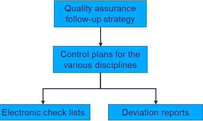
The Follo Line project’s overall verification and validation plan defines areas in which 3rd party verifications are required.
This should cover all the requirements for the project on independent controls in accordance with laws and regulations, and in accordance with Bane NOR’s own requirements.
In the Follo Line project a database completion system has been established, which is used to plan, record and log systematic checks and tests on deliveries in order to establish a detailed overview of the completion status. This is a very thorough process which ensures final controls of the product at a very detailed level
At the EPC Tunnel TBM project the above-described process is executed according to the illustration in figure 13-2. All details are defined in the quality assurance follow-up strategy document. Each discipline has outlined all follow-up activities with its responsible person as well as time intervals. For the follow-up at site, electronic check lists in OneNote have been established. They are also on tablet computers, so when inspections at site are performed, people are completing these checklists and can add photographic documentation to the lists. Since the system is online, direct communication with colleagues or their leader in the office can be obtained and immediate actions discussed, if required. If the structure / installation is not in accordance with the design a deviation report is written and communicated to contractor.
In addition to the internal electronic checklists and non-conformance reports, communication is established between client and contractor via WhatsApp messenger. This allows for direct communication regarding all activities on site, also inside the tunnel. The WhatsApp messenger app is used for sending notifications of quality controls, geological mapping, concreting and daily coordination. If non-conformance are observed during quality inspections, feedback to contractor can be given immediately and corrective measures can be initiated.
As described above, the control plan is an important tool for the quality follow-up. All relevant control activities for each discipline are defined in the various control plans, with corresponding control criteria and internal checklists. Control criteria can be requirements in Contract, laws and regulations, European and Norwegian standards, construction drawings and/or contractor’s own procedures and construction method statements.
Contractor is required to develop a quality plan and perform quality control for all works. Construction Method Statements (CMS) and Inspection and Test Plans (ITP) are submitted for all activities on site, and herein contractor describes how the works will be executed and which control activities will be carried out. In the ITP, test methods, frequency of control, type of control documentation and client’s role in contractor’s quality controls are described. For most activities, client assumes the role of observer and attends the controls on a spot check basis. For more critical operations, client can perform quality controls together with contractor’s quality inspectors or perform separate quality inspections.
Contractor’s ITP and quality inspections constitute a part of client’s control plans in terms of performing and documenting control activities, and it can be referred to contractor’s checklists and quality documentation to verify that the internal control plans are followed.
In the beginning of the project, client’s followup strategy was based on required spot checks. Contractor was by contract obliged to implement a quality management system which should be applicable to all aspects of the Work and part of the EPC concept is that the contractor maintains quality supervision of its own works. However, as the works proceeded, it became apparent that there were discrepancies between client’s expectations for the produced quality and achieved quality level in certain areas. During spot checks some quality non-conformances were identified by client, which had not been reported earlier, most likely due to lack of common understanding. As a result of this, a more frequent and hands-on quality control from client was introduced, with the aim of improving the quality of the final product and avoiding difficult contractual discussions at a later stage. Examples of extra quality activities include audits, separate quality and discipline meetings, frequent quality inspections at site and jointly quality inspections with contractor. The goal was to solve quality issues
quickly at discipline level and ensuring that only severe or repetitive quality issues would need to be brought up to management level.
Some examples from the quality control are described in Appendix II
The Follo Line project has introduced a systematic completion and test process through a database system. The process structures the activities related to the Mechanical Completion (MC) and Commissioning work, to ensure that client receive the contract object delivered on time, with required quality and functionality.
are:
• One common method of work, and one common system (PIMS CMS) for verifications and monitoring of completion and commissioning activities throughout the project.
• A continuously documented verification of the work, after construction, installation (MC) and functional testing (Commissioning).
• A complete overview of deficiencies (so called punch items), focuses on actions and responsibilities
• A complete overview of technical quality at “hand-over” to client for operations.
By using MC, a project is forced to complete several “quality milestones” before moving on to the next stage. For each quality milestone certain contractual requirements must be fulfilled. All installations will be followed up from engineering until completeness and it also takes care of safety issues and ownership trough all phases.
During the engineering phase a philosophy of how the completion and commissioning is going to be carried out inside an already established system split prior to contract award. Commissioning packages are created and linked to check lists and drawings. In many cases MC resources are coming from construction and will view the scope with other eyes than engineering, which will give the scope an extra quality check based on experience. MC is usually also checking drawings and documents across different disciplines.
MC is following up the production of equipment at the supplier’s factories. For special equipment, FAT (Factory Acceptance Test) and Mechanical Completion checks are done. This is done to ensure that the equipment fulfils the contract requirements, and that all faults and errors are identified and fixed
in the factory before shipping. MC secures the preservation at factory, shipping and at site to avoid risks for damages.
At site commissioning packages are defined. Contractor is calling for inspection when specific equipment has been installed, but before testing and commissioning. This is the first step. During this inspection, punch items are documented and categorised in A or B. All A items must be cleared before the specific system can go over to next phase RFC (Ready for Commissioning). When packages are in RFC status, commissioning can be performed. Before going to next phase RFO (Ready for Operation), all remaining punch items must be cleared as well. Under certain conditions, some B items can be transferred to operation. The figure below describes a Mechanical Completion process.
The name completion is somehow misleading and is making people think this process is done at the project end, which is clearly wrong. To get the quality on documentation of the entire production process, including equipment testing, it is important that MC
starts in the engineering phase.
Quality control in general is checking if the product is in accordance with the contract requirements. While quality control in the MC process is only one part of the documentation and verification, beside many other activities like scoping, punching and the various completion verifications, and last, but not least the documentation of the actual project completeness.
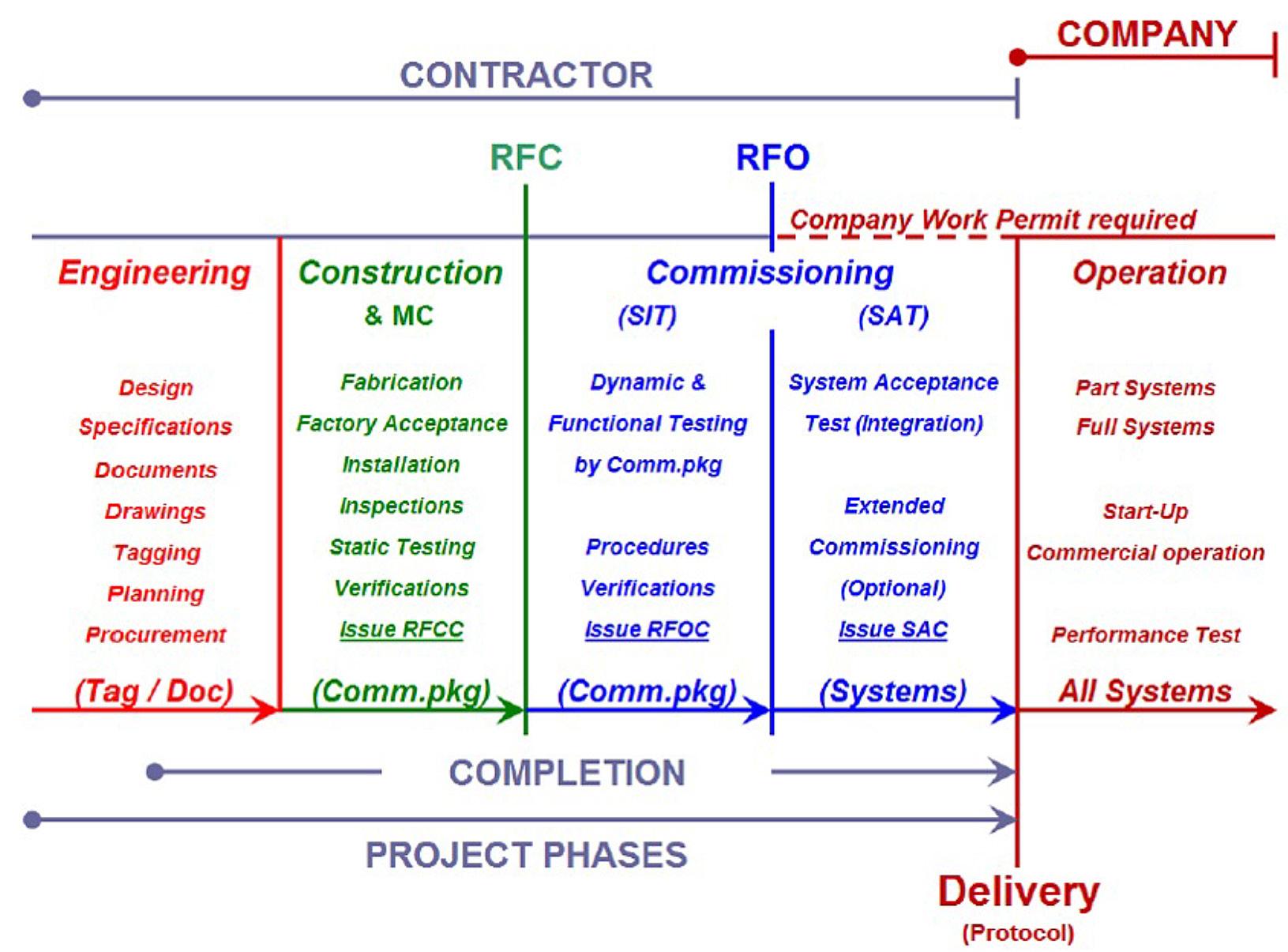
One of the main questions is, whether this rather heavy, costly, and time-consuming procedure is justified for the controls it provides?
By doing MC from the project start following the quality milestones, many errors and omissions will be discovered at the earliest possible stage. The later a problem is identified and corrected, the more costly will it become to repair.
Experience from The Follo Line project, and many other projects, has shown that the use of the MC process system, with qualified MC engineers, is
providing a complete project status, which helps to plan resources and the systematic documentation process, secures the required quality and functionality. In case of unexpected situations, like termination of contracts before finishing of works, the system provides an accurate overview of the project status, which was very helpful in the Follo Line project on the occasions when two of the main contracts of the project, EPC Tunnel D&B in the northern part of the tunnel and EPC Oslo S Civil, had to be terminated early in 2018.
It is generally challenging to maintain continuous high quality in construction projects since each project is unique. Industrial production has usually well-defined processes with execution under similar conditions. Construction projects are always at different locations with distinct boundary conditions, which makes it difficult to establish specific procedures in advance.
In an EPC contract with lump sums, the two parties’ understanding of the contract requirements are not always fully aligned. Contractor is often faced with a trade-off between efficiency/cost saving and quality, whilst the client expects the highest possible quality. “Sufficiently good”, “Fit for purpose” and “Highest possible” are subjective terms and leave room for interpretations. This room for interpretation can only be minimized by specific and detailed requirements in the Contract. In case this is not achieved, endless discussions at site may follow, leading to frustration and commercial discussions from both sides.
The environmental impact is continuously gaining importance in construction projects as well, and this can introduce further areas of discussion.
Bane NOR, as the project owner, considered it necessary to increase its own quality control during project execution, to secure the necessary quality and functionality, in order to satisfy the 100 years theoretical service lifetime.
UOS-00-A-90022 rev. 04E, 2018. «Sentralt prosjektstyringsdokument for gjennomføringsfasen», internal Bane NOR document
UOS-00-Q-90024 rev. 02E, 2015. «Follobanens kvalitetsplan», internal Bane NOR document
UOS-00-Q-90021 rev. 01E, 2015. «Overordnet verifikasjons- og valideringsplan», internal Bane NOR document
UFB-00-Q-00004 rev. 01E, 2019. «FB Tunnel TBM Oppfølgingsstrategi for EPC kontrakten», internal Bane NOR document
UOS-00-A-90053, rev. 00B, 2014. “ Project Completion Requirements ”, internal Bane NOR document
The health effect on tunnel workers with TBM method have not been in much focus. Minor studies have been conducted in recent decades, so when the Follo Line project was going to use four TBMs for drilling the tunnels, the National Institute of Occupational health (STAMI) saw an opportunity to more thoroughly and to a greater extent be able to study what health benefits drilling with TBM could have. Earlier, STAMI had conducted a study in close cooperation with Bane NOR on the Ulrikken-tunnel project in Bergen. This tunnel was excavated by an open TBM. Now they saw the opportunity to do a similar study on a double shield TBM in The Follo Line project. They contacted Bane NOR, once again, and the idea of conducting this study was presented for the entrepreneur, Acciona Ghella Joint Venture (AGJV), which was more than happy to put their workers on the project at disposal for a study project in this area.
The study had a start-up in 2016, shortly after the start-up of the first TBMs and continued during the entire excavation period. The target group consisted of tunnel construction workers using the TBM technique. A reference group was recruited among other construction workers and administrative personnel, who were minimally/not exposed to dust.
It is raised above any doubts that conventional drill and blast of tunnels have in generations had negative health effects on tunnel workers. More technically advanced and more efficient methods for operation have been conducted through the years, but the environment in the tunnels is still a source to health problems for tunnel workers. The exposure and health effects among tunnel workers, operating the drill and blast methodology, were studied in Norway in the 1990’s and 2010-2011.
The study showed i.e. that a high proportion of active tunnel workers had chronic obstructive pulmonary disease (COPD). The high contamination in the work atmosphere could be a potential cause to the development of COPD. Other studies have also shown an increased occurrence of pulmonary diseases among tunnel workers and other construction workers connected to the “underground work”. By conventional drill and blast, the tunnel workers could be exposed to several chemical substances like dust, included α-quartz (crystalline silica), diesel exhaust, oil mist and nitrogen dioxide in a variating degree, and this exposure could have a negative
health effect in short- and long terms. (Ulvestad et al, 2001) Experiences and earlier studies have shown that the content of crystalline silica is a special problem since exposure in the bronchial tree and alveoli are suggested to cause obstructive lung changes and silicosis.
One of the main questions raised was whether excavation of tunnels by TBMs gives less exposure of respirable dust and crystalline silica for the workers than tunneling by drill and blast gives? Another question was whether the type of TBM had an influence of the degree of exposure or not.
TBM-excavation
Construction of tunnels with TBM as conducting method have been used in Norway earlier i.e., in connection with hydropower development, but it was little knowledge about which health effect this method has had on the tunnel workers, which was why STAMI saw the opportunity to achieve more knowledge on this conducting method. Since it would be four TBMs in operation on the Follo Line project at the same time, it would give a good starting point considering the big amount of people working underground, which gave a large basis of analysis.
The goals for the study were to:
• Study crystalline silica exposure for tunnelworkers during excavation by TBM.
• Study the pulmonary function and gas diffusion capacity of TBM workers during the period of the TBM-drilling.
• Study biomarkers in serum for lung inflammation
• Study the relationship between exposure and the measured power parameters
• Control the interrupting exposures like contamination from vehicles in the tunnel, nitrous gases, particles, oil mist from hydraulics and lubrication of machines.
In the health monitoring project on The Follo Line project the study goals were:
• The change in pulmonary function as a cause of exposure of dust from stones and quartz, with both bronchial effects and the lungs gas exchange ability.
• The change in the blood content of markers for changes in function in blood vessels and lung
tissue which can be “early detection” of diseases in the lungs and cardiovascular system.
• Nose cells inflammation regulations (which could be a parallel to the regulation of the lung cells) –Currently only for tests, with possibility to later apply for financial support for the analysis.
In the exposure project on The Follo Line project, the goals were:
• Contribute to control the exposure level, and based on series of measurements identify relevant mitigations which can be implemented during the project
• Get an overview over the workers exposure of dust, quartz, as well as particles with a rougher particle size which could have an effect for the exposure in alveoli (associated with cardiovascular effects and fibrosis risk) and the bronchi (associated with obstructive pulmonary effects as COPD)
• Use the series of measurements in the health database to find connections between the level of exposure and health effects.
A protocol was approved by Bane NOR, AGJV and Regional Ethics Committee (REK), and in addition to Bane NOR, AGJV and STAMI, Synergi Helse came in as collaborators to conduct the health surveys.
To be able to conduct the health surveys in a correct way, STAMI contributed with training for occupational health professionals from Synergi Helse, which was supposed to perform the health survey in action. Scientists from STAMI assisted the surveys conducted through the project period i.e., quality assurance of the samples. The samples that were collected in order to look at the health effect and exposure effect, were analyzed by STAMI (exposure samples). The blood samples were analyzed by Oslo University Hospital.
Statistical analysis was conducted by STAMI. The status in the project was reported regularly through the project period. The analysis of the health results is still ongoing, and both analysis and compilation of results are a meticulous and comprehensive laboriously work, which needs to be done carefully to be sure that the results are reliable. When the final results are presented, they will be reported to the client and the entrepreneurs. The outcome of the project will also give the basis for further preparation of scientific articles, both at a national and an international level. This work is ongoing directed by STAMI.
In order to establish the health effect on the tunnel workers, the participants performed a health examination, consisting of lung volume tests, spirometry, blood tests, and collection of nasal epitheliums.
Some chronic diseases and regular use of medication can influence the biomarkers. Information about chronic diseases and medication was obtained and registered by the questionnaire. This could include rheumatism, diabetes mellitus, known alcoholism/ drug abuse, chronic or acute inflammatory conditions and regular use of ASS, statins, or anti-inflammatory drugs. Since those mentioned parameters could have an impact on the results, the collected data from the affected participants were analyzed separately.
Information on earlier and present smoking habits were obtained by a questionnaire, and serum was analyzed for nicotine and cotinine. Body weight and height were measured, and the body mass index (BMI) was calculated and evaluated in the statistical analysis. Some of the chosen biomarkers can be influenced by physical activity, so the participants were asked about their level of physical activity as well.
In addition, background variables, and other relevant information of interest (ethnicity, work experience, education, respirable health), were recorded using a self–administered questionnaire.
The completeness of the answers was checked during the health examinations. Self-reported airway symptoms at present and during the last 12 months were also recorded.
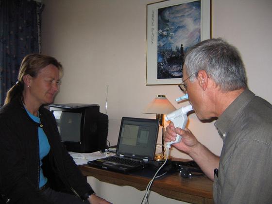
It was also conducted health checks through the entire excavation period, and after the excavation period was finished. These tests were supposed to be the basis, in order to analyze the health effect dust exposure have had. In total, there were conducted seven rounds with samples of the dust exposure effect. The sample equipment was carried by persons who worked different places on the TBMs and in the tunnels in general, Workers from all the four TBMs participated to cover any potential differences between the four machines.
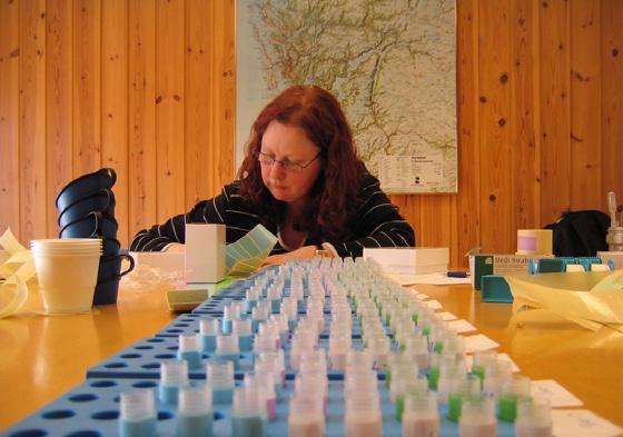
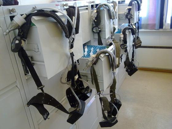
It appeared that it was a difference in the dust exposure, including crystalline silica, the tunnel workers were exposed for, based on where they worked at the TBMs and where in the tunnel, behind the TBMs, they were working. How much time the person spent in the different areas did also affect the exposure. Workers who worked in the area close to the cutterhead, i.e., changing the cutters, had a higher exposure than those who worked in the backup of the TBMs with i.e., extension of the process water pipeline. The longer time the persons spent in the different areas, the higher the exposure. For the persons who worked in the other parts of the tunnel, the exposure of dust was significantly lower than for the persons who worked on the front parts of the TMBs, close to the cutterhead.
It was also taken samples in areas where the workers were exposed by exhaust (diesel particles) and/or oil mist. The analysis of those samples showed that
the exposure was very low while working within the TBM-tunnels, compared with the exposures tunnelworkers are being exposed for by conventional drill and blast. This low exposure could be explained by the fact that the TBMs were electrical, and the transport of rock masses were performed by conveyor belt from the TBM and all the way out to surface. During conventional drill and blasts, the rock masses are transported out after the blasting by diesel driven wheel loaders and dumpers that creates a significantly portion of exhaust. In addition, the experience with this conventional wheel-based mass transport, is that it whirls the stone dust in the entire tunnel and along the transport routes all the way out to the deposit area. All the tunnel workers are exposed for this stone dust, and thereby the number of persons exposed by dust increases, not only those who works at the face.
At the same time as the sample taking was conducted, STAMI also considered what actions that could be implemented to reduce the dust exposure for all the workers during the project. Bane NOR, AGJV, Synergi Helse and STAMI worked together to find out and evaluate actions and barriers to reduce the exposure. Actions that were conducted during the project were:
• A “water curtain” behind the cutterheads
• Water mist sprayed on the rock on the conveyor belt on the TBM backup
• Mandatory and correct use of the dust masks while changing the cutters
• The use of solid one-off disposable suits while working inside the cutterhead
• Cleaning/ vacuuming the electrical cabinets, enclosures, centrals, etc. before conducting repair/ maintenance work
• Mandatory use of dust masks and gloves, i.e., for electricians who performs repair/maintenance work.
The effect of these actions appeared when comparing the samples taken before and after the actions were implemented. The results were also presented for all the involved workers within the different working areas of the TBMs and of the tunnel. They were informed about the unhealthy dust they could be exposed for by not performing the actions that were made, or by not using the mandatory protective equipment. This resulted in a higher degree of awareness and understanding among the workers for which negative effects the dust exposure could have, both in short and long terms.
Another element that contributed to a reduced negative exposure by dust, was drilling with a double shield TBM in combination with the installation of a single shield lining. The results from the study performed from the open TBM-excavation at the Ulriken tunnel project in Bergen, showed that the workers who performed the rock-support and shotcretework were exposed to higher levels of dust than any of the workers in the Follo Line tunnels were during the tunnel-excavation. On a double shield TBM, the concrete lining is mounted inside the shield at the same time in parallel with the drilling, and it is not necessary to conduct any securing work like rock support and/or additional shotcrete in the same way as needed when working with an open TBM.
The samples taken from the health examinations during the study are still being analyzed and the final results are not presented yet. It is therefore too early to make a final conclusion about the exact health effects drilling with TBM may have compared to excavating tunnels by conventional drill and blast. But for sure, based on the analysis results from the exposure samples that were taken and the actions that were performed through the project to reduce the exposure, a positive effect have been measured. The exposure of dust for the workers who operated close to the cutterhead were reduced.
The test results gathered during drilling with the TBMs showed a difference in dust exposure between different groups depending on where on the TBMs or in the tunnel they worked. The longer away from the cutterhead, the lower the exposure. An interesting observation, if you look at the dust exposure from an open TBM, like the one that performed the drilling for the Ulrikken-tunnel in Bergen, compared with the dust exposure from a double shield TBMs in The Follo Line project, the test results showed a lower dust exposure to all the workers working with the double shield TBM. This is probably because working with a double shield TBM, where the concrete lining is mounted during the drilling, the workers are in a lower degree exposed for the negative dust load which comes from the rock support and the shotcreting.
The results analyzed so far also demonstrated that drilling with TBM gave significantly less negative dust exposure from diesel exhaust and rock dust than are created from conventional drill and blast excavation. The main reason for this is related to the use of conveyor-belt for the transportation of the excavated material all the way from the TBMs to the surface. This gives less pollution from exhaust from vehicles and less dust whirled up by the wheels.
It is still great opportunities for the industry to reduce the health impact for tunnel workers by focusing on further development of technical solutions and barriers on TBM. It lies a big potential to reduce the negative health effect of dust, by using a larger amount of time on the organizational barriers like mapping dangers, looking at methods for work operations in different groups, i.e., maintenance staff. Finally; the awareness of each one of the workers, at all levels, knows what they can do to reduce the dust exposure in tunnel work.
Drilling with TBMs as operational system has come to stay, and therefore it is important and necessary that the industry take actions to do what they can to reduce the exposure the workers are exposed for, so the health issues and diseases caused by this exposure reduces as much as possible.
Some casting defects and non-conformance were observed during the production of concrete segments for the tunnel lining, many due to different understandings of the contractual requirements. The production took place in three factories on site, 24 hours a day, in order to provide continuous supply to the four TBMs that were operating.
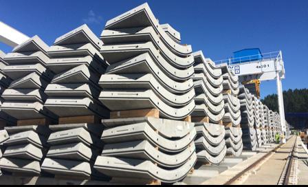
The non-conformances were mainly regarding the following categories:
• The appearance of bug-holes in some segments
• Gasket installation out of tolerances
• Casting defects (honeycombing etc.)
• Quality control procedures (acceptance criteria)
• Status and tracking
• High curing temperature
• Lack of reinforcement cover, mainly in the corner at the extra bar introduced to avoid spalling
Additional measures and preventive actions were taken to improve the quality of the segments, mostly in terms of increased quality control both during production, after demoulding, before loading on transport vehicles and after transportation into the tunnel. The tolerances for bug-holes and defects near the gasket were very strict, and defects could be hard to discover unless inspecting the segments closely. A colour classification system for the status of each segment (approved, rejected or for repair) was agreed between the parties, as well as the repair procedure. During segment inspections, misinterpretation of the acceptance criteria occurred regularly. Objective criteria’s for checking of segments were established. Another repetitive issue was insufficient repair works executed on the segments with defects.
Despite continuous work from both parties to resolve the quality issues, the discussions regarding quality of the segments were never properly closed. The different understanding of contract requirements from each party contributed to this. Numerous nonconformance reports were registered from 2017, when the topic was raised, until the production was finished. However, some of the same non-conformance found in the beginning of production were still observed at the end of the production.
In general, any consequences of undetected quality deviations in any tunnel project are difficult to predict. It is difficult to replace segments once they are installed in the tunnel, and any defects near gasket or on wet side are impossible to discover or repair after installation. The segmental lining is designed for service life of 100 years.
The tunnel segment factory layout was designed at an early stage in the project and was a part of the total layout of Åsland site. The layout was focused on logistics processes, with effective transport of elements out from the factories and directly into stacks of one and a half tunnel rings in the storage area. The layout did not consider the possibility of large numbers of rejected or quarantined segments, and how to handle those. It was possible to put a side a small number of segments at the entrance of the pre-storage in the factories, but the space was limited. With the increasing number of quarantined and rejected segments, it became more and more difficult to physically separate them from approved segments. Even though if a space could be allocated, the physical movement of such segments was difficult due the constraint on crane moving capacity, as the cranes priority was to feed the MSVs taking segments to the tunnel.
It meant that physical storage of quarantined segments was not separated fully from accepted segments. Instead, it was implemented a system with spray paint to indicate if a segment was accepted, quarantined, or rejected. This system had however weaknesses, as status could be changed from for example “accepted” to “quarantine”, and in such cases, new marking could only be done when the quality team had time to locate the segment and make a new mark.
To keep track of status of segments, quality department maintained a system to register and maintain status of segments, and from this register lists of
segments were given to logistics, who would pick segments from those lists. A database segment tracking system was implemented in the project, which included handheld scanners to keep track of each segment. However, standard functionality of this system did not include any quality status functionality.
The main lessons learned:
• Layout of factory and storage area should include a plan for how to handle rejected and quarantined segments, including a dedicated storage area.
• Segment tracking system should include quality status functionality.
• Acceptance criteria discussions to be formally finalised as early as possible, thus limiting the number of quarantined segments.
The main problem which never fully could be solved, were the bug-holes that tended to appear below the gasket. A low slump concrete was used together with a cast-in gasket, and the air trapped under the gasket was very difficult to avoid.
Lessons learned from this is:
• In design, when choosing between cast-in gasket and glued gasket, the problem of trapping air below the gasket should be taken into consideration,
• The production process should, if possible, be planned with measures to avoid bigger amount of trapped air.
• If cast in gaskets to be applied, perform more tests, and achieve more knowledge about the real consequence of a bug-hole below the gasket (as there is pr today no satisfying technical explanation on the requirement)
• Repair procedures, including for bug-holes at the gasket, should be developed and agreed before segment production starts.
Contractor rejected approximately 1500 segments out of 141.000 units, due to the bug-hole close to the gasket problem. In addition, the visual control of such defects was a somewhat unprecise task, and subject to individual’s assessments.
Several quality issues occurred during installation of the main drainage system in the tunnel, both for the main drainpipe under the slab track and for connected lateral pipes collecting surface water.
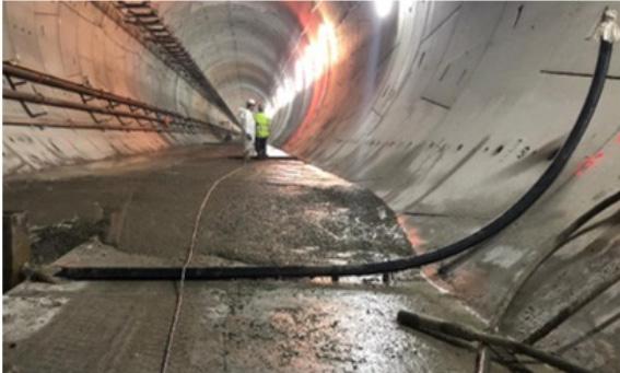
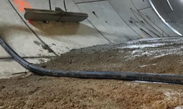
Every 80 meter there are lateral drainage pipes of diameter 75 mm, leading the excess surface water into the drainage system. The 75 mm pipes are cast into the invert slab, and the cast-in pipe was designed with a slope of 1% towards the manhole. However, the pipes were quite flexible, and the buoyancy of the empty pipe in the concrete provided some challenges on how to obtain an even and correct slope.
The initial procedure was to attach the pipe to the underlaying slab in two points. Some discussions took place regarding interval of fastening points for the main drainage pipe, but the smaller lateral pipes were not given the same level of attention. As the construction started, it was observed that the pipes were placed with wrong slope and bulging even before concreting. After concreting, the only way to control the actual built slope was by video inspection. However, this was not performed successively as the works proceeded in the tunnel, but it commenced after many kilometers of drainage were installed.
When video inspection finally was carried out, many of the lateral 75 mm pipes proved to have wrong slope and could not be accepted. Thus, the concrete had to be removed and the pipes replaced. For the remaining minority of pipes, the procedure was changed to obtain the correct slope after concreting.
Video inspection also uncovered quality issues for the main drainpipe. The main drainpipe is a corrugated double layer PE pipe of dimension 315 mm and is placed in a pre-cut channel in the invert segments before being cast-in by concrete. The pipe is located under the slab track and is transporting all water from the tunnel. The video inspections started while performing the drainage construction and revealed a substantial number of cracks, damages, and displaced joints throughout the tunnel. After video inspection commenced, corrective actions were taken which improved the frequency of imperfections in the pipes. This must have occurred during installation and concreting around the pipe, as the damages were not discovered before concreting. Leakage tests showed no leakages. Long-time consequences of these deviations are difficult to predict, but one outcome can be increased accumulation of sedimentation and lime deposits due to unevenness of the pipe. This again may lead to a demand for more frequent flushing and maintenance of the drainage system. In the frost zone, the main drain was isolated, but the isolation is not watertight, so cracks in the pipe and displaced joints can cause problems if water eventually enter the surrounding concrete, and cause damages when freezing. In the frost zone, leakage tests and video inspections were performed, and no fractures or other kinds of damages of the pipes were identified. The point is that it is important to have a specific focus on quality in the frost zone, and make sure that leakages will not occur in this area.
There have been other incidents as well regarding the drainage, such as concrete spill in the drainage and grout blocking drainage pipes. This has been identified and solved.
The lesson learned from these incidents is that a more rigid pipe for similar construction activities in the future shall be considered. By doing video spot
checks at various stages during construction, such deviations can be spotted early, and construction procedures can be changed as required.
The tracks in the tunnel are ballastless tracks, where a system with bi-block sleepers cast in a concrete slab has been applied. The slab track is executed as a continuous operation of sleeper and track installation, surveying control and concreting, ongoing for 24 hours per day. As the sleepers are cast into a concrete slab, there is no room for adjustment of the sleeper position afterwards, and installation must be done correctly the first time. The concrete slab must also be executed correctly, with correct level and slope.
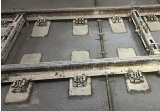
Before start-up of the slab track, there were several meetings regarding quality level and quality control of the works. A small mock-up was made to demonstrate the quality level of the concrete surface finish and to test the set-up of equipment, with which all parties were satisfied. However, when the actual works started, numerous unexpected quality issues occurred, many of them again due to a lack of common understanding of the requirements.
• Uncontrolled cracking of the concrete slab
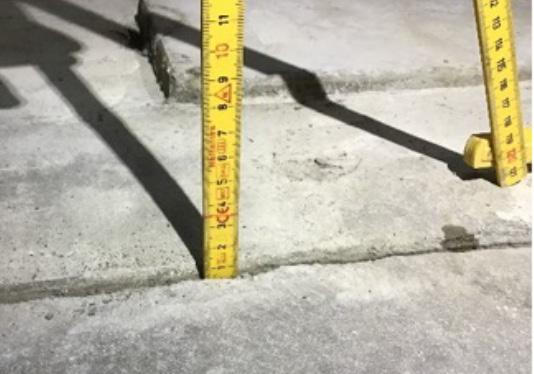
• Poor reinforcement cover
• Uneven and rough surface with depressions
• Excessive amount of water in the areas of concreting
• Too large sleeper spacing
• Spalling and other surface defects
• Trouble with clogging of the concrete pumping pipe
Since the operation was continuously proceeding, the quality issues needed to be solved promptly and preventive actions taken immediately. Extra quality meetings between client and contractor were held every week, and both parties intensified their quality control activities. Example of preventive actions taken on site are additional curing measures, changing the construction method for crack inducers, implementation of new procedures and equipment to remove excessive water and control measurement of spacing between all sleepers.
Due to the measures described, the obtained quality was clearly improved during the entire period when the slab-track was built.
The Norwegian Tunnelling Society have 1000 personal members, among those approximately 100 corporate members covering private sector, governmental agencies, research and education. Their representatives are active in the various permanent committees. One of these - The International Committee responsible for this publication - is specially supported by the core group presented below:
ANDERSENS MEK. VERKSTED A.S
P.O. Box 194, N-4401 FLEKKEFJORD
TEL. +47.38 32 04 20 FAX. +47.38 32 33 30
COWI AS
Grensevn. 88, N-0605 Oslo TEL.:+47.02694
EPIROC NORGE AS
Berghagan 7, N-1405 Langhus Tel: +4764860300
FOAMROX AS
Molandsveien 337, N-4849 Arendal Tel: +4791397732
GEOFROST AS
C.J.Hambros plass 2C, N-0164 Oslo Tel: +47 67147350
GHELLA S.P.A NUF
Sluttstykket 2, N-1291 OSLO
HERRENKNECHT AG NORWAY
Arnstein Arnebergs vei 30, N-1366 Lysaker Tel: +47 950 02 129
IMPLENIA NORGE AS
Fornebuveien 11, N-1366 Lysaker Tel: +47 22 50 73 00
LNS AS
N – 8484 Risøyhamn TEL +47 76 11 57 00 FAX +47 76 11 57 01
Supplier of tunnelling equipment and machinery to the international market. Shotcrete robots and computerised drill rigs. www.amv-as.no company@amv-as.no
Multidiscipline Consulting services firmapost@cowi.no www.cowi.no
Supplier of mining and rock excavation equipment and machinery epirocnorge@epiroc.com www.epiroc.com/en-no
Foamrox AS is a product development company specializing in fire, water and frost protection. post@foamrox.no www.foamrox.no
Specialized ground freezing company geofrost@geofrost.no www.geofrost.no
Contractor
Supplier of TBMs bengtsson.mats@herrenknecht.de www.herrenknecht.com
General contractor. Tunnelling Expertise. audun.aaland@implenia.no norway.implenia.com
General Contractors, Heavy construction. Underground engineering. firmapost@lns.no www.lns.no
MAPEI AS
Vallsetvn.6, N - 2120 SAGSTUA
TEL. +47.62 97 20 00 FAX. +47.62 97 20 99
MASTER BUILDERS SOLUTIONS NORWAY AS
Gullfotdalen 4, 2120 SAGSTUA
TEL +47 629 70 020
MULTICONSULT
P.O.Box 265 Skøyen, N – 0213 OSLO
TEL +47.21 58 00 00 Fax +47.21 58 00 01
NCC CONSTRUCTION
P.O. Box 93 Sentrum, N - 0663 OSLO TEL + 47.22 98 68 00 Fax + 47.22 89 68 01
NMC TERMONOVA OY
Torpmalmasvëgen 44, FI-10210 INGÅ
NORCONSULT AS
Vestfjordgt. 4, N - 1338 SANDVIKA
TEL. + 47.67 57 10 00 FAX. +47.67 54 45 76
NORMET NORWAY AS
Silovn. 20, NO-2100 Skarnes Tel. + 47 476 66 476
NORWEGIAN GEOTECHNICAL INSTITUTE NGI
P.O. Box 3930 Ullevål Hageby, N - 0806 OSLO TEL. +47.22 02 30 00 FAX. +47.22 23 04 48
ORICA NORWAY AS
P.O. Box 614, N - 3412 LIERMARKA
TEL. +47.22 31 70 00 FAX. +47.22 31 78 56
PROTAN AS
P.O. Box 420, N - 3002 DRAMMEN
TEL. +47.32 22 16 00 FAX. +47.32 22 17 00
SIGICOM AB
Götalandsvëgen 230, SE-125 44 ÄLVSÖ
Supplier of concrete additives for rock support and water control in tunnelling. post@mapei.no www.rescon.no
Supplier of concrete additives bestilling-no@mbcc-group.com www.master-builders-solutions.com/nn-no
Complete deliveries of consulting services. Energy, oil & gas, underground engineering. multiconsult@multiconsult.no www.multiconsult.no
General Contractors, Heavy construction. Underground engineering. firmapost@ncc.no www.ncc.no
Multi-Discipline Consulting and Engineering services. Underground facilities, geotechnical and rock engineering. company@norconsult.no www.norconsult.no
Supplier of tunnelling equipment and concrete additives
Consulting and engineering services. Geotechnical, geology, rock engineering. ngi@ngi.no www.ngi.no
Supplier of explosives and advanced charging systems. firmapost@orica.com www.orica.com
Intelligent tunnel ventilation, ducts, electronic tunnel tagging systems. protan@protan.no www.protan.com
SINTEF
Rock and Soil Mechanics
N - 7465 TRONDHEIM
TEL. +47.73 59 30 00 Fax. +47.73 59 33 50
SKANSKA NORWAY AS
P.O. Box 1175 Sentrum, N - 0107 OSLO
TEL. +47.40 00 64 00 FAX. +47.23 27 17 30
STATENS VEGVESEN, VEG DIR.
P.O. Box 8142 Dep, N-0033 OSLO
SWECO NORWAY AS
P.O. Box 400, N - 1327 LYSAKER
TEL. +47.67 12 80 00 FAX. +47.67 12 58 40
VEIDEKKE ENTREPRENØR AS
P.O. Box 504 Skøyen, N - 0214 OSLO
TEL. +47.21 05 50 00 FAX. +47.21 05 50 01
VIK ØRSTA AS
P.O. Box 194, N - 6151 ØRSTA
TEL. +47.70 04 70 00 FAX. +47.70 04 70 04
W. GIERTSEN TUNNEL AS
P.O. Box 78 Laksevåg, N - 5847 BERGEN
TEL. +47.55 94 30 30 FAX +47.55 94 31 15
Markaneset 24a, 5251 SØREIDGREND
Tel: +47 950 88 793
NORWEGIAN TUNNELLING SOCIETY
PO BOX 2752 Solli - 0204 OSLO Tel +47 98 21 05 30
Research and consulting services. info@civil.sintef.no www.sintef.no
General contractor. Tunnelling expertise. firmapost@skanska.no www.skanska.no
Norwegian Public Road Administration
Multidiscipline Consulting and engineering services. Hydropower, underground facilities, geotechnical and rock engineering. post@sweco.no www.sweco.no
General contractor. Tunnelling expertise. anlegg@veidekke.no www.veidekke.no
Supplier of rock support quality steel items e.g. the CT-bolt. post@orstagroup.com www.ct-bolt.com www.vikorsta.com
Waterproof lining in rock caverns and tunnels. Membranes for tunnels, shafts and rock galleries. tunnel@giertsen.no, hans.larsen@giertsen.no www.tunnelsealing.com
Network of Norwegian Companies for promoting commercial cooperation involving Norwegian underground knowledge and technology internationally. post@norwegiantunneling.no www.norwegiantunnelling.com
A leading national society with focus on rock engineering with governmental, private sector and individual members. nff@nff.no www.tunnel.no www.nff.no
Postboks 2752 – Solli, 0204 Oslo nff@nff.no | www.nff.no | www.tunnel.no
