9 minute read
19 Safety-concept for the operational phase

from Tunnelling in the Follo Line Project - NFF Norwegian Tunnelling Society publication no 29
by TunnelTalk
Anne Kathrine Kalager, Bane NOR Johannes Gollegger, Bane NOR
Introduction
Advertisement
At an early planning phase of the project, it was decided to build the 20 km long Follo line tunnel with two separate tubes, instead of one doubletrack tunnel. This decision was made in close cooperation with the future maintenance organisation in Bane NOR and with the fire-brigade. The final choice of the tunnel concept was based on safety, better conditions for future maintenance, since one tube can be closed and the other still operated and a higher robustness for the future operation of the trains. Cross-passages to connect the two tunnels are located every 500 meters in accordance with the TSI EN-50126. For long tunnels it is required to build rescue stations every 20th km. Since the Blix-tunnel (future name of the main Follo Line tunnel) is approx. 20 km long, it is not a strict requirement to build such a station. The four TBMs were assembled and operated from a rig area consisting of two approx. 450 m long tunnels with a big cavern at each end, approximately half-way along the 20 km long tunnel, which exactly suits the purpose of a rescue station as well. This system could easily be re-used as an efficient rescue-area for the operational phase.
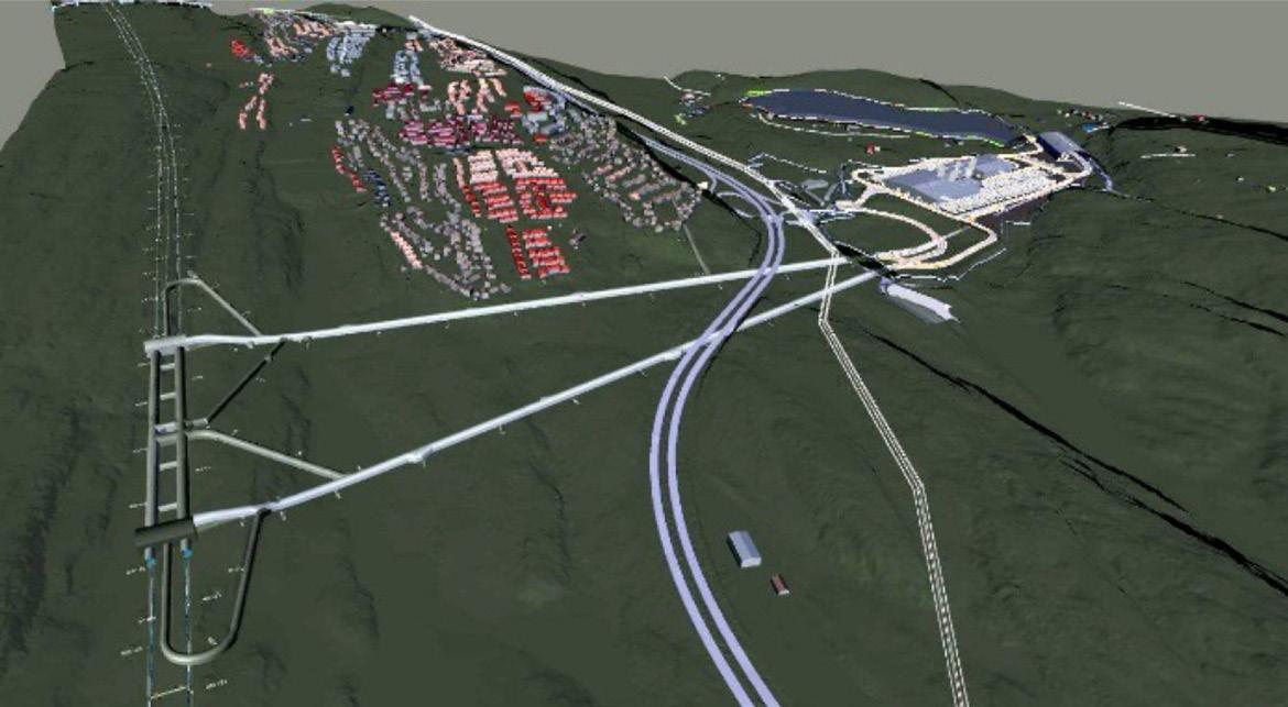
Figure 19-1: Overview of emergency locations during the operational phase. The logistic area in the tunnel from the construction phase will be re-used as a rescue-area.
In case of a fire, the trains shall not stop if possible, but drive out of the tunnel. In some cases, this will not be doable, and the trains will have to stop in the tunnel. If this happens, they shall stop at the rescuearea tunnel, if possible. The last option is to stop in the tunnel and the passengers will have to use the cross-passages for evacuation to get into the safe tube parallel to the tube with fire.
The evacuation concept is based on self-evacuation by using the cross-passages to escape from the affected tunnel over to the safe tunnel or other escape routes.
Design of the future rescue area
Between the two large assembly caverns, two 450 meters long tunnels, with a cross-section of approx. 115 m2 were excavated by drill and blast and used as a storage- and logistic-area during the TBMoperation. Between these two extended tunnels, five cross-connections were excavated. This is illustrated in figure 12-2 and 12-3.
The cross sections of the rescue area tunnels will be reduced by casting a permanent concrete wall dividing the cross-section in two parts, a future railway tunnel, and a parallel waiting-hall. A platform will be built along the wall, and smoke-tight fire doors leading from the platform into the waiting-hall will be installed.
The five cross connections will connect this waiting hall to a similar waiting hall at the other railway tunnel. In case of a fire, the waiting halls will be ventilated with fresh air and act as safe areas. Passengers can either wait here until they are picked up by a train from the platform in the opposite tunnel, which is not affected by the fire, or they can be evacuated from the waiting hall into the assembly cavern/ installation areas, and from there through the adit tunnel up to the surface.
From the respective assembly caverns, the two tunnels were excavated by TBMs, 9 km in the southern and northern direction. In the north, the two tunnels are connected to a 1.2 km long section where the tunnels were excavated by drill & blast as well as drill & split. These rock tunnels continue from the northern portal into a 600 m long cut & cover construction, which ends up at Oslo Central station.

Figure 19-2: An overview of the rescue area. Emergency routes are marked in green.

Figure 19-3: Rescue area tunnel, plan view and cross section.

Cross connections in the area where the tunnels are crossing each other
To fulfil all the requirements for the connection of the Follo-Line tracks to the different groups of tracks and platforms at Oslo Central station, the tunnel with the inbound track is located on the left-hand side of the outbound tunnel in the northern part of the tunnel, which is in opposite to the Norwegian standard way of driving. To achieve this position of the tunnels in the northern part, the tun-
nels had to cross each other somewhere between the southern and northern portals of the tunnel. This tunnel crossing is known as one of the most special design elements of the Follo Line. This crossing takes place approximately 1.3 km north of the rescue area tunnel.
For the crossing, one of the tunnels was elevated approx. 5 m above the other. Because of strict requirements for the highspeed railway line, the inclination of the tunnel was limited to maximum 1.25%. The result of this is that the two tunnels are located at different levels over a section of 2.7 km. Two alternatives to create emergency ways were identified for the design of the tunnels to fulfil the requirements for connections between the two tunnels every 500 meters:
1. Cross connections could be built as vertical connections, with stairs for evacuation. 2. An escape tunnel, with an alignment going up and down, to connect with the tunnels at different levels, could be built between the two tunnels.
An escape tunnel, as described as alternative 2 was built by drill and blast excavation before the start-up of the TBMs. This escape tunnel served as emergency exit during the construction period as well. The concept is illustrated in figure 12-4 below.

Figure 19-4: A section of the escape tunnel connections with different levels to the Follo Line tunnels at the crossing zone.
Ventilation concept
Bane NOR, who will also be responsible for the future maintenance of the tunnel with all the installations, established the goal to keep the maintenance cost low. The principle was “Need to have, not nice to have”. However, the various requirements and demands on a new infrastructure constantly increase the amount of equipment. For example, the tunnel will have an internet connection which fulfils 5G standard and a ventilation system in the 20 km long tunnel was designed in close cooperation with the fire brigade.

Figure 19-5: An overview of the ventilation system with fresh air supply for the rescue area.
Ventilation in the tunnel
Longitudinal ventilation with two groups of jet fans are installed in the northern as well as in the southern end of the tunnels. Under normal circumstances, these fans will be switched off. They will only be used during maintenance in the tunnels and in case of a fire. The purpose of this ventilation is to control the migration of the smoke to secure a safe and smoke free evacuation route and safe access for the fire brigade.
The longitudinal ventilation shall be able to change the smoke direction in case of fire and create overpressure in the safe tube. The evacuation shall take place from the affected tunnel, through the cross connections towards the safe- and smoke free tunnel. A walkway is installed along the tracks which lead to the cross connections. Lights and signs illuminate the smoke tight green fire doors, which open into smoke free cross connections between the two tunnels.
In the northern part of the tunnel, within the cut-and-cover tunnel, the numbers of tunnels are extended and there are switches between the tracks, which require openings between the tunnels. In this area, the smoke will be controlled by three groups of extraction fans, which will extract the smoke from this part of the tunnel, and then prevent it to spread into the other tunnels unaffected by the fire.

Figure 19-6: Jet fans for longitudinal ventilation.
Ventilation in the rescue area
The rescue area, consisting of the waiting halls with access from the platform areas in the tunnels, the connection between these halls and the adit tunnels from the surface is built as a closed system. Ventilation, with fresh-air supply from the surface, will secure overpressure within this system. A safe and smoke free evacuation from a fire in one of the tunnels will then be possible.
The escape tunnel, described above, does have an airlock with axial fans to create overpressure as a safe environment. In case of a fire, the passengers will enter a safe and smoke free area as soon as they pass through the connections from the affected tunnel into this escape tunnel.
Firewater
The Follo Line tunnels are not equipment with a fire water supply line, but in various meetings with the fire brigades it was agreed to provide fire water at the tunnel portals as well as in the rescue area in the middle of the tunnel. To compensate for these missing water pipes in the areas between the portals and the rescue area, a firefighting train, equipped with a smoke tight cabin and water supply, will be parked at Oslo Central station, which will be used by the fire brigade in case of a fire. The purpose is to make it possible for the fire brigade to handle the fire and, if necessary, give support to the evacuation of people. The longitudinal ventilation will contribute to control the smoke.
Lessons learned
An important experience, from both the planning and construction phase of the project, is to involve the fire brigade who sit of all the experience handling fire event in an early stage and perform training session inside the tunnel. The fire brigade acted as an important contributor in all kind of considerations when it comes to emergency situations and even in the choice of the tunnel concept with two separate tunnel tubes.
Later, it was commonly decided to minimize the number of fans for the longitudinal ventilation, with
Figure 19-7: The firefighting train.
installation in only three locations, the portal areas in addition to the closed ventilation system connected to the rescue area centrally located in the tunnel system.
Last, but not least, for future maintenance of the equipment in the tunnel, it is a good achievement for Bane NOR to have a limited number of water pipes to inspect and repair, instead of having water pipes through the entire tunnel. To give the fire brigade access to a firefighting train as a compensation, is evaluated as a better solution for the future.
References
TSI SRT (Technical Specification for Interoperability - Safety in Railway Tunnels) Commission regulation (EU) No 1303/ 2014. Chapter 4.2.1.5.2 “Access to the safe area”