


Though the decades, Italy has needed the technology to excavate long tunnels into unknown territory. Road and rail routes through the Alps to the north to link into Europe and connecting major cities to ports across the Apennines that divide its length demanded the determination to get through no matter the difficulties. Long water tunnels and more recently the development of metros beneath the streets of ancient, congested cities have tested the ingenuity of Italian tunnelling contractors and consultants and their equipment and machinery suppliers.
From the early 1980s Italy was the birthplace of new approaches to drill+blast and open face excavations through tectonically disturbed geology and extremes of deformation and groundwater ingress. Techniques to improve support and pre-support of the side walls and the face included introduction of the Premill machine, application of surfactants to support charge-hole and bolt-hole drilling, and the extensive use of Swellex rockbolts.
The 1980s and 1990s in Italy were also the decades of early TBM developments from application of and early Hydroshield to projects that combined Jarva rock TBMs with immediate support needs of rockbolts and shotcrete. TBMs used to drive pilot tunnels ahead of full profile enlargement became common practice for road and rail tunnels through ground of anticipated geological complexity.
Through these decades, Italian projects were the test beds of techniques, some that have since been discarded and others that
21 1985: Quenching Naples’ thirst by milking a mountain
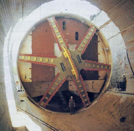
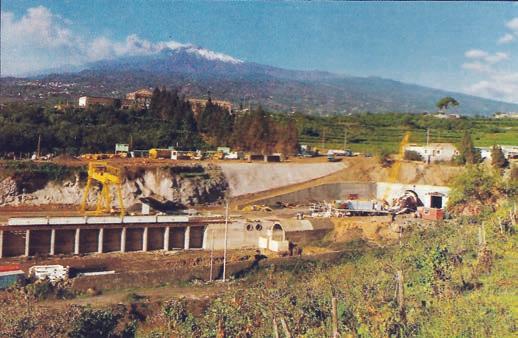
26 1990: TBM fit for Mount Etna
31


have given rise industry standards of today. Looking back on the projects of my site visit reports of that time reveal how Italy and Italian contractors contributed to the overall advancement of the tunnelling industry and how still today its projects are among those continuing a heritage of pushing the boundaries of the possible. n
Shani Wallis, TunnelTalk
CASE STUDY: Rail tunnels through the hills of the Valdarno Valley to complete a 44km missing section of the high-speed rail link between Rome and Florence presented contractors with largescale challenges. A change of alignment, a complete change in mythology for excavation and development of new support methods were all required to make completion of the project.
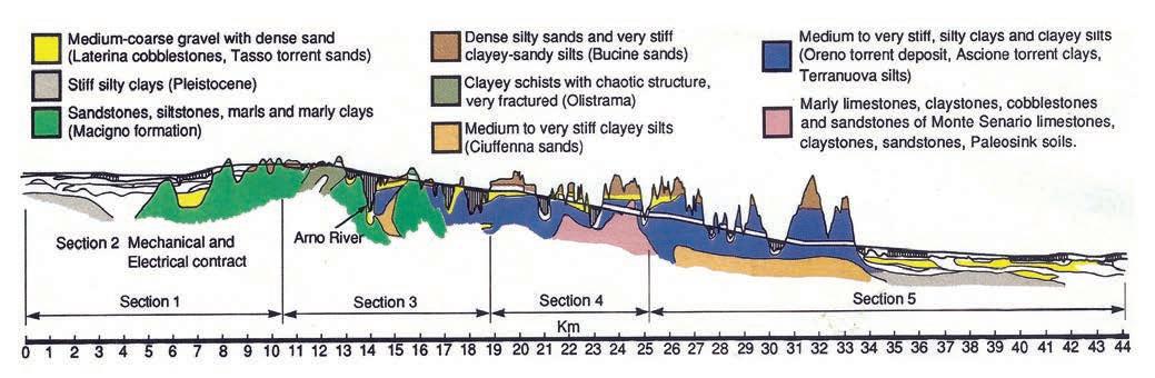
Whatever the plan of action, completing the last 44km on the Direttissima high-speed rail link between Rome and Florence was going to be difficult. The geology is highly variable, ranging from good quality sandstone to schists, silty shale interbeds, squeezing clays and waterbearing sands under an average head of 30m (Fig 2). But a decisive factor was past experience.
Work on this, the first high-speed rail link in Italy, started in the early 1970s. Much of the route is on the surface but, like all high-speed trains, Italy's Pendolino performs best on tracks with minimum gradients and gentler curves. To minimise gradients and curves, extensive tunnelling is required.
One of the first tunnels on the Rome- Florence line was the 90-120m2 San Donato Tunnel started in the mid1970s. For it, a deeper, longer alignment was chosen in expectation of meeting more stable geology and to avoid possible environmental and public opposition problems.
But excavation of the 11km-long tunnel through highly variable ground ran into costly and time-consuming difficulties. Unforeseen swelling clays, complicated by underlying waterbearing strata, required extensive
• Client: Ente Ferrovia dello Stato
• Consulting engineers: Ing C. Cassinis, Studio Geotecnico Stradate, Rome and Ing P. Lunardi, Rocksoil, Milan.
• Contractor: The Fe.S.P.I. consortium comprising: Carena; C.M.B.; Ing A Della Morte; Ing I Della Morte; Ing Guffanti & Co; Fondedile; Ing F Federici; Ferrocemento Costruzioni e Lavori Pubblici (Leader): Ing Provera e Carrassi; Torno; and Zecchina.
• Construction supervision: Il Unita per Progetti Speciali, Florence Direzione Centrale, Lavori 2a Commessa 6a, Florence. Departments of Ente Ferrovie dello Stato.
ground treatment. Floor heave was common and in one area the tunnel had to be remined because of excessive convergence. The tunnel took 15 years to complete.
When the San Donato Tunnel was completed and the new sections of track put into service in 1986, the 2hr 30min journey between Rome and Florence on a fast train on the old route was reduced to 1hr 50min on a high-speed train. This left only the 44km between Arezzo and Figline Valdarno, where the Pendolino has to leave the 250km/ hr Direttissima route and travel instead, at no more than 100km/hr, on the existing 60km of steep and winding
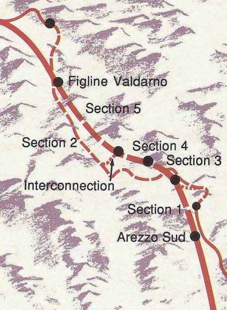
track. This adds some 25min and 16km to an otherwise 1hr 40min high-speed journey (Fig 1).
Upgrading this section to Direttissima standards has since become a matter of urgency to complete a 3hr 30min, highspeed 250km/hr link between Rome and Milan via Florence.
''The first alignment considered for the Arezzo and Figline Valdarno section was a single 14km-long tunnel under two valleys to create the shortest link between Val di Chiana and Valdarno", said Dott Ing Stefano Caldini of Ente Ferrovia della Stato. "The Adriana Tunnel, as it was named, would cross very different geology including carbonic anhydride deposits which are mined and used in local industry. These would not only be hazardous to tunnel miners, but also either extinguish or disrupt their use in industry. But it was really the San Donato experience which caused us to abandon the Adriana solution. Adriana is longer than San Donato and, likewise excavation was only possible from the two portals.
"As a result, the longer 44km-long alignment on the right side of the Arno River was adopted because it reduced the amount of tunnelling to 10km in 14 tunnels between 100m to 2,700m long, and some of these could be constructed artificially. This solution also allowed for the construction of an interconnection between the new line and the existing track. Such a link under the Adriana option would have been too difficult and expensive. Furthermore, the Arno solution allows a Direttissima link with the regional terminal in Arezzo", said Caldini.
The construction contract on a turnkey basis was awarded to the lowest of five bids at 714 billion lire (£330 million) in June 1983 to Fe.S.P.I., a consortium of 11 Italian contractors, with. Along the 44km length there are ten bored tunnels totalling 7.3km and 3.5km artificial tunnels within a 25km length; 20 viaducts totalling 17km; and 16.2km of cuttings and embankments (Fig 2). The contract also includes 8km of double track rail for the interconnection.
Although ground conditions would be similar in complexity to those in the San Donato Tunnel, several shorter tunnels were considered more appropriate than one longer tunnel for many reasons. According to discussions with Fe.S.P.I. engineers, there would be more points of attack and work could be expected to progress faster, a particularly important consideration in the relatively short five-year construction period. Also, building viaducts is generally cheaper, more straightforward and less prone to costly risk than tunnelling. In this case Fe.S.P.I. developed and
is using a new technique which allows it to erect a 25m section of precast viaduct/day.
Bored tunnels were said to be two or three times the cost of a viaduct, and ten to 15 times the cost of an embankment. Broadly speaking, a long single mined tunnel in softer ground in Italy could be expected to cost about 30 million lire (£12,000)/linear metre and about 20 million lire/m for artificial tunnels.
In addition, a viaduct over the intervening Arno River was expected by Fe.S.P.I. to be less problematic than tunnelling under it, despite the fact that this will be the highest rail bridge in Italy, and the second highest in Europe next to one on the Hannover-Würzburg line in Germany.
With Ferrocemento, a major Italian contractor with substantial tunnelling experience, as technical leader,
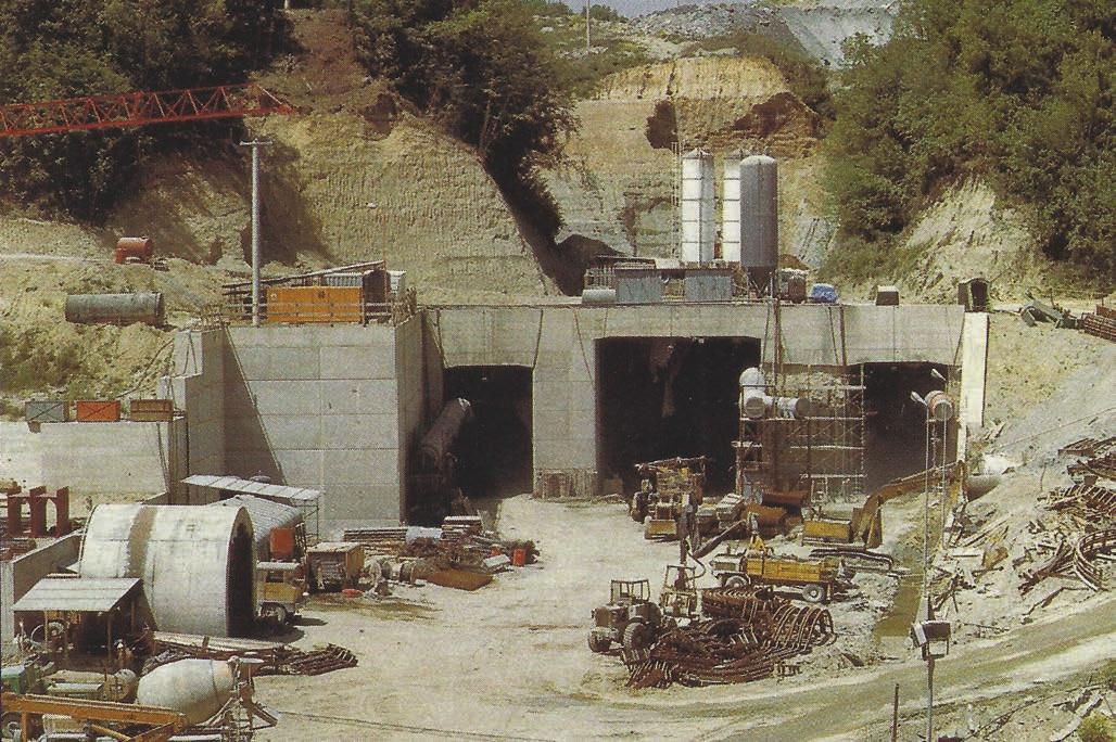
work on site began in September 1985 and tunnelling started at the end of 1986.
Extensive site investigations for the Arno alignment were carried out by Ferrovia in 1981-1982. After winning the contract, Fe.S.P.I. carried out extra, more detailed investigations which indicated that while as much as 80% of the tunnel work was expected to be in relatively stiff clay, extensive soil consolidation would be necessary in the sands and gravels of the shallower, shorter tunnels.
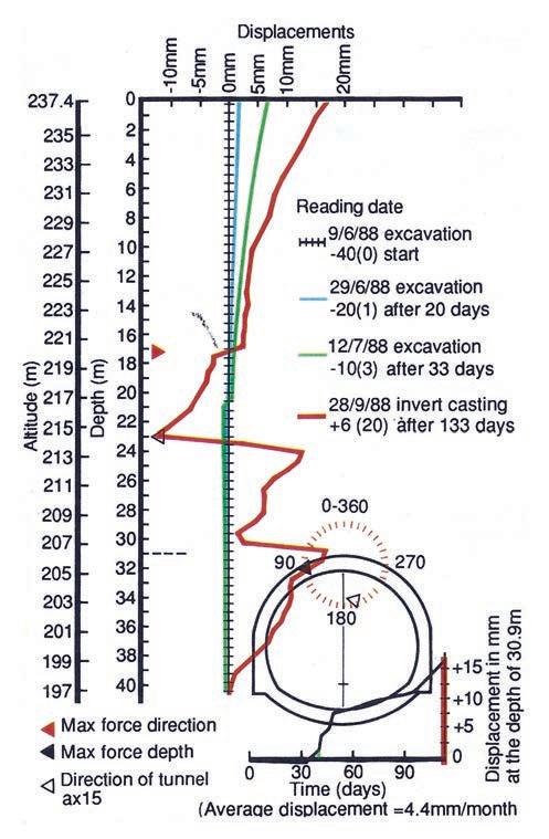
Roadheaders, which could be expected to produce high productivity in the stiff clay, were to be used on a top heading and bench programme. Immediate support would comprise shotcrete, wire mesh and steel arches. Following the principles of the Peck Observational Design Method (ODM), regular readings of comprehensive ground measurement instrumentation stations would ensure that adequate immediate and permanent support would be applied prior to casting the final concrete lining.
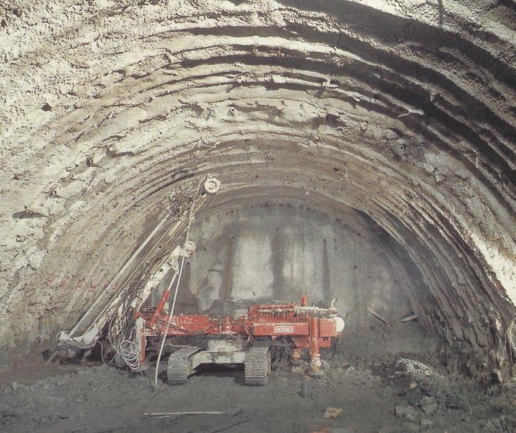
Unfortunately, like so many potentially difficult tunnelling projects, predicted conditions have proved more difficult than anticipated. "Although we knew quite well that there was a large amount of clay in the alignment, we expected it to be stiff," said Fe.S.P.I. "It was a big surprise to us to find that the clay contained many lenses of wet sand and that when excavated it behaved like a mattress or sponge. It is highly compressible. Not only was the large 80 tonne roadheader sinking into the invert, but the tunnel itself was sinking. This was evident from the readings taken from the in-situ measuring stations on the surface. Once, during excavation with a hydraulic ripper, the steel support arches immediately behind were vibrating and deflecting. These were conditions totally unforeseen,” they said. “Because of them we have had to change completely our original method of attack.
"One of the first things we did was widen the arch of the steel supports by extending the foot of the arch from 60cm to 1.3m. This gives the arch a larger supporting surface to limit face displacement. Then, after trying several times to employ the roadheader in the clay, it was absolutely clear that it was not possible.
"It was also clear that the clays in which the roadheaders were expected to operate would also require ground treatment. The emphasis of the work has moved from one of fast excavation without ground treatment to one of ground treatment with slower progress."
Rodio, Fondedile, Presspali and Geosud were engaged from the outset to carry out ground treatment for the work, and the original 100 billion lire subcontract has since increased to one of more than 200 billion lire.
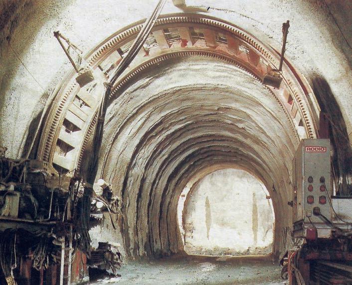
Under the revised plan, all excavation begins with comprehensive pre-support. In the poorest ground conditions, generally in the shorter, shallower tunnels, excavation follows the top heading and bench programme. The crown is spiled for 15m ahead with jet grouting as is the face of the 65m² top heading. A 1m maximum advance is then excavated and a doubled steel arch, totalling 40cm wide, is erected. This is anchored laterally with either prestressed anchors in the worst conditions; non-prestressed steel pipe with jet grouting in soft ground; or soil nails in medium ground. Soil nails, developed specifically for work on the Direttissima tunnels by Geosud, based on an idea of Prof. Giovanni Calabresi of Rome University, are 5m-long nails with a T profile 60mm high and 70mm wide which are statically fixed into the ground using a special rig. Once the top heading is through, and before benching starts, the feet of the top heading arches are supported by micro-piles or pillars of horizontal and vertical jet grouting. An in-situ concrete beam is then cast followed by a top heading insitu concrete arch. In shorter tunnels of less than 250m or so, the top heading is completed before benching starts. In tunnels of more than 250m, benching is concurrent and about 60m behind the top heading.
A 4-5m length of the 45m² bench is then excavated and supported and the in-situ concrete wall is cast. The invert is then undercut by about 1.5m and the concrete floor cast to close the permanent ring of support.
In better quality clay, generally in the central part of the longer tunnels where cover is greatest, the pre-cutting system of pre-support, introduced by Sipremec of France is being used. The hydraulically operated machine belongs to, and is provided by Rodio.
First, the big 4m-long chainsaw-like blade cuts an 18cmwide slot around the periphery of the full 110m² tunnel profile. Once a 1-3m length is cut, the blade is withdrawn and the 4m-deep slot is filled with dry mix shortcrete containing 40kg/m3 of steel fibre. When the full profile is cut and filled, the core is excavated and supported in
rounds of 1m to 3.5m before the pre-cutter goes to work once again. During pre-cutting, the invert of the previous round is cast. Consolidation of the face using fibre-glass tubes is carried out every three rounds.
"It takes about 16-24h to cut and fill a full doubletrack tunnel section," said Fe.S.P.I. "and we achieve about 12-15m/week with the system."
In zones where the full 110m2 section can be safely excavated, each cycle beginning with comprehensive pre-support of a 15m zone ahead of the face. The crown is first consolidated by jet grouting through 89mm o.d. Mannesmann steel pipes with pressures of up to 350 bar and the face stabilised by injecting grout at about 150 bar through fibre glass tubes. In particularly bad ground at shallow portal areas, jet grouting from the surface into the wall zones is also carried out.
Excavation of about 1m then follows by rippers and frontend loaders into dump trucks. A coupled steel arch is then erected and followed with a layer of wire mesh and up to 200mm of wet mix shotcrete.
Maximum 1m rounds are completed for about 10m or until about 3m from the end of the 15m pre-consolidated zone. An in-situ concrete invert is then cast before the next 15m round of consolidation begins. "It takes about one week, working 24hr, 5 days a week, to complete one 12m excavation cycle starting with consolidation," said Fe.S.P.I. Often, ground treatment is carried out during the weekends which allows five rounds or 60m to be completed in a month.
Rapid casting of the final in-situ lining is very important according to Fe.S.P.I., since "even in the better overconsolidated clays, the ground can only stand for a maximum 2-3 months without the final lining before unacceptable deformation or tunnel sinking occurs. In some areas, the tunnel has had to support up to 40 tonne/ m2 of clay load. Under such circumstances, the crown will squat and slumps of up to 15cm have been recorded. In other areas, the tunnel crown is very close to an interface with overlying waterbearing gravel, and the gravel has broken through many times."
In the top heading and benched tunnels, the top heading gets two cast linings - a 50cm-thick in-situ lining cast as part of the excavation cycle, followed by the outer 30cmthick final lining that finishes all the tunnels.
All the tunnels are also protected against any possible water ingress or seepage by a PVC lining behind the final lining. In the full-face consolidation and precut tunnels, the waterproof lining operation is about 100m behind the face with the final lining, which is systematically reinforced with arches on 1.75m-2m centres steel and double layer of wire mesh, being cast about 50m behind that.
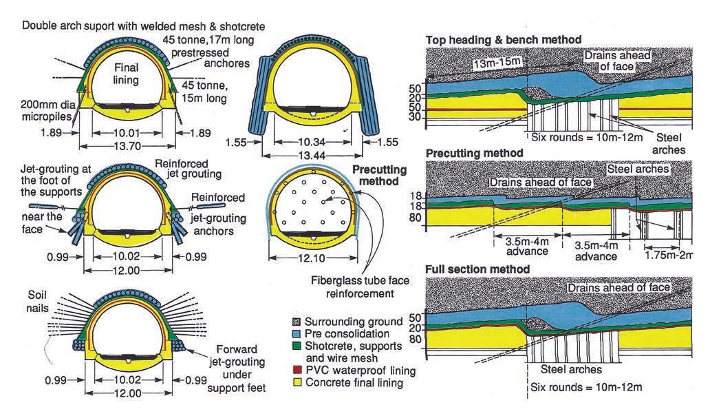
Fig 5. Ground conditions in most of the tunnels on the 44km-long project proved much worse than anticipated and the method of tunnel excavation had to be changed dramatically to suit the prevailing ground conditions
The waterproof system is supplied and installed on a sub-contract basis by Isomat. The final lining is cast using 13.5m-long forms supplied by CIFA. There are also two types of artificial tunnels used on the project. A cut-and-cover rectangular section built between slurry walls and an arch cast on tunnel formwork and then back-filled.
Another complex part of the project is an interconnection between the old and new lines. The interconnection spurs are actually executed in tunnel with one of the 65m2 single-track tunnels passing directly beneath the new double-track tunnel above with only about 20-50cm between (Fig 4). Each of these tunnels is about 1.8km long and were excavated using the pre-cutting system.
At the time of the site visit, the contract was into its fourth year and some 80% of tunnel excavation was finished. Despite all the problems, Fe.S.P.I. had persevered with the work and all tunnel excavation was expected to be completed by the beginning of 1991. The 44km missing link and the interconnection is scheduled to come into operation early in 1991 but at about 20% more than the original 1984 contract price. The total 1983 bid price of 714 billion lire has risen to 850 billion lire with most of this due to a 100 billion lire, or 35%, increase in tunnel costs from the bid value of 305 billion lire to 415 billion lire. "Had the actual behaviour of the ground on excavation been apparent before we started, we might have approached the task in a different way", said the Fe.S.P.I. spokesmen. "The problem with current site investigation practices and laboratory tests is that they provide point information along the alignment but with tunnels, one should have volumetric information. More precisely, it is not possible to obtain information on the behaviour of joints between different layers nor on lenses which are completely missed during sampling.
"Nevertheless, our extensive investigations testified that using roadheaders was the most appropriate method of excavation. Even on the static Dutch cone penetration tests in the sands, resistance was soon obtained predicting that we would be dealing with very dense sands, but this turned out not to be the reality.
"Having now experienced the ground conditions, and speaking purely hypothetically, perhaps a double-track blade shield with a precast concrete lining on longer lengths of tunnel might have been more appropriate, such as the double-track, blade-shield was used for a section of the metro system in Hamburg, but to adopt such a method for the shorter tunnels of the given scheme would have been much more expensive than those we chose to adopt. The cost of the portals would have been very high as well."
When asked about the possible use of the multi-phased, side wall drift NATM approach as a possible alternative, Fe.S.P.I. engineers replied that the philosophy adopted was to excavate the large cross section in as few steps as possible since time was a major factor in completing the work. Also, there was little experience of NATM in Italy and it was considered better to deal with a method for which the time, advantages and drawbacks were absolutely clear. In addition, excavation of the side wall drifts would require particular equipment small enough to drive the 35m² sections. It was therefore easier and cheaper to use machines capable of excavating the 65m² top headings and the 100m² full sections.
Despite the problems, the first 32km and the interconnection of the last 44km-long section on the Rome-Florence Direttissima is to be handed over in May 1990, five months ahead of schedule and in time to be used during the World Cup football games in June. Pendolino trains will transfer to the old line via the interconnection until the last 20km comes into service in early 1991. n
CASE STUDY: Italy has embraced an ambitious high speed rail expansion programme with apparent confidence and much public promotion. Although funding remains a concern in the time of EU single currency convergence, start of construction on the Rome-Naples line and award of construction contracts for the Florence-Bologna line are indicators of a positive commitment.
With reported estimates of 5,500 billion lira (about US$3.5 billion) for the Rome-Naples line alone, Italy's proposed investment in high speed rail links is one of the most ambitious public infrastructure programmes in Europe. Construction of the first high speed rail lines, capable of sustaining passenger train speeds of up to 300km/hr and with the capacity to carry freight traffic, began in Italy in the 1970s with doubling of the Florence to Rome line. Today, Italy has plans for seven new routes running across the country and linking with neighbouring European networks (Table 1).
In efforts to manage this exceptional capital investment and operate the high speed services, the State Railway Corporation (Ferrovia del Stato - FS) established a new division known as Trena Alta Velocita, or TAV. TAV set up a subsidiary known as ltalFerr-SIS to manage construction of the TAV projects.
A measure of TAV's success is that general contractors comprising JVs of Italy's largest and most experienced construction companies have been appointed to manage design, construction and implementation of all seven proposed lines on a turnkey basis and that two of the lines (Rome-Naples and Florence- Bologna) are under construction.
In adopting the current high speed rail plan, the Italian Government has declared that 40% of the necessary funding will be contributed by the State through FS, with the remainder raised as private venture capital. Loans and grants from the EU are also expected, however, success of the programme will depend as much on securing the funding as it will on managing the scale of the works.
Given the mountainous topography, the moderate gradients needed to sustain high train speeds, and pressures to protect the environment, each of the proposed lines includes a significant length of tunnelling (Table 1). On the 220km long Rome-Naples line, there will be 23 tunnels totalling 30km. On the Florence-Bologna line the proportion is more significant, with 71km of the 90km long line underground. A further 12km of tunnelling will provide access adits.
The existing Florence-Bologna line was built in the 1930s and comprises two lines, much of which runs through single-tube, double-track rail tunnels. The new line will double the existing capacity and ease congestion for both passenger and freight trains which travel the line, sometimes at only five-minute intervals. The new line
will not shorten the line length significantly, but it will constitute an express link with no intermediate stations and is designed for train speeds of up to 300km/hr.
Turnkey contractor for the Florence-Bologna line is the Fiat-led consortium CAVET, comprising lmpregilo; FiatEngineering; lmpresa Fortunato Federici; Cooperativa Muratori Cementisti; ltinera; and Consorzio Ravennate Cooperative Produzione Lavoro. Principal tunnelling subconsultant is Rocksoil of Milan.
Tunnelling is anticipated to be difficult, traversing clays, marls, argillaceous and stratified rock, with squeezing or swelling ground and major fractures through which water ingress is expected to be high.
In preparing its overall tunnelling design, Rocksoil is expecting application of the widest possible range of large cross-section tunnelling techniques, from drill+blast with the minimum of primary rock support, to central pilot tunnel excavation from within which the surrounding ground will be treated before excavation. Precutting is another technique to be used, with Trevi the successful sub-contractor.
Construction of the line is scheduled to take about seven years, with as many as 42 faces advancing concurrentlyat peak of construction. Work on the line started in 1996 with the excavation of two of the many access adits required.
IRICAV, a consortium of lritecna; Ansaldo; Condotte; ltalstrada; Astaldi; lcla Construzioni; Vianini-Lavori; and Consorzio Cooperative Construzioni, is the general turnkey contractor for the Rome-Naples line. The partners are responsible for eight individual sections of construction. Pegaso, the JV between Astaldi; Ansaldo;
Table 1. Scope of work and contractors chosen for Italy’s seven new dedicated high speed rail links
and Consorzio Cooperative Construzione, is in charge of Sections 2, 3, and 4 south of Rome, which includes the Colli Albani Tunnel (see editorial side bar). ltalstrada is managing Section 5; Vianini-Lavori has Section 6; lcla Section 7; and Condotte Section 8. Line links into the cities of Rome and Naples are yet to be finalised, with planning permission for new rail routes being sought and decisions about at grade or tunnelled alignments under the cities to build these links still to be made.
General contractors for the other proposed high speed lines have been appointed but the construction schedules await secured sources of funding. n
Using various methods of pre-support to pass through unstable ground is not new, but a novel concept developed by the Italians is well tagged as the Pretunnelling method.
The Premill technique of pre-supporting a tunnel advance with a slot cut with a chainsaw-type machine filled with concrete to provide pre-support before excavating the next round. The Italians, however, have taken a quantum leap forward with the Pretunnel technique. The slot cut by the Pretunnelling machine can be 400mm, 800mm, or 1100mm wide and up to 12m deep. It can cut in a leapfrog pattern or in a continuous arc and filled concurrently with cutting. Excavation of the core can start 24hr after completion of the Pretunnel cycle.
Designed as the latest step in the pre-support concept, the technique has been developed by sister companies Soilmec as manufacturer and Trevi as operating contractor, with geotechnical and tunnel design expertise provided by Geodata of Turin. The second model of a factory prototype is being tested on a short, 75m long tunnel on the Rome-Naples high speed railway line for possible application on future projects where squeezing ground and other particular geotechnical concerns require heavy pre-support.
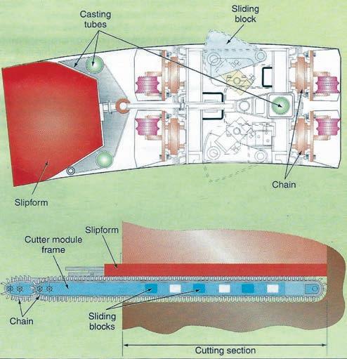
The massive machine weighs 300 tonnes and is driven by two 330kW diesel motors. The huge blade, or cutting module, weighs about 60 tonnes and is supported by two rotating drums, one either end of the machine. These are driven by two separate couples of drive motors, each of 280kW maximum power, to pull the module through the ground to cut the continuous annular conical slot of the Pretunnel canopy. The Castello Pretunnel machine can cut an internal radius of 5.8m-7.1m.
For continuous cutting and simultaneous slot filling, a slipform is attached to the blade to contain the concrete and protect the blade. Concrete is pumped through tremie pipes with ports at different positions along the full length of the slipform. At Castello, the cutting module is fitted with two 400mm wide chains to cut an 800mm wide x 10mdeep continuous slot. The chains are fitted with both picks and small 150mm disc cutters to cut through harder material. The machine is moved into the tunnel and lifted on to four stabilisers which centre the machine in the face. The blade is sumped into the face on a 60° angle to the
At 6.6km long, Colli Albani is the longest tunnel on the Rome-Naples high speed link. As well as the two portal headings, two intermediate adits open up four more points of attack to provide for an accumulated average advance of 50m of fully lined, 130m² single-tube, double track tunnel/month.
Colli Albani traverses largely volcanic material below a 15-70m overburden. Ground comprises hard basalt, tuffs, ash sediments and pyroclastic rocks, often presenting mixed face conditions. Pegaso, a JV of Astaldi, Ansaldo, Consorizio Cooperative Constuzione, is principal contractor. Sub-contracted tunnel excavation is to Demolscavi, which is responsible for excavation, muck disposal and primary lining. Principal design consultant is Rocksoil of Milan.
The rock along Colli Albani is mostly stable with the alignment running well above the watertable. Demolscavi is using excavator-mounted hydraulic breakers to work the full 130m² face where possible. Drill+blast is used for the hard basalt at 160-180N/ mm² in compressive strength. Steel ribs provide the primary support foundation, complemented by layers of wet mix shotcrete. Advance rates of 9m/day working on a three 8h shifts/day, 5 days/wk schedule have been achieved.
In weaker, less cohesive material, typically at the portals and below shallow cover, the ground is pre-supported with horizontal jet piling and 17.5m long glass fibre face nails. Horizontal jet piling is installed to provide a support canopy of 5.5m on an overlap of 3m.
Pegaso is installing the final lining concurrently. CIFA supplied gantry-mounted formwork and mobile high capacity wet-mix shotcreting units. The robust tunnel forms are 12m long and run on rails set on sidewalls cast as part of the tunnel’s in-situ concrete invert.
Between tunnel advance and final arch lining the now standard waterproofing membrane is installed. With work progressing from six points Pegaso reports a cumulative rate of 50m/month of completed tunnel. Excavation began in October 1994 on the two 80m² x 210m x 250m long access adits, due to become emergency exits. Excavation is set to end in 1998. By mid-Feb 1997, 80% of the tunnel had been excavated, with 10% completed to final lining.
A 12m long set of CIFA formwork is casting the final insitu concrete lining of the Colli Albeni rail tunnel
tunnel’s longitudinal axis. After the Pretunnel slot is cut and filled, an 8m round of the tunnel is excavated leaving a 2m overlap under the 10m long Pretunnel support arch.
It was initially intended that excavated muck would be withdrawn from the slot by a vacuum system. However, because water was being injected into the slot to suppress dust, thick mud was created which defeated the suction system. A slurry mucking system was considered too uneconomical because too much water was required to remove too little muck. Instead, the cut material at the Castello Tunnel is being removed by the rotation of the blade and allowed to fall to the tunnel invert into two small mini-excavators.
To control and support the 60 tonne blade while it is cutting, sets of lateral blocks or grippers on the module brace it within the slot. These blocks steer the cutting module and control injection of the concrete to ensure uniform fill and an even cut. When cutting, the blade rotates at approximately 50 rev/min and a maximum thrust of 50 tonnes is exerted by four hydraulic cylinders to sump the module.
Theoretically, it takes about 24hr to cut and fill a 10m slot for the Castello Tunnel, which is 13.5m wide x 13.2m high with a cross section of 120m2 and a span of 10m. The Pretunnel machine cuts a 270° arc to provide the 800mm thick in-situ concrete pre-support. Excavation must then be delayed for 24hr while the concrete acquires a strength of 20MPa before the next 8m round. At the Castello Tunnel, the theoretical rate of advance through low cohesive shaley and silty tuff is one 8m round/wk per 24h/day x 5 days/week.
During the site visit, the machine had cut and advanced the first two of the nine rounds needed to complete the 75m long tunnel, but had been halted awaiting a new set of bolts for the blade’s cutting chain. The load on the chain is very high, with the torque rising to 5 tonne-metres in harder material. The chain is designed and supplied by Caterpillar.
The machine is operated by a crew of two as required by Italian safety rules. One moves it into position and the other drives the blade and controls concrete injection. Control of cutting and filling is governed by the monitoring of various parameters, including thrust, inclination and injection pressure. The machine’s weight of approximately 300 tonnes was considered essential to counteract the thrust driving the blade and could even be increased. More weight still would provide greater stability and better balance of the heavy blade. More weight, however, would focus attention on the tunnel invert. If the load bearing capacity of the ground is low, an invert of cast concrete or 400/500mm of steel fibre reinforced shotcrete would be required to support the huge machine.
After placement of a waterproof membrane, the Castello Tunnel will be finished with a final unreinforced in-situ concrete lining. n
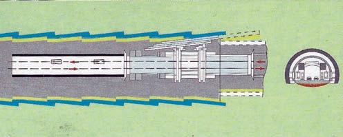
2. A gantry-type configuration of the machine will allow the use of Pretunnel technique to enlarge existing road tunnels and excavate the core during limited closure
CASE STUDY: In 1962 Italian tunnellers using hand mining techniques to excavate the Galleria Aurelia railway tunnel through wet running ground conditions under the streets of Rome were forced to abandon their gallant efforts. It remained in this unfinished state for almost 20 years. In that time, technology advanced to the point where difficult geology is no longer the tunnelling obstacle it used to be. In the early 1990s a highly specialised mechanical method and the world’s largest Hydroshield at the time completed the 10.64m diameter tunnel drives started originally in 1948.
Like most major European cities whose origins stretch back centuries, Rome has had its problems coping with the age of the train to say nothing of the motor car. The opportunity to expand existing surface train links through the centre of the city was never presented. The compromise is to complete a circular rail line around the perimeter of the city connecting main national railway lines, regional lines and the city’s existing and future metro system.
To accomplish this in Rome, it was decided to connect the Genoa-Pisa line to the main northern line from MilanFlorence to close the northwest section and to connect this to the southern section to close the ring. In 1935 studies began for a new 29km long twin track line to connect Maccarese Station on the western line to Rima Smistamento Station with some 10.8km running in 55m² horseshoe-shaped tunnels (Fig 1). The longest tunnel, Galleria Cassia, is 4.4km long with the second in length, Galleria Aurelia, 3.3km long.
The Galleria Cassia under the northern section of the city being driven by Italian contractor ICOR1, successfully holed through in April 1984 but it was to Galleria Aurelia that a visit was carried out in early 1984.
• Client: Ferrovie dello Stato (State Railway), Direzione Generale, Unita 3 Speciale
• Contractor: Ferrofir Consortium comprising the contractors Astaldi, Dipenta, Lodigiani and S G I Sogene Lavori
• Tunnelling machine manufacturer: Bade & Theelen GmbH of Ronnenberg, West Germany
• Manufacturing consultant: Wayss & Freytag, Germany
Construction works on the line started in 1948 with traditional hand mining excavation techniques being used to drive the tunnels through very soft water bearing ground. Timber supported 2m x 2m pilot tunnels paved the way for subsequent benching to the full 55m² profile which was supported with steel arches and lined with 1m thick concrete brick work. The pilot tunnels were always between 20m-50m in advance of the benching works.
These commendable and valiant efforts continued for some 14 years until in 1962, when 27km of the line was almost complete, work had to stop. Ground conditions were considered too dangerous to continue hand mining. The main defeating factor was the ingress of incredible amounts of ground water and sand. Acting under a 10m

head of pressure, this dewatering of the ground was causing serious surface subsidence of up to 1m in places. When work stopped, of the 2,950m required, some 1,500m from the west portal and 850m from the east portal had been successfully excavated. The project was to remain in this unfinished state for the next 20 years, with available resources spent on other more pressing railway projects and the Rome Metro system. Then in 1974, a plan to link the new Fiumicino Airport to the Roma Termini and the Metro revived the idea of a complete orbital rail system. Also, the anticipated 1976 inauguration of the new high speed railway line between Rome and Florence, known as the Direttissima, added pressure for a western rail link around Rome (Fig 1).
Initial action on the idea called for tenders to resume and complete the two tunnels started in 1948 with more tunnelling required at the Aurelia site to form a west/ south link to Roma Trastevere terminal (Fig 1). Here the successful contractor would have to finish the remaining 900m of the original tunnel, drive the new 2,000m section around to Roma St Pietro Station and carry out extensive rehabilitation works on the completed sections of the old tunnel. Over years of neglect, these had, deteriorated badly. Constant water ingress and water pressure acting on the tunnel had caused the invert to heave in places and the walls and crown to warp and crack to a dangerous extent. In some places the tunnel profile was deformed by as much as 1m.
In 1975, the contract for the entire Aurelia works was awarded to a joint venture of four Italian contractors; Astaldi, Dipenta, Lodigiani and SGI Sogene Lavori. These companies came together for the first time in 1970 to construct 42km on the Rome-Florence Direttissima express railway which included excavation of the 7.5km long X 92m² horseshoe shaped Castiglione Tunnel and it is from this job that they took their joint venture title Ferrofir (FERrovia ROma FIRenze, Railway Rome Florence).
With the imminent completion of that tunnel, Ferrofir was looking for another project to use its Robbins soft ground tunnelling shield which had performed very well in the over consolidated clays and middle conglomerates encountered in the drive.[1] Winning the Aurelia contract appeared ideal since the geology of the first 1,000m was similar. But on closer examination the idea had to be rejected.
The geology of the Aurelia site is composed mostly of sedimentary alluvial ground in layers of monogranular
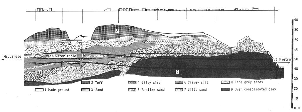
sand to 0.5mm, non-cohesive washed sands and gravel, silty layers and over consolidated Pliocene clays all under a volcanic tuff cover. Overburden varies from 25m to 35m, and the water table has a head of up to 25m in places. In addition, there are artesian lenses in the sandy layers in the middle of the tunnel line and another just below, with water pressure varying from 6n to 11m. There are also many water springs which work their way eventually into the Tiber Valley.
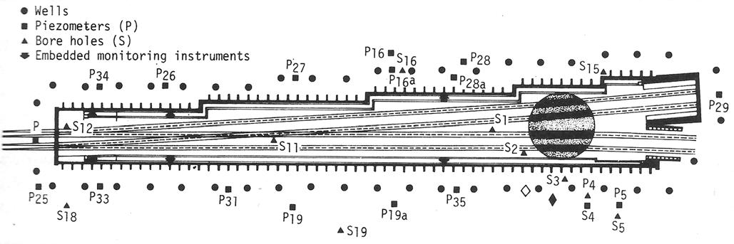
Gathering enough detailed information to compile the accurate and comprehensive stratigraphical section of the 2,500m tunnel line from St Pietro Station to the front of the existing old tunnel (Fig 2), required the drilling of many exploratory boreholes. The client drilled one hole every 200m and Ferrofir made a further site investigation by boring and performing geotechnical tests along the line. The tests confirmed too, that the tunnel route runs across an eroded valley in the geology. Realising this, it is no wonder the traditional techniques used on the initial tunnelling attempts had to be abandoned.
With this type of geology under much of the ancient city, fear of surface subsidence has been a constant worry and was a serious problem during construction of the Metro in the 1970s. Therefore, on resumption of this tunnelling contract, the main objective was to minimise ground settlement. Fortunately, the visible surface subsidence over the already excavated section of the original tunnel prevented the construction of buildings on the unfinished section. But the new tunnel section from St Pietro station, passes under a built-up and old section of the city within a few hundred metres of St Peter’s Basilica and the Vatican City. In fact, special permission had to be granted by the Vatican Administration for Ferrofir to provide water from an aqueduct suppling the Vatican fountains to cater for its water needs on site. Subsidence damage here would prove costly in both time wasted and money spent on compensation. The client therefore demanded guarantees that no damage due to settlement would occur. Choosing a machine to comply with these strict specifications would be critical with the most important consideration being the prevention of a face collapse.
Ferrofir first considered modifying its Robbins shield to the require dimensions and power, and using it to excavate the first 1,000m of clay and applying compressed air for the second section, or at least the part of it which is under the water table. In addition, a pile diaphragm wall was to be installed along an important road to avoid ground
decompression during excavation and limit subsidence of buildings. Considering all the difficulties this proposal involved, Ferrofir widened its research of possible alternatives and it was through the pages of Tunnels & Tunnelling magazine that such an alternative was found: a shield with a continuous face support provided by bentonite slurry.
There were three possible options. The machine developed by Priestley of the UK which was the first slurry machine invented; the design of the German company Wayss & Freytag; and the third developed by Japanese manufacturers.
After negotiations with the British and German firms and after seeing the Hydroshield in action on the Antwerp Metro project in Belgium, (the Hydroshield was the choice.[2]
Following months of close cooperation with Wayss & Freytag’s tunnelling department, specifications for a new 10.64m o.d. Hydroshield were prepared and Bade & Theelen of West Germany was commissioned to manufacture the biggest Hydroshield ever.
It is easy to understand how big a step had to be taken by all involved in the venture - designers for the increased diameter, contractor for the increased cost as the amount of the tender had to remain fixed, and for the client which had to support the use of a machine in its very first application. In December 1978 the green light was given and construction began.
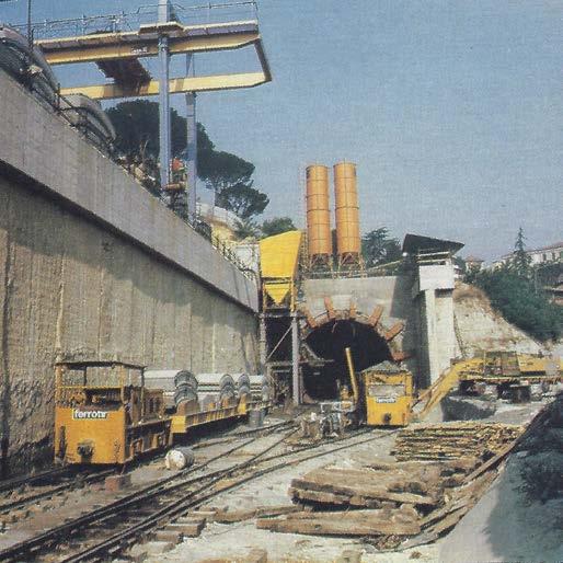
Ferrofir proposed to start tunnelling from the St Pietro Station and carry out concurrent cut-and-cover construction of the Camerone junction chamber. After driving the first 2,000m on its 750m radius the machine
would be lifted through the 200m long chamber and lowered again to drive the 300m between Camerone and the end of the old tunnel. Here the shield of the machine would be abandoned and the components assembled in a new shield erected at the east end of the Camerone ready for the last 400m drive to the old west portal drive (Fig 1 inset).
While awaiting delivery of the machine, extensive site preparation was carried out to provide a suitable assembly area in very tight access conditions beside existing operating rail tracks at St Pietro (the east portal) and construction of the Camerone junction box began.
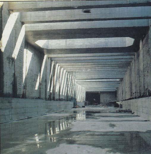
The Camerone box is 200m long x 24m deep x 18m wide at the narrow end, increasing to 35m wide at the flared end. Its exact location and depth was determined by the position of the old partly excavated tunnel line and by the topography of the area (Fig 2). It was decided to construct it where the overburden is the shallowest and where tunnelling would be more difficult than cut-andcover work. A complete slurry wall was first constructed around the entire perimeter. Some 144 T section holes 3m across x 2.5m wide x 29m deep were excavated and supported with bentonite for the T steel reinforcement to be inserted and the bentonite replaced with concrete.
Before excavation could start, 60 x 45m deep dewatering wells were installed around the perimeter to depress the water table form 6 to 25m from the surface (Fig 3). This was necessary until support structures were completed. An incredible 4 and 6 litre/s of water was continuously drawn from each well. After excavating the first 8m, poured concrete cross beams were installed to brace and strengthen the walls against the increasing pressure with depth. Excavation continued to within 4m of the lower edge of the diaphragm walls. An in-situ concrete floor was then cast and the concrete roof erected. Recordings from strain gauges and pressure cells embedded in the walls to monitor their condition were the subject of a paper presented at the XV National Geotechnic Meeting at Spoleto in May 1983.[3]
Construction of the Camerone started in July 1979 and was completed in September 1981. In April 1980 the components of the Hydroshield arrived for assembly which took about six months. In the meantime, a 24m long artificial concrete tunnel was constructed as a launching pad for the machine. October 1980 marked the start of the drive.
As can be seen from the stratigraphical section (Fig 2), the first 1,000m of the tunnel is through homogeneous over consolidated clay without great problems about the stability of the face. The shield was used in this zone as a dry, open faced machine. Two gathering arms and a chain conveyor loaded a six wagon train with a 90m 3 capacity which removed the muck from the face. Once near the end of this zone, the machine would be changed with minor modifications to the Hydroshield slurry mode to work through the softer water-bearing layers.
Work in this ground was quite slow since the site area at the portal was very narrow requiring the use of a fleet of dump trucks to muck out for almost 150m before all the service rails and switches could be built in the tunnel and at the portal. Also, the clay was falling away from sliding surfaces in large blocks making mucking out difficult. Excavation of the first 850m section took from October 1980 to September 1981 with a best month advance of 125m working a 3 shift/24h day, 5 days/week.
From September 1981 to February 1982, conversion of the machine from the dry to the wet mode was accomplished but just at that time the client’s administration passed from the Ministry of Public Works to the Ministry of Transport and work on the project had to be suspended until May 1982.
When work resumed, progress was once again very slow because of the necessary learning curve for the new technique. Driving through the last 300m of clay was also quite difficult since, once mixed with the clay the bentonite became very sticky causing frequent plugging of the suction pipe requiring manual flushing. During this
stage, many technical improvements were investigated and applied to achieve a more satisfactory performance from the machine. The most critical period occurred when several different layers of material were present in the face including calcareous sandstone, accompanied with high ground water pressures. In cases like this the balancing pressure in the shield’s air cushion has to be very accurate. The maximum pressure applied in this cushion to date was 2.2 bar. But this also carries the danger of breaking the 33m long circumferential seal around the tail skin and forcing the bentonite slurry mix back into the tunnel.
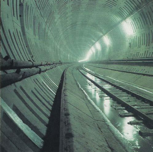
However, to talk about the effectiveness of the shield, one must also pay attention to the kind of lining used. Because the tunnel is being driven below the water table the precast bolted concrete segments erected within the tail shield must be made watertight immediately. The eight segments + key unit + three invert elements that make up each 1.25m wide ring, cast at a fabricating works 18km from the tunnel site, were measured to 0.1mm tolerances to ensure the specified mechanical precision required. Each accepted element was then fitted with a complete neoprene rubber gasket adding up to 77 linear metres of sealing/ring and transported to site for building into the tunnel.
When the machine reached the full extent of its 1.75m stroke, not all the 32 x 200 tonne x 400 bar capacity thrust rams are retracted at once since the 1,000 tonne counter pressure for each bar of forward pressure acting on the face would force the machine backwards. Only three pairs of jacks are retracted together to allow the mechanical placement of the 50cm thick x 4m long x 1.25m wide x 5.25 tonne maximum sized elements starting with the invert sections. The segments, transported to the face by rail, are lifted up to an overhead conveyer at the lead end of which are two, mechanical erector arms which place each segment in turn (Fig 4). Once bolted together both segment to segment and ring to ring, the jacks are engaged again on the lining’s continuous pattern of greatest strength. As soon as the machine begins to push forward on its next stroke, pressure grouting must begin
to prevent settlement on the ground into the overbreak left by the shield as well as avoid any leakage of the face bentonite through a burst seal. This grout is injected at 2 to 4 bar pressure to slightly over-compensate the pressure of the bentonite on the face. Approximately 4.5m³ of grout mixed at the portal batching plant is injected behind each 1.25m ring.
Besides these stringent waterproofing requirements, 2cm tapered rings were required to allow for the 700m minimum radius curve of the tunnel line. This also provided a means of correcting the position of the shield relative to the lining. This immediate bolted lining is also the finished tunnel. A secondary in-situ concrete lining will not be necessary.
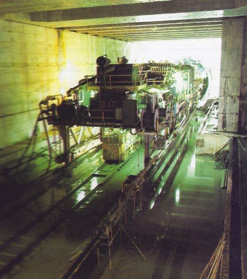
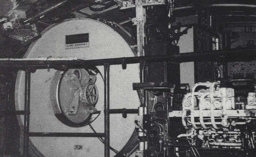
The operation of the giant Hydroshield is an exercise in perfect timing, careful monitoring, patience and trust. Since the face is completely obscured by the steel bulkhead, a watchful eye must be kept at all times on an impressive array of dials, LED digital displays and gauges on the operator’s console which indicate exactly how each component of the machine is behaving (Fig 4). The basic design of the Hydroshield is described in the paper presented by Ing Gianfranco Prati to the XIV National Meeting of Geotechnics.[2]
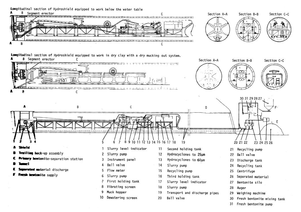
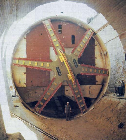
The key of the technique is the mixing of bentonite with the soft materials in the face and the pumping out of the resulting slurry with subsequent recycling of purified bentonite. In this case a Sardinian bentonite is delivered in a dry powder form and stored on the St Pietro portal site in silos. This is mixed as required and stored in 2 x 60m3 tanks. At the beginning fresh bentonite is pumped to a 150m3 storage tank on the machine and from here into the excavation chamber as required. Here it forms a thin cake over the exposed ground, thus providing a barrier which is held in place by a hydrostatic pressure increased with an air pressure cushion to counter ground water pressure, thus stabilising the face. As the large spoke-type cutterhead rotates, material falls to the invert where it breaks down and mixes with the bentonite to form a slurry. This is pumped out to the first separation
stage located 60m away on the trailing backup assembly where a vibrating screen filters particles of more than 2mm. The slurry overflow is pumped at a rate of 800m/ hr to two 50cm diameter cyclones that filter particles of up to 60μ. Overflow from here is pumped through 32 x 15cm diameter cyclones which filter particles up to 25μ. The purified bentonite is then pumped back to a 150m3 holding tank and the separated material is dumped into a 4m3 sludge hopper. A mucking out train of 6 x 15m3 side tipping cars, hauled by a 165hp Plymouth diesel loco transports this muck to a 550m3 trench adjacent to the tracks at the portal. From here it is loaded by a backhoe into dump trucks for disposal.
A third finer purifying cycle takes place outside the tunnel. From the holding tank on the machine, the bentonite is pumped out at a rate of 150m3/hr into a 350m3 tank on the surface. From here it passes through a centrifuge and is purified to 10-15μ and returned to one of three 42m3 holding tanks for later pumping back to the machine’s reservoir which is topped up with fresh bentonite as required.
In normal conditions, about 70% of excavated material is removed in the muck car and 20% separated in the cyclone and centrifuge purifying procedure. The remaining 10% of fine material increases the density of the bentonite which must not exceed l.40kg/litre. Therefore, it is necessary to draw off about 200m3/day using a tank truck and replace it with fresh bentonite.
The excavation cycle from a transport point of view starts with a train comprising six muck cars, two flat cars carrying the segments for a complete ring and a 5m3 mixer car of grout, pulled to the face. Here it runs up onto the double track 70m long rubber tyred sliding floor of the machine’s back-up trailer. First the mixer is shunted up alongside the 5m/hr permanently fixed Schwing grout pump which feeds two independent injection hoses. The flat cars are behind it, under the crane which lifts each segment onto
the overhead conveyor assembly. The empty cars are uncoupled and shunted onto the adjacent set of tracks ready for filling from the overhead muck holding hopper. A continuous rotating programme of three such trains is maintained with the out bound train being passed on California switches installed every 800m.
The 70m long trailing back-up system consists of seven independent but linked sections instead of a rigid assembly in order to take in the 700m radius curve of the tunnel. All the essential equipment is located on the upper level of the trailer. The operator’s station and the compression chamber that allows man access into the pressurised face chamber are also located on the upper level. Access to the face is required about 3-4 times a week for the removal of clay blocks or boulders and to check the cutting teeth, replacing any that are worn out. Cutter wear depends greatly on the local ground conditions but in silty sand without conglomerates, the entire set of 84 cutting teeth has been replaced every 400m or 4 months.
Working in the wet Hydroshield mode a maximum seven rings per three 8hr shifts/day are being erected, equalling about 9m advance/day. Rates of advance cannot be easily increased since they are influenced more by the design capability of the cutterhead. Due to the length of this tunnel production of five rings/day is the accepted average. The pipe diameters of the bentonite system limit the rates since they can handle only this amount of muck/day. Larger diameter pipes would only increase the chances of blockages occurring in the system. The grouting cycle limits the advance rates since it is not safe to excavate faster than the capacity to inject grout behind the lining. Segment ring build, due to the precision required, is another limiting factor. An increase in production, even if possible from a technical point of view, could not be justified economically since operating costs would increase rapidly. Only a longer tunnelling
project would justify this cost for the contractor. Advance therefore is the optimum achievable after synchronising all the various operations involved.
With constant rates achieved every 5 day week, the remaining 1,150m Hydroshield drive from St Pietro, started in May 1982 and broke into the Camerone in September 1983. After transporting the machine through the junction it was lowered into the launch area for the second short drive to the old tunnel.
During the site visit, the machine was within 20m of meeting the face of the old 50m long pilot tunnel and production had stopped while plans of how to cope with this were finalised. It was decided that men would have to work within the compressed air excavation chamber to manually dismantling the old timber and brick lining a metre at a time before the machine could advance. However the air pressure required to stabilise the face in this soft water bearing ground exceeds the 1 bar maximum limit for man entry. The solution is to sink a number of dewatering wells to lower the acting water pressure allowing a low air pressure in the face and a longer working period for the compressed air crew.
Later reports from Rome explained that the pilot tunnel which is some 20m below the surface has been removed by open trench work. The machine has now to drive the full profile and break through into the old tunnel.
In preparation for the third 400m drive from the Camerone to junction with the old tunnel a new shield skin to replace the sacrificial first one arrived on site in February 1984. After transferring vital equipment into this new shield, the last drive was expected to start in January 1985.
New line out of the old
Concurrent with all this tunnelling work, another crew was rehabilitating the old tunnel sections. To start, sets of steel arches, held in place by short hydraulic jacks, had to be erected to support the dangerously warped and cracked lining. Because the profile was so distorted, a new profile had to be established. After casting a level walkway down each side of the tunnel, a telescopic shutter of 2 × 12m long crown only sections, was introduced, behind which a new in-situ lining to a uniform profile could be cast. New walls were then excavated in 3m to 5m long sections and finally the invert was lowered to establish a new tunnel on a slightly lower line than the old.
The concrete for this part of the project is transported in 9m³ mixer trucks from the batching plant some 16km away. Between 60m³ and 110m³ of concrete is place behind each of the 4X6m long telescopic elements. A single boom Worthington pump placed the concrete via the one concreting window in the soffit of each element. Twelve metres of new concrete lining was completed in each 24hr x 5-day working week.
After the guided tour of this complicated project, it is clear that Ferrofir is continuing a legacy of fine tunnelling left by the hand mining crews of 20 years ago, but with the help of the most sophisticated soft ground tunnelling machinery currently available. All along the tunnel route which follows a major surface roadway, highly sensitive electronic equipment is being used to measure both transverse and longitudinal sections to detect settlement and surface subsidence in 1/100mm. The maximum
surface settlement recorded so far is 7mm at a section where the machine was 2½ times its own diameter below the surface. Working under this relatively shallow cover has created its own set of problems.
At times, the foundations of buildings were only 8m above the crown of the tunnel and others were only 1.5m away from the sides of the drive. At one point, the foundation piles of a bridge carrying the road over a major highway on a lower level were too deep and close to allow passage of the machine underneath. Without disrupting the traffic on either road, a new bridge had to be constructed. Even then there was only 40cm to spare each side as the machine passed through only 3m from the lower road surface.
This is a project that will be a case study, along with the construction of the Antwerp and Berlin Metros, (to prove the value of using the Hydroshield technique to drive tunnels through very soft water-bearing ground where minimum surface settlement measured in 0.01mm is absolutely necessary. It was reported that to gain the experience to cut future costs and recoup the capital investment involved, a contractor would have to use the machine on a project of more than 5km. But with the technique now proven, projects shelved in the past because the risks of settlement were too great can be revived and executed. This machine need never stand still. n
1. Ing Alberto Tarsitani, Ferrofir Site Manager. Report on application of a large excavator shield tunnelling systeme and precast concrete segment final lining for the Castiglione Tunnel, Italy. 1974 RETC proceedings, San Francisco, Vol 2, Chapter 106, p1631-1650.
2. Ing Gianfranco Prati, Ferrofir Technical Director. Hydroshield system for Aurelia Tunnel construction. 1980 proceedings of XIV National Meeting of Geotechnics, Florence.
3. Ing Valter Capata. SGS Geotechnical consultant and Ing Angelo Gicolani, Ferrofir design department. Behaviour of supporting structures during excavation of the Camerone switch on Rome railroad ring. 1983 proceedings of XV National Metting of Geotechnics, Spoleto, Italy
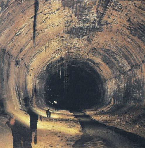
Galleria Aurelia lined with precast bolted concrete segments
1986 SITE VISIT REPORT
It is a small 220m-long tunnel needed to carry a 40cm i.d. waste water pipe 83m under a hill near Lake Como in northern Italy, instead of 7km around it. After convincing the client that driving a tunnel would not only save time but also be substantially cheaper, local contractor Caprile was engaged by main contractor Nessi & Maiocchi as tunnelling sub-contractor.
With little experience in tunnelling, family firm Caprile needed advice and support particularly from the supplier of the tunnelling equipment. In the hard limestone of the hill, use of drill + blast was almost a foregone conclusion. Handheld pneumatic tools were suggested but this would have been slow. Caprile chose instead to use a drilling jumbo in a larger cross-section and decided to rent a rig.
One manufacturer was only interested in selling a rig, another only had a 2-boom pneumatic rig available for rent which would demand high compressed air consumption and, as the tunnel need only be big enough to allow entry of the jumbo, 3m X 3m (8.03m²), two booms were not necessary. A small roadheader was also suggested but this would be about five times more expensive to rent.
Two suppliers offered to rent a 1-boom hydraulic jumbo and Caprile chose the Böhler rig supplied through Tisco of Milan. “The people at Tisco are well known to us, they have helped us in the past, and they put together a better package than the other supplier,” said Works Manager Emanuale Caprile.
The 50kW rubber-tyred electro/hydraulic Minbo 14R jumbo, is the first Böhler hydraulic rig used in Italy. Following a job in West Germany, it was reconditioned at the Böhler factory in Austria, fitted with a new HS432 hydraulic drifter and shipped to Italy.
In addition to the jumbo, Tisco included in the rent-andreturn package a spare drifter, 60m of electric cable, three boxes of spare parts and a laser. The deal also includes Böhler Robo drill steels and a Böhler technician on site for one month. Caprile has its own diesel-driven generator, air compressors, water pumps and ventilation equipment.
An old nearby quarry predicted competent limestone, however conditions proved more difficult. Under the hill, the limestone is heavily fractured and stratified with 2030cm thick vertical inclined layers running parallel to the tunnel face. The cracks and fissures are filled with clay and dry loose soil.
Caprile expected to complete three rounds/9h day drilling 30, 48mm-diameter X 3.7m-long, charge holes and two 76mm diameter cut holes into the 8.03m² face giving a progress rate of about 9m/day to complete the tunnel in two months. Progress is actually half that, with two rounds giving 3.5-4m/day.
To begin, the face was charged with about 3.2kg/m³ of Tutagex explosives from Italesplosive in 40mm-diameter X 400mm-long sticks, contour explosive in the periphery and wired with electrical detonators. In the stratified limestone, this caused excessive overbreak of about
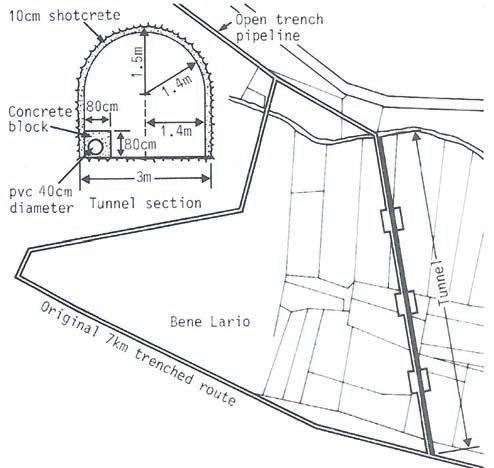
80cm-1m maximum which had to be filled with concrete behind steel walls and behind wire mesh and shotcrete in the crown. Charge holes have been shortened to 2.5m and the amount of explosive/hole has been reduced to try and control overbreak.
A greater problem is obstruction of the charge holes. As the bit passes through the stratified layers, dry debris from within the cracks falls into the hole which forms a collar around the bit as it is being withdrawn. As lead miner Claudio Caligari explained: “It takes about 3.5 min to drill each 2.5m-long hole and 6 min to withdraw the bit.” This debris also hinders loading of the charge holes particularly the small diameter contour charge holes. These are no longer used, which aggravates overbreak problems. Debris in the cut holes rendered them useless and these too have been eliminated. The central charge holes are drilled in a cone shape to serve the same purpose.
Tunnelling started in May 1986 and was expected to finish in September 1986, about one month later than the original two-month programme. This delay has been offset against the overbreak for which Caprile was not paid.
Tisco is also agent for Bade & Theelen of West Germany whose tunnelling machines, including the Hydroshield, have had remarkable success in Italy. n
CASE STUDY: Twelve months to finish a 1km long 22-28m² tunnel is not demanding in itself. But the fact that this has been achieved in difficult rock is a credit to the company and its crew and to the reliability of the machinery.
1989 SITE VISIT REPORT
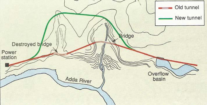
The 21MW Boffetto hydroelectric powerstation built in 1915 was one of many structural victims of the rainfall and snow melt deluge which devastated the Valtellina Valley in the Italian Alps in the Summer of 1987. The surface penstocks, the three turbines and the tailrace channel were severely damaged by the flood of water and debris, as was the headrace tunnel.
The Alps are a relatively young geological formation and tunnelling through them is not easy. When the headrace tunnel was built back in 1915, the engineers of the day, limited by the available technology and the urgent need for power, avoided recognised areas of difficult rock and took the shortest line to the station. This brings the tunnel to the surface at two points where the water is conveyed across two steep valleys in an open aqueducts (Fig 1). One was badly damaged by the raging torrents which swept down the valleys during the storms.
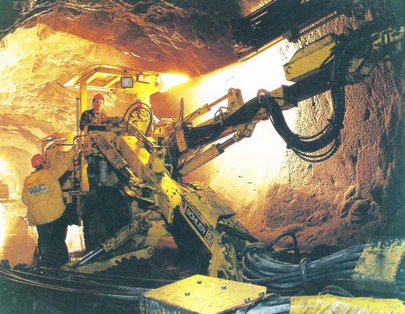
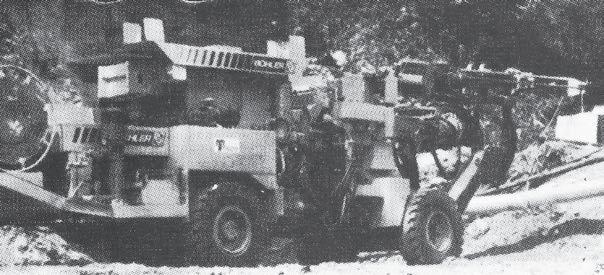
Böhler’s Minbo 26 twin-boom jumbo favoured for drilling speed and manoevrability in the small 28m² crosssection
A new 1km long tunnel is part of the reparation programme by the client, ENEL, the Italian national electricity company. Plans are to bypass and eliminate the old and potentially dangerous aqueducts. But the engineers and miners of 1915 knew what they were doing when they avoided tunnelling in this area, because even with today’s modern machinery and techniques, the going is tough.
The PAC/E Romagnoli JV won reparation contracts for the station in 1987 but the decision to build the bypass tunnel was taken late, putting it on the critical path. It had to be completed in just 12 months to coincide with completion of the other remedial contracts and enable the power station to be operational again as quickly as possible.
PAC is handling the tunnelling work, having won the £1.4m contract as the lowest of 20 or so competitors and work started in May 1988 by breaking out of the old concrete-lined tunnel from both ends.
Although fractured and weak in some areas, the rock on the whole is strong, with compressive strengths of up to 150MPa. Drill+blast was recommended by the client. Any alternative would be employed
at the contractor’s risk. A TBM was seriously considered, especially as a suitable TBM, being used in the vicinity by Murer, would become available in time. Murer would then be engaged as a sub-contractor to drive a TBM tunnel. However, the machine had a minimum radius capacity of 400m and the tunnel, as designed by the client, involved four curves of 100m radius. Also the length of tunnel was too short to make application of a TBM economical. PAC therefore decided to complete the work using drill+blast.
Being mainly involved in road projects and tunnel maintenance and repair work in the past, PAC had no tunnelling equipment and now needed two drilling jumbos. Initially it rented an Atlas Copco Boomer 137 but it proved to be a bit too big in the 28m2 tunnel. Smaller jumbos
Fig 1. The 4km-long run-off-the-river headrace tunnel included aqueducts over two valleys which are now being by-passed by a new 1km-long tunnel
with easier manoeuvrability were necessary. This was necessary particularly for the booms since the jumbos also drill the rockbolt holes and booms had to be swung into a radial position. The length of feed on the booms was also important in the 5.5m high tunnel for the same reason.
After looking at several machines, PAC rented two Böhler Minbo jumbos from Tisco, the Austrian company’s Italian agent. One is a used Minbo 26 machine and the other is a new Minbo 26 on which PAC took up its option to buy after three months. Both machines are 2-boom jumbos fitted with Böhler’s HS432S hydraulic drifters and have feed length of 3.8m. The Minbo 26 machine has the advantage over the smaller-bodied Boomer 137 in that a working basket can be mounted on one of the two booms. It is fitted when required for rock bolting, for example, and taken off when drilling.
The rock is typical of that found in this area. Some 80% of the drive is in mica schist, but for the other 20%, mainly at contact points behind the two valley regions where cover and distance from the rock face is reduced to 20m and 70m respectively, the rock is fractured, weathered and chemically disturbed, with a heavy water ingress potential of between 10 and 20 litre/sec.
Work in the good rock areas progressed well, with two or three blasts being achieved each day working three 8hr shifts/day. There are 60 x 48mm diameter charge holes in each face. In good rock, they are 3.8m long and take about 2.5min to drill. A drilling cycle in good rock takes about 2.5hr. The face is then charged with an average of 2kg/m3 explosive, 25mm diameter x 160mm long Proflix cartridges around the profile for smooth blasting and 40mm diameter x 400mm long Tutajex cartridges in the face holes, to produce a pull of about 3m. In good rock only rock bolts, mesh and shotcrete are required for immediate support but this is limited to about 30% of the tunnel. Steel arches on 1.2m maximum centres are also required for about 70% of the drive. Although smooth blasting techniques are being used, overbreak is difficult to control and has been as high as 1m.
Unfortunately, poor to very bad rock prevails on this job and there have been two roof falls in the drive from the
south and many small roof falls in the northern drive. The drive from the north is made more difficult in that it is a down-hill drive, the slight 0.08% gradient allowing water to flood the invert.
In poorer conditions, the charge holes are shortened to 0.5m long and steel arch spacing is reduced to 40cm. In such conditions, drilling is difficult and each hole can take up to 3.5 min to drill. In the worst conditions, PAC must resort to excavation by hydraulic rock breakers because, although the jumbos would perform better, the finished holes collapse and cannot be charged.
During a site visit, PAC was down to the last, most difficult 100m under the most southern valley where cover is 20m maximum, water ingress is at its highest and the rock is disturbed and weathered. PAC has since finished this difficult section using the jumbo over 70% of the distance and the hydraulic breaker for the remainder. To avoid the high possibility of a major roof fall, PAC used the spiling technique to provide advanced support of the ground prior to excavation.
The tunnel is now being finished with its in-situ concrete lining. The entire invert was cast first and the arch is being cast behind a 48m-long telescopic form supplied by Nassazzi. It comprises eight 6m long elements. With a striking period of 24h, concreting is expected to be completed by May 1989.
Successful completion of this job is a worthy initiation for PAC into the field of tunnel-excavation and strengthens its reputation as a contractor able to deal with small but technically difficult jobs. ENEL’s current policy is to buy up existing private power stations and upgrade them rather than build new schemes. As such, there is a substantial amount of specialist renovation work available. There are some up-grading projects requiring excavation work to bid which PAC is now equipped and well experienced to tender for. “This has been a difficult job for us,” said Ing Emilio Bianchi, PAC’s Job Site Manager, “and the work has not been easy. But we are pleased with the performance of the Böhler jumbos, particularly with the drilling speed and the manouevrability. We look forward to using the Minbo 26 on our next tunnelling job.” n
CASE STUDY: During the 1980s, a 50km potable water aqueduct was driven through the mountains near Naples in the largest project of its kind undertaken in Italy at the time. The project demanded the expertise of several Italian tunnelling companies, using various methods of excavation, from majority drill+blast and TBMs to artificial tunnels, through an extreme set of geological conditions, proving to be another test bed for tunnelling technology and the industry
1985 SITE VISIT REPORT
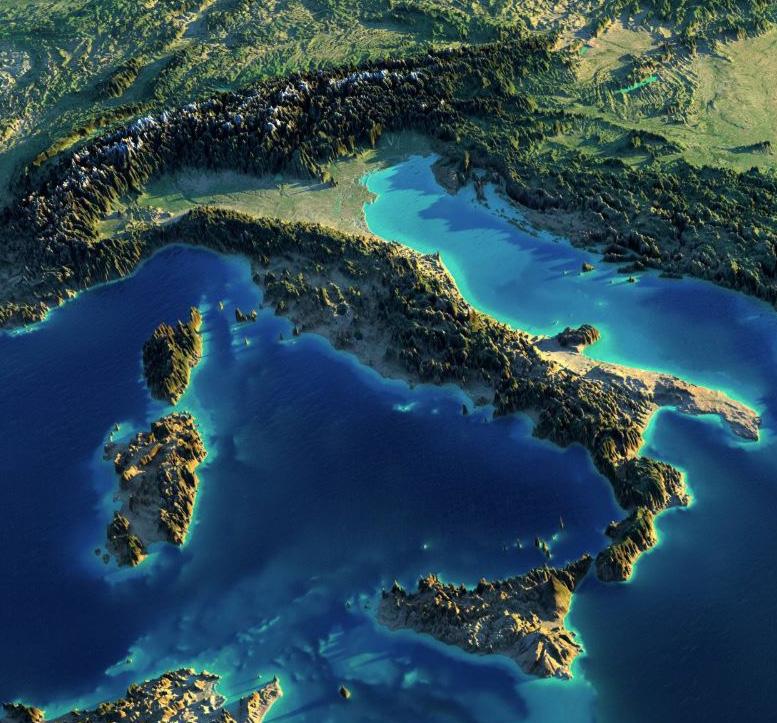
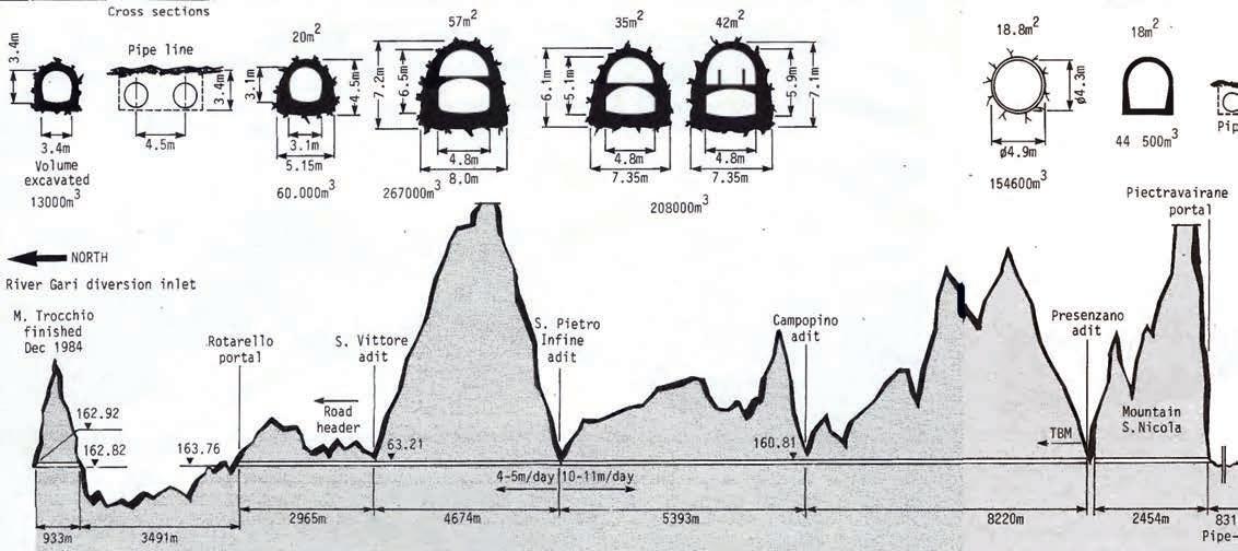
During severe summers, fresh water supply to the rapidly growing city of Naples and its satellite communities of Caserta and Cassino, is a major issue. To cope with the growing population, fresh sources of potable water had to be found. Following initial investigations in the 1960s, the most feasible plan was to divert and store the surge flows of the River Gari that is fed by rainwater run-off and the spring melt of heavy snows on the high mountains about 80km east of Naples.
• Client: Cassa per ii Mezzogiorno
• Contractors:
• Lot I Cogefar
• Lot 2 COVIG - Ghella/Vianini JV
• Lot 3 Grassetto
• Main Equipment supplier: Atlas Copco
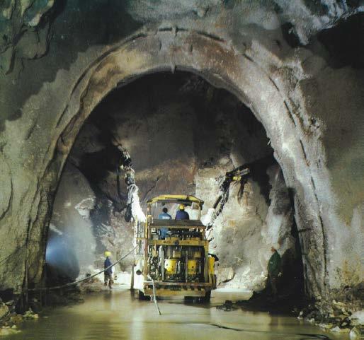
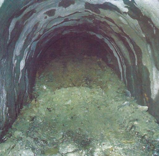
Left: Deformation measured as much as 200mm within 12hr of excavation; Right top: Severe squeezing ground conditions prevailed in several excavation headings; Right bottom: Atlas Copco provided equipment for drill+blast sections of the long aquaduct
This required tunnelling and lots of it to link the point of capture and its storage.
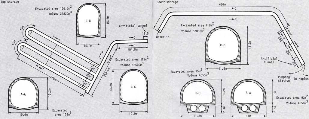
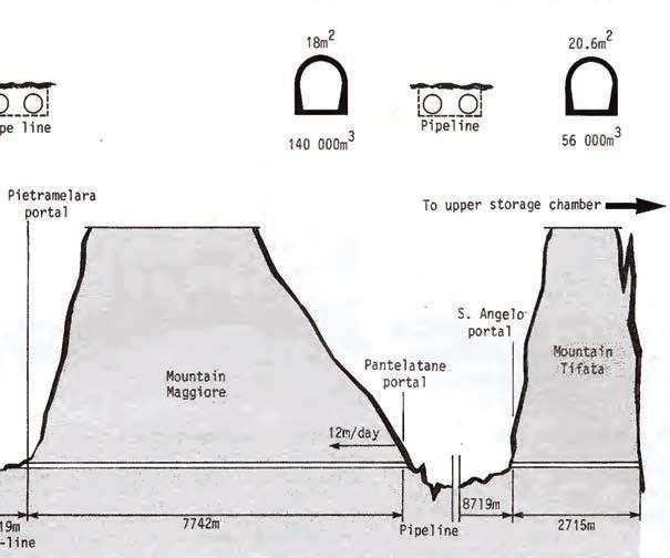
The first concept designed by a UK consulting engineer advocated driving one uninterrupted tunnel, but this would have taken too long as access points to drive additional adits were limited. The plan adopted in 1976 was to drive six shorter curved tunnels through the sides of each of the higher mountain ridges with connecting pipelines across the intervening valleys (Fig 1). Once captured, the water will be stored in two underground reservoirs formed by a grid of tunnels with various sections (Fig 2).
Of this 47.3km long aqueduct, approximately 35km is in tunnel through some of the youngest geological formations on the European continent. Mount Vesuvius, one of several notable active volcanoes in southern Italy, is no more than 30km distant. Approximately 75% of the tunnel line consists of limestone of a fairly homogeneous nature; 9% is in fractured rock with clay intrusions; and the remaining 16% comprises permeable rock containing vast volumes of water, much of which is under pressure.
Having accepted the plans in 1976, the client, Cassa per ii Mezzogiorno, a State committee for the development
of southern Italy, awarded the entire project in three lots in the early 1980s. The first 25.5km long section from the inlet to the Presenzano adit was awarded to the contractor Cogefar. Of this, 22km is tunnelled from seven headings. The second 30km long section from Presenzano to the storage galleries is in the hands of the Vianini/Ghella joint venture (COVIG) and is 13km is tunnelled. The third lot is two underground reservoirs. The upper gallery requires excavation of 217,500m3 of rock and the lower 82,200m3. Both of these are being excavated by contractor Grassetto.
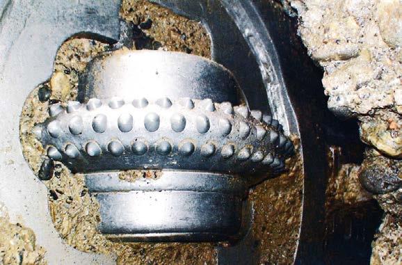
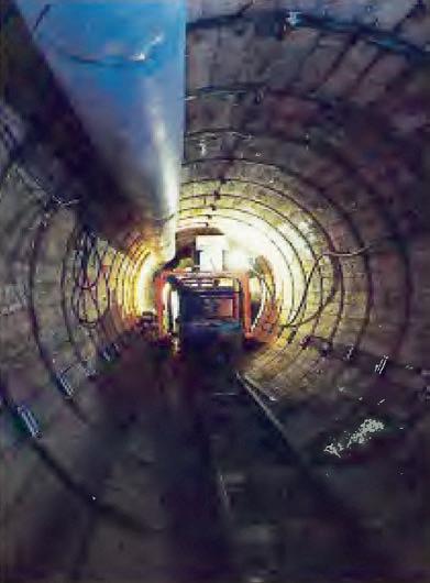
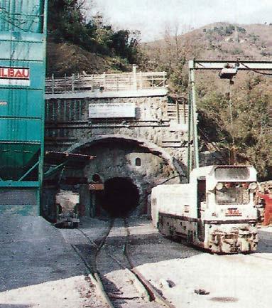
Three different tunnelling methods are engaged on the project. For the 8.2km tunnel from Presenzano adit to Campopino adit, Cogefar is using a 4.9m diameter Wirth TBM. The West German machine started in January 1984 and the best progress to date is 60m/24hr day. Average progress through the limestone and dolomite with a compressive strength ranging from 200-300 bar, is 30m/24h day. Cogefar is also using a modified Mavor roadheader to drive the 3km long section from San Vittore adit to Rotarello portal. But drill+blast is considered the most flexible and controllable method through ground of such varying composition and stability, and it was this aspect of the project on which a site visit in 1985
concentrated.
When equipping their contracts, all three groups chose Atlas Copco drilling equipment. This Swedish company has had a distributor in Naples for more than 30 years, with the Italian headquarters in Milan. From the Naples depot, a team of representatives assists clients with specific requirements, supplies machinery manufactured and shipped from Sweden and provides service back-up. An Atlas Copco Technician, in this case Adriano Bratti, is on call day and night to provide mechanical assistance and spare parts. This is particularly important on the Aquedotto della Campania Occidentale project where all contractors are working three 8hr shifts/ day on a 22 day/ month schedule.
For these long drives, the project managers for each of the lots ordered new equipment rather than using machines that had already prove their mettle on previous jobs. A list of all the equipment supplied by Atlas Copco to the project is listed in Table 1.
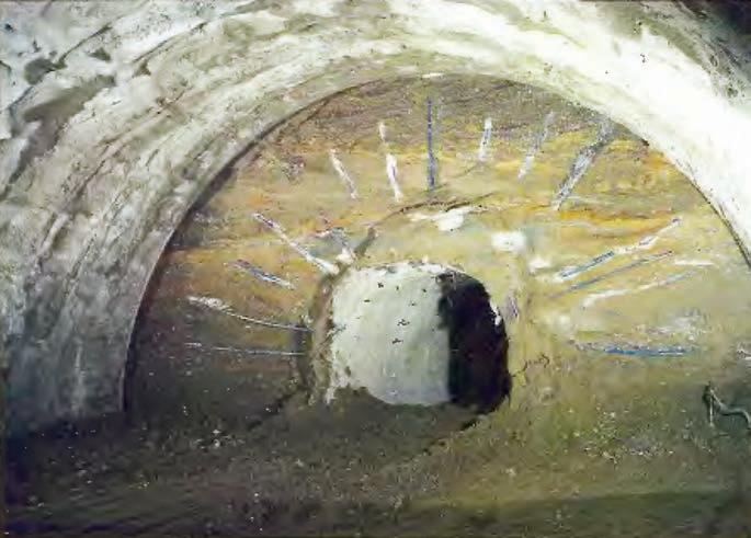
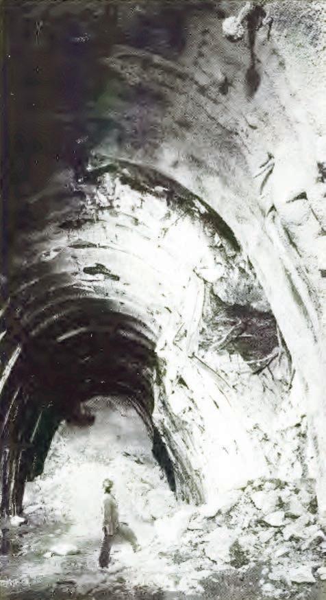
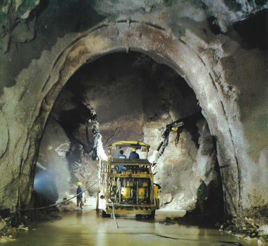
Of Cogefar’s drill+blast headings, the most difficult was south bound from San Vittore adit. Tunnellers expected to drive a relatively untroubled tunnel through homogeneous limestone, but very soon into the top heading of the 57m2 full profile they hit plastic clay. The walls of the tunnel deformed by as much as 200mm/24hr and 400mm in 12 days. Heave measured 1m in places. The regular wire mesh, steel arches and shotcrete employed in varying degrees to suit the prevailing ground conditions as immediate support, would not cope here. An unsuccessful attempt was made to anchor the steel arches with split set bolts. A second test was carried out using the Swellex bolting system. These bolts, combined with the steel sets, proved capable of withstanding
the enormous loads on the tunnel walls and the system has continued wherever plastic clay was encountered.
Not only was plastic clay a problem but also the face continued to squeeze and to tip forward making advance impossible. Following the success of the Swellex system on the walls, the same was applied to the face leading to the introduction of an unusual but effective method of tunnelling in such severe conditions. The sequence was as follows:
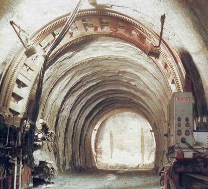
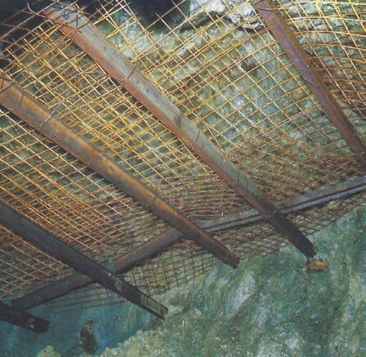
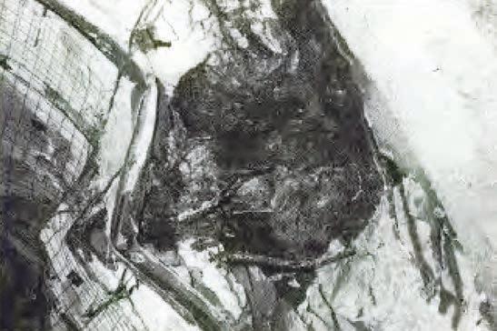
First, 50 x 3m deep holes were drilled into the face to receive 3m long Swellex bolts. The clay was then chipped and ripped-out with a 500mm long boom-mounted tooth of a hydraulic scaling jumbo. About 1.5m was excavated before the process was repeated (Fig 3), the exposed half of the bolts protruding from the face, all bent and contorted. This 1.5m advance was then reinforced with five HEA180 22.9kg/m double steel arches with an array of Swellex bolts between and finished with a layer of mesh and 250mm of shotcrete. Side-tipping Caterpillar loaders mucked the faces into fleets of Astra dumper trucks. In extremely bad ground, the tunnel is excavated to an
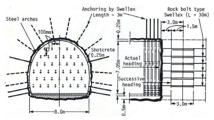
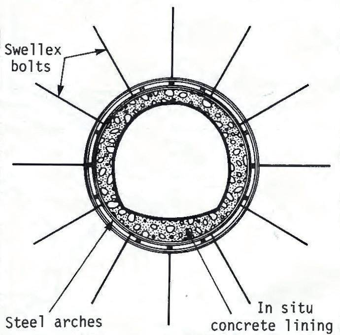
inherently stronger, more stable circular profile and supported with complete double steel rings anchored all round, including through the invert, with Swellex bolts (Fig 4). Advance rates of between 4-5m/24hr are accomplished with this method, leaving a stable excavation for the final in-situ concrete lining to be cast to the specified profiles along the tunnels.
With 50 Swellex bolts sacrificed for every 1.5m of advance, this is an extortionately expensive tunnel. No doubt other less expensive methods could be developed given time, but time was the one thing Cogefar did not have. As an immediate solution, to keep excavation advancing through such unexpectedly difficult conditions, the contractor was grateful for the particular characteristics of the Swellex bolts. These allowed the system to work where others failed.
Swellex bolts were also used extensively by Grassetto on the underground reservoirs but for different reasons. The geology here consisted mainly of heavily fractured blocky limestone in which rock bolts were essential. Unlike other rockbolts, Swellex, when installed, take on the exact shape of the hole. Water pumped into the hollow bolt, once in the hole, expands the tube into the irregular contours of the bolt hole, making it impossible to pull out. During the site visit, Grassetto had completed the top headings for both chambers as well as the first of two benches and work on the second bench had started on the lower chamber. In this excavated area, more than 18,000 x 3m long Swellex bolts had been installed. Special Boltec rockbolting rigs for mechanical installation of both Swellex and resin-anchored bolts were bought from Atlas Copco for the project.
Perhaps the most significant development on the project is the reintroduction of the use of foam as a flushing agent on the drilling jumbos used by COVIG on the Pietravairano 2.5km long drive through San Nicola Mountain. The friable dolomitic limestone of this area tends to flake and crumble as the drill passes through. This debris makes flushing difficult and obstructs adequate charging of the holes. By using the foam, or sulphonate as it is known in Italy, both problems are overcome.
The foam is made by feeding between 1.5-8 litres of biodegradable liquid mixture of anionic surfactants with each 454 litres (100 gals) of the jumbo’s water flushing system. As this mixture is pumped through drill steel to the bit, it creates the foam. The thicker consistency of the foam facilitates the flushing of larger flakes and chips of rock and stabilises the hole. Once drilled, the foam dries to form a thin film over the walls of the charge holes, supporting them and keeping them clear for unobstructed charging.
This system was first introduced in Italy about 15 years earlier for the drilling of deep water wells using down-thehole hammers where loss of flushing water through the ground was a problem. The sulphonate system improved the clearing of the hole. With the introduction of heavier pneumatic rock drills for tunnelling in the 1950s, serious flushing and crumbling problems occurred when drilling in highly fractured and incompetent rock. Many of these early pneumatic jumbos were first used on the transAlpine road tunnels linking Italy with the rest of Europe. It was Italian Atlas Copco technicians who successfully applied the sulphonate system for stabilising charge holes driven by pneumatic drifters in such rock types. The system was then taken up by other drilling jumbo manufacturers, particularly in the USA where further developments were undertaken.
With the advent of the hydraulic jumbos in the late 1960s and early 1970s, the sulphonate system receded into the background. Meeting the same drilling problems on the Pietravairano drive reminded COVIG Project Manager, Massimo Boncaldo of the system and with the help of his Atlas Copco serviceman, he successfully applied the technique to the three-boom Tunmec railmounted Promec TH533 jumbo, equipped with three new COPI038HD drifters.
During a visit into the face, the invert was covered with soap suds. The system was working well, although as Adriano Bratti pointed out, there are two main disadvantages; bit wear is substantially higher and it is harder on the jumbo over all. The drifter becomes overheated very quickly since the reduced amount of water flowing through the unit has a correspondingly reduced cooling effect.
In the 18m2 horseshoe-shaped profile of the drive, it took about 1.5hr to drill between 80-90 x 4.9m deep x 51mm diameter charge holes, the bit penetrating at an average 3.5m/min. Pull per round is approximately 4.5m and the resulting muck is loaded into 6m3 Valenti side-tipping muck cars by a 8HR Häggloader. A 120m long California switch allows passing of the two eight car muck trains.
COVIG excavated its 13km of tunnelling from four faces. Like the Pietravairano heading, each face is being drilled with a railbound Promec TH533 three-boom jumbo, fitted with COP-1038HD drifters. Mucking out at the Pietramelara and the Pontelatone headings differs from the Pietravairano setup, with muck loaded by rail mounted 8HR3 Häggloaders into HRST 90CL shuttle trains with eight cars in each. The best rate of advance were achieved on the Pontelatone drive through some of the best limestone on the whole project. Up to 12m/24hr day or three rounds of the 18m2 profile was the average on this drive. Progress is slowest on the Pietramelara and Sant Angelo drives where difficult clay conditions prevailed.
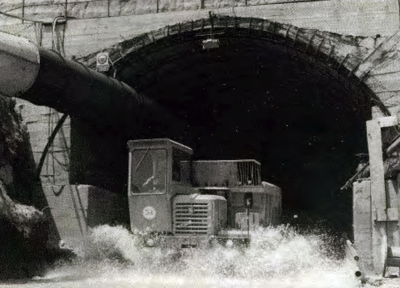
Perhaps the most unpredictable and astonishing, is Cogefar’s north bound drive from San Pietro adit. The mountain through which the twin-boom Boomer Hl 74, equipped with COP-1038HF drifters, had to make its way, is the most saturated area on the project. The geology consists of dolomite with clay intrusions. Water seeps along the interface of these two materials and in some places is under 8 bar pressure. Water, once trapped inside the mountain, has collected into caverns and an underground river. This has crossed the path of the tunnel three times in less than 500m. It was first encountered at 700m. To cope with the inrush of water, Cogefar had to temporarily dam the flow while a drainage channel was cut into the invert.
Work then continued until the 900m mark when the same river was met again flowing through a large 30m to 40m long x 20m high natural cavern. Not only did the river have to be channelled away in the invert as before, but an artificial tunnel had also to be fabricated in the open space of the cavern. This was achieved by setting formwork and pouring concrete over a steel reinforcement cage. This took many weeks to complete before advance could begin once more.
All seemed to be going well until the 1,116m mark, when the underground river was met for the third time and the same remedial work carried out. Franco Castellani, Cogefar’s geologist, promised, with a smile: “That river will not show up again on this drive.”
The water of the underground river is not to be wasted. Its 1m3/sec flow will be fed into the tunnel, which explains the odd configuration of this section of the aqueduct. In the 57m2 top heading and bench excavated profile, there will be a channel for the diverted flows of the Gari River 9km or so to the north, as well as a narrower channel to accommodate the underground river flow with an access inspection passage overhead.
The overburden between Campopino and San Pietro adits also consists of dolomitic limestone with clay intrusions and is heavily waterlogged. Here too groundwater is to be captured. Once the 42m2 tunnel passes through, 50m to 60m deep x 600mm diameter wells will be driven out into the surrounding rock to intercept the fissures and cracks down which the groundwater permeates. These laterals will feed into channels either side of the overhead inspection passage before joining the bulk flow in the lower part of the tunnel when it passes in to the circular tunnel of the Wirth TBM drive at Campopino.
The drive north from Campopino is being carried out by the sub-contractor Fontana for main contractor Cogefar, using a twin boom Boomer H 132. The first 933m long x 14m2 drive through Trocchio Mountain at the upstream end of the project was completed in December 1984, by sub-contractor Eugenio Riccio using a Boomer H115 jumbo. At the north bound heading from the San Pietro adit, Cogefar is using a Boomer H174 jumbo equipped with two COP1038HF drifters. Mucking-out is via a fleet of Astra dump trucks, loaded by a Poclain 1200 excavator.
Aquedotto della Campania is a demonstration of the skill of the Italian tunnellers, their acknowledgment of the importance of having the right equipment for the job, and in sufficient numbers, and the close cooperation they need and get from their equipment suppliers. Unfortunately, however, when on site, the contractors were somewhat in limbo. Although Cassa per ii Mezzogiorno is still managing existing projects, it was abolished in January 1985 and a new State committee is to take over. Very little of the extra time taken to complete the project (scheduled for Autumn 1986) will be as a result of mechanical failures or disputes with the tunnellers, but rather dur to client delays and upheaval When finished though, fresh water at a rate of 10.6m3/sec will quench the thirst of more than 3.75 million people living in Naples and Caserta and the 21 villages in the vicinity. n
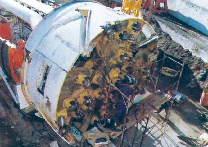
The Atlas Copco Jarva Mk18 hard rock TBM used to excavate the water supply tunnel with its overborers folded into the shield
CASE STUDY: An unusual project undertaken in Sicily, to drive a more than 7km long x 5.46m i.d. tunnel into the base of Mount Etna to tap a valuable source of potable groundwater to supply the nearby coastal city of Catania, required the development of a new efficient method of integrating immediate support with hard rock TBM tunnelling. Atlas Copco of Sweden and Ilbau of Austria appear to have achieved such a method with development of a new Jarva Mk18 TBM used for the project in Sicily.
1990 SITE VISIT REPORT
Four extra disc cutters on foldaway arms located behind the cutterhead of the Atlas Copco Jarva Mk18 TBM distinguishes this hard rock TBM from all others. They provide an effective method of overcutting the tunnel to allow installation of steel arches and other immediate support measures outside the nominal diameter of the bore.
The foldaway concept provides overboring only when necessary, allowing installation of immediate support to become part of the TBM procedure rather than the difficult and time-consuming setback it has proven to be on various projects that use the classical, open-type hard rock TBMs.
An overboring capability has long been a desire of hard rock TBM operators. Various methods have been tried but so far none has been totally satisfactory.[1] It was through close collaboration between mechanical engineers from the Austrian contractor Ilbau and the Swedish TBM manufacturer Atlas Copco that an effective system appears to have been developed on the Jarva Mk18.
The TBM is needed to drive a tunnel into the base of Mount Etna to tap a valuable source of potable groundwater to supply the nearby coastal city of Catania. The more than 7km long tunnel into the base of the mountain will tap rain water which seeps through the upper layers of porous volcanic deposits and runs along the interface with the original bedrock to emerge far out under the Mediterranean Sea.
The final length of the tunnel is as yet undetermined. The drive will continue until the groundwater flow reaches a
minimum of 2,000litre/sec. Once tapped, the water will be conveyed along the 5.46m i.d. tunnel in two 1.2m diameter steel pipes laid and embedded in the backfilled invert as the TBM advances (Fig 1). The upper part of the tunnel will allow passage of vehicles for inspection and maintenance. During construction, the pipes are used as ventilation ducts for blowing in fresh air.
The tunnel has a precast concrete, non-bolted segmental lining for internal finish rather than for structural support. This is also being erected as part of the tunnelling process but about 68m behind the advancing face where the vacuum segment erector is positioned on the back-up system designed by ROWA of Switzerland.
Since the 17cm-thick, 5.46m i.d. segmental lining will be installed throughout the 5.86m o.d. tunnel, it was essential that any immediate support needed at the face be installed outside the nominal o.d. and that an effective and integrated method be found of providing the necessary overbore.
Mount Etna has, during its years of activity, thrown up vast quantities of material. Lava flows which extend some 15km around the base of the volcano have cooled to form extremely hard basalt and pockets of loose rubble while layers of light, sponge-like pumis have been formed as lava has cooled around bubbles of trapped gases.
An attempt to complete the tunnel started about six years ago using drill+blast. But due to difficult geological conditions, the tunnel progressed only 800m from the single portal in three years before it had to be abandoned. Drilling of the charge holes proved difficult in the variable
Mount Etna emits smoke and steam as the tunnelling attack mobilises at its base
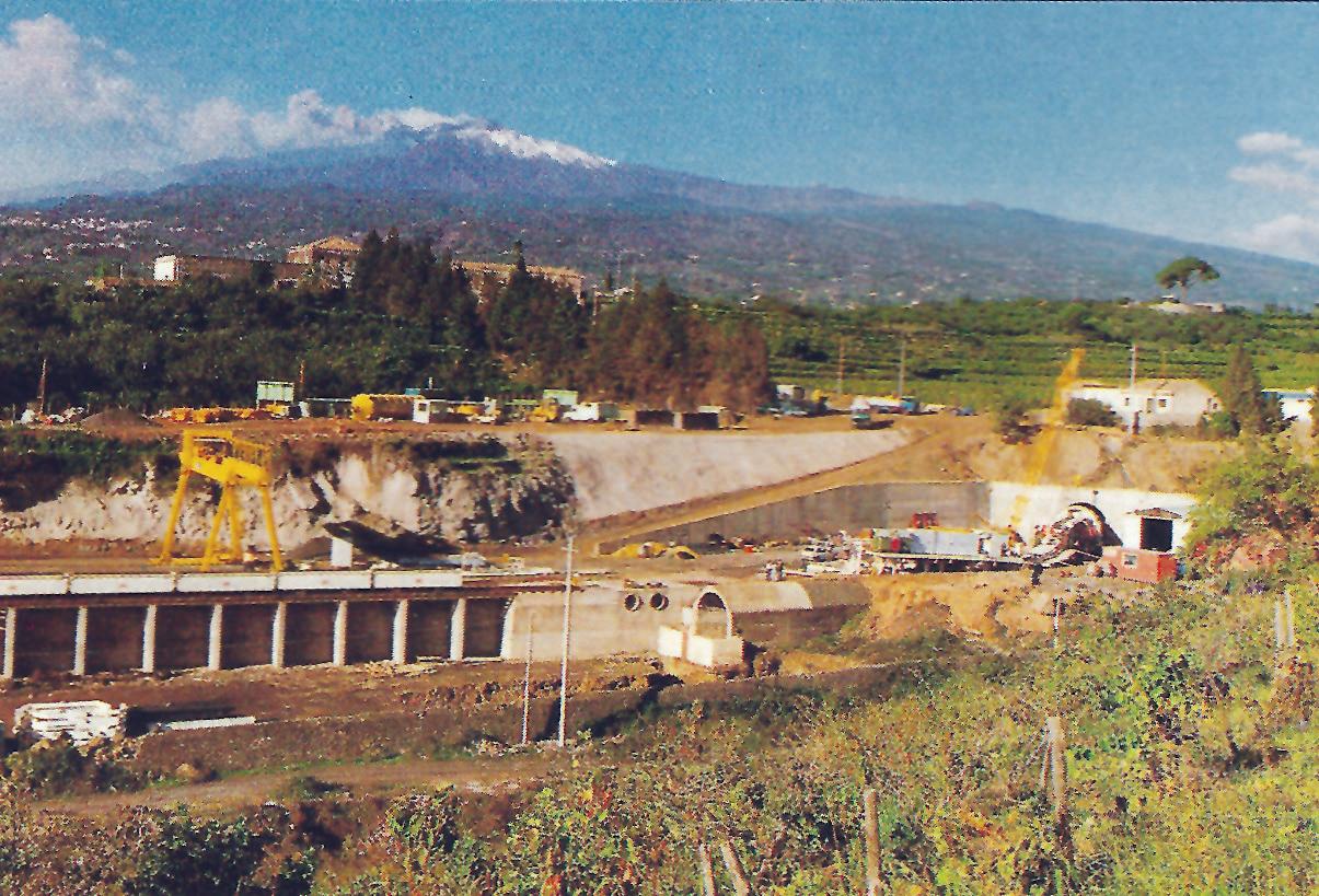
rock with the flushing water dissipating into the friable, porous rock and drill holes collapsing before they could be charged. Achieving an effective pull was also difficult, with each blast disturbing the surrounding rock and causing excessive overbreak.
The Galleria Drenante Piedimonte Etneo project, as it is known, is now being completed by an Italian consortium for the Regione Sicilia. Under a separate agreement, CO.GE.I, senior partner of the JV, engaged Ilbau of Austria to excavate the tunnel. Ilbau is well known in Italy for tackling difficult TBM tunnelling projects including the pilot tunnel for the Ponte Gardena railway tunnel and the Camporosso railway tunnel.
Ilbau has completed more than 90km of tunnelling using Jarva TBMs since it bought the first in 1981. As with the previous projects, the company has chosen the basic Jarva design upon which to build a new machine capable of working in the complex geology of the Etna project.
Unlike the more familiar Robbins-type TBMs with their horizontal grippers, Jarva TBMs have five grippers and the cutterhead is supported principally on a central torque tube rather than up front on the invert shoe. During the stroke the torque tube slides inside the main machine body which is held firmly by the grippers.
On the Sicily machine, the torque tube is actually 60cm longer than that found on previous Jarva TBMs to allow more than 2m of free space between the cutterhead and the first set of grippers at the full stroke position. This greatly facilitates the installation of immediate support such as steel arches, rock bolts and shotcrete. A retractable primary conveyor reduces equipment in the area to the torque tube only.
The longer torque tube concept was introduced on the Mk12 machine delivered to Ilbau in January 1989 for the 13.5km x 3.5m diameter water transfer tunnel for a hydroelectric power plant in the Alpe Devero in Italy. The risk of deflection online and level from the extra overhang is compensated for by a correspondingly stiffer torque tube.
In accordance with current TBM developments, the new Mk18 is also stronger and more powerful than previous Jarva machines. Compared with the Mk15 machine built in 1982 for Züblin for the Zillergründl project in Austria, the Mk18 has 60% more thrust, 100% greater power capacity and can advance 40% faster. To achieve this the Mk18 is more stable both statically and dynamically. Total deflection measured on a cutter saddle when high frequency shock loads of 10 to 15 times the average are applied, is less than 2mm, as on true hard rock TBMs.
This, plus the extra loads exerted by the overcutting facility, led to a 60cm thick solid cutterhead plate for the Mk18 which is much heavier than the sandwich-type cutterhead of the Mk15 for the same static stability but lesser dynamic stability. The thicker, heavier Mk18 cutterhead, weighing about 100 tonne, also has increased inertia for smoother running of the machine and fewer load variations in the drive train.
But it is the overboring system that really sets the Mk18 apart. The four hydraulically operated swing arms equipped with the overboring discs are set in the four quarters of the TBM circumference one behind the other about 7cm apart (Fig 2). When fully extended, each protrudes beyond the nominal diameter by a different amount. The first extends by 3.75cm, the second by
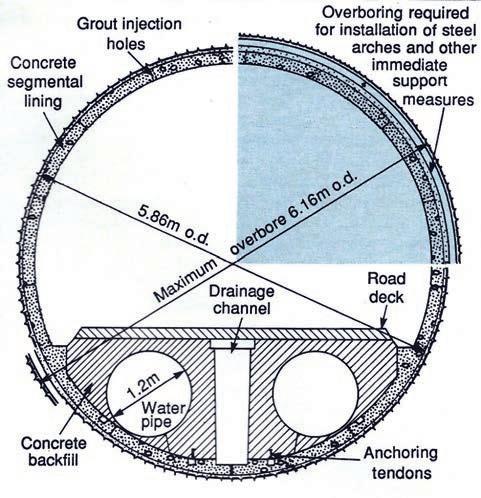
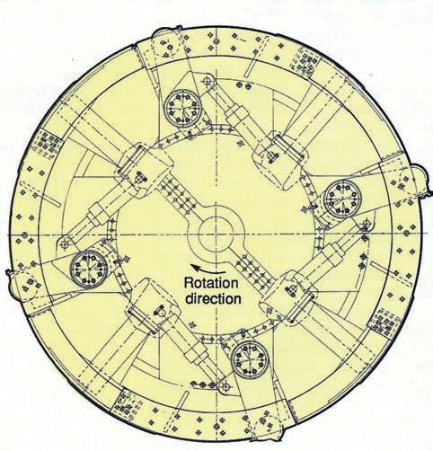
2. The Mk18’s overboring system: four swing arms with the over boring discs set in the four quadrants of the TBM
7.5cm, the third by 11.25cm and the fourth by 15cm, giving a maximum overbore of 30cm on the diameter.
When required, it takes about 6-7hr to set the overborers. This is achieved by rotating the cutterhead backwards and slowly applying pressure to the hydraulic cylinders which can apply almost 75 tonne of radial force to extend the arms. Once extended, the arms are supported by a dead backstop and locked mechanically into position. Forward rotation can then resume.
The cutters must be extended while rotating the cutterhead backwards because the hydraulic cylinders, powerful though they are, could not prevent the arms being ripped out of their sockets if extended during forward rotation. This was a lesson learned the hard way when the system was first tried in Sicily. It then takes about 1-2hr to retract the arms when they are no longer needed. This is achieved with the cutterhead at a standstill.
Many TBMs are fitted effectively with hydraulic motors for hydrostatic drive but, due to the inertia of hydraulic motors, they must take all load fluctuations as part of their normal torque. Atlas Copco has come to the conclusion that this is not the system for the future of high-performance hard rock TBMs. In the Mk18 it has therefore adopted electric AC drive motors.
AC drives of today are of the pulsewidth modulation (PWM) type whereby the output voltage is built up of many small pulses. This gives a virtually smooth sine wave of almost any frequency or voltage. The speed and torque of the induction motors are therefore controlled in a wide range below or above normal speed. With PWM variable speed drive, the induction motors can be controlled from zero to full speed with constant full torque and exceed full speed by up to 200% with constant full power.
This is achieved with very little loss in the motor or in the variable speed drive (VSD). In addition, there is no surge of current during start up on full torque, no need for jog
motors or automatic speed and torque controls and no need for an overload protection system.
In Sicily, the added cost of the AC VSD was justified since the objective is to operate at high speed in stable homogeneous rock and at slower speeds in poorer rock and when the overborer is needed. The TBM is fitted with six 250kW motors with four pole induction of 660 volt at 50Hz and six VSD units supplied by ABB of Finland, one for each motor.
A tendency of these motors to stall in blocky ground was overcome by fitting tachometers on the motors. This is particularly significant since in Sicily power for the entire job site is generated by five CAT 800kVa diesel generators. Without the variable speed drive on the TBM, the project would have needed more generators.
The Jarva Mk18 was launched in October 1989. To midOctober 1990 it had successfully excavated some 1.9km through extremely variable ground. Ground conditions have been at least twice as bad as predicted in the geological report, according to Eric Kapeller, Ilbau’s Site Manager in Sicily. “We are having to carry out much more immediate support than we had anticipated,” he said.
For immediate support purposes, the geology is divided into six classes based on the official geological report, much as it is for a regular NATM-type project. Shotcrete, wire mesh and rock bolts, used in various combinations, are installed where necessary from work stations on the TBM backup.
It is only in rock class VI that steel arches are necessary and the overboring facility is required. The TBM also allows for application of shotcrete, wire mesh and rock bolts immediately behind the cutterhead in the 2m space between the cutterhead and the first set of grippers and even in front of the cutterhead. An ample sized door in the cutterhead plate allows adequate passage of personnel and portable equipment. With the long torque tube, it is possible to apply immediate support behind
the cutterhead at full stroke, then pull it back to allow manual work at the face under the protection of the supported vault.
Rock bolts used on the site are almost exclusively of the Swellex type from Atlas Copco. “To date we have used 5,400 Swellex units of 1.8m to 3m long,” said Kapeller. Bolts are usually installed in combination with wire mesh and 10cm to 20cm of shotcrete. About 80% of bolting is installed using pusher legs close to the cutterhead with the rest installed using two rock drills mounted on the backup.
“We chose Swellex bolts mainly because we wanted a fast bolting method to keep up advance and avoid delays,” said Kapeller. “Swellex bolts are easy to install, and this is particularly appreciated in this non-homogeneous ground.” A special conical tip fixed to the upper bushing allows for the bolts to be inserted through drill boles which may have partially collapsed, a problem that is often faced when drilling in poorer rock.
“Up to now, we have used the overboring facility four times,” said Kapeller. “These add up to about 300m of the total 1.9km we have excavated. The worst situation is in mixed face conditions with hard rock in the bottom and softer loose material in the crown. In such cases, we go ahead of the TBM and have to excavate the loose material carefully by hand, keeping the shotcrete ready at all times.” Of the immediate support applied to date, 90% has been installed up front and of this, about 70% installed in front of the cutterhead.
Once the face is stabilised, the TBM can advance and cut the hard rock in the invert. Any resulting overbreak is filled with shotcrete to provide a uniform surface against which the internal segmental lining is installed. Overbreak of up to 60cm has been recorded.
The steel fibre reinforced concrete segments are cast on site. There are seven segments in each l.2m wide nonbolted ring. The top two segments act as the keys and, once grouted into place, the 17cm thick segments form the 5.46 i.d. finish of the tunnel.
Trains of eight 8m3 Mühlhäuser side dumping muck cars haul the muck. A special tooth is fitted to the cutterhead to scoop up the muck from the invert when the overboring system is employed.
“Even though we still have more than 5km to go on this tunnel, we can already say that we have what we believe is the very best TBM available for the job,” said Kapeller. “We can cope with any type of rock we meet and in a clear run in good quality hard rock of up to 180MPa, we have achieved up to 26m in two 11hr shifts. Our best advance so far was 131m in a six-day run.”
Unfortunately, clear runs in good rock are rare in the complex geology around Mount Etna and the best weekly average so far has been 21.8m, with a daily average of 12.12m in September.
When asked about cutter wear, Kapeller said that wear was difficult to gauge since cutters were having to be replaced more often as a result of damage rather than wear. Blocks of rock falling out of the face cause high peak loads on the cutters which damage the shafts and the bearings. This problem has since been solved by
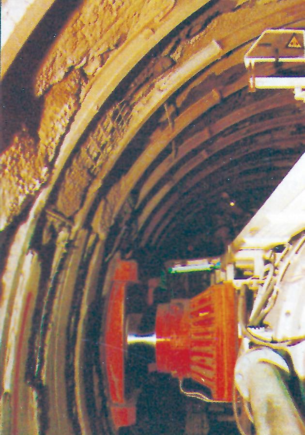
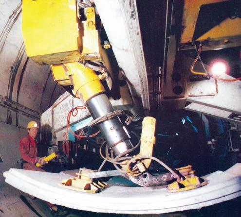
welding wedges on the cutterhead in front of the cutters which deflect the blocks and protect the lower part of the cutters and the saddles.
All in all, Ilbau has a flexible TBM in the Atlas Copco Jarva Mk18 and, like its previous Jarva machine, is surely destined for many kilometres of tunnel boring in the years to come. In Sicily, where the NATM, segmentally lined tunnelling and TBM tunnelling are all being used on the same tunnel drive, the machine has proven its flexibility to fit in with whatever is required in the conditions of the moment, yet powerful enough to perform as a top-rate TBM when in its hard rock element. n
CASE STUDY: TBM pilot tunnels preceding full section excavation have become the norm in Italy with the pilots revealing the exact nature of the ground and allowing more accurate specification and estimation of full profile excavation and support requirements. With this development, TBMs of higher specification and the ability to apply immediate support as required to limit progress delays but it was an old faithful 3.6m diameter TBM applied to drive the pilot for a new road link near Genoa in the early 1990s.
1993 SITE VISIT REPORT
For TBM tunnelling, the Alpine and Appenninica geology of Italy is both good and bad. The relatively hard rock suits TBM tunnelling but volcanic and seismic activity over the millennia has rendered it highly fractured and disturbed, requiring a relatively high degree of support. TBM utilisation in Italy can be as low as 30-50% with rock support and reinforcement accounting for 50% or more of the total production time.
When rock support is required in conjunction with a TBM operation, consideration must be given to the type of support required and how quickly it must be installed. "In highly fractured rock, reinforcement, principally rockbolts, should be installed as quickly and as close to the face as possible," said Dr Ernst Büchi, senior geologist with Geotest of Switzerland and a recognised authority on TBM tunnelling in rock. "However, for most types of TBMs, installing support close to the face requires TBM downtime. Given the relatively high cost of TBM tunnelling, these halts in progress are a major concern for both the contractor and the client. Developments in the speed and ease with which support can be applied to improve TBM utilisation, limit machine downtime and increase productivity, while at all times respecting safety requirements, is of interest to all parties involved in TBM tunnelling in disturbed rock."
One of the most successful TBM tunnelling contractors in Italy is the Italian subsidiary of Austrian contractor Ilbau. Ilbau has excavated more than 100km of TBM tunnels with more than 50km of this in Italy. Today, Ilbau has five active contracts in Italy, including two pilot tunnel jobs.
In early February 1993, a site visit was made with Dr Büchi to visit the Ilbau pilot tunnel project in Alassio where its 3.6m diameter grand old marathon Jarva TBM is excavating the pilot for the subsequent 2.4km long two lane road tunnel on a new link road between Alassio and the four-lane highway autostrada built in the 1960s which passes in and out of many tunnels and over many bridges on its parallel route with the Italian coast near Genoa. As with all TBM projects, the aim at Alassio is to apply adequate support while at the same time limit TBM stoppages and maximise productivity.
Jarva TBMs
In this respect, the type and configuration of the TBM, as well as the type and location of support required, has
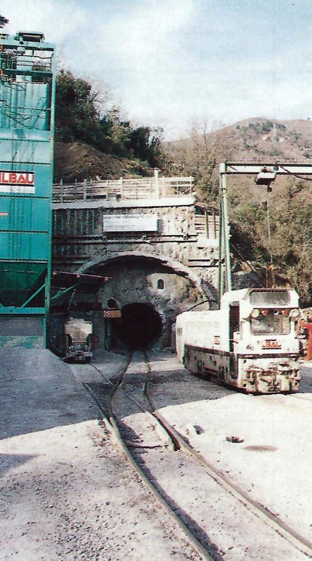
a marked influence on tunnel progress. As a leading TBM tunnelling contractor, Ilbau owns the largest fleet of Jarva TBMs. Of its eight 3.5m to 6m diameter TBMs, seven are Atlas Copco Jarva machines. As a major TBM manufacturer, Atlas Copco is conscious of the
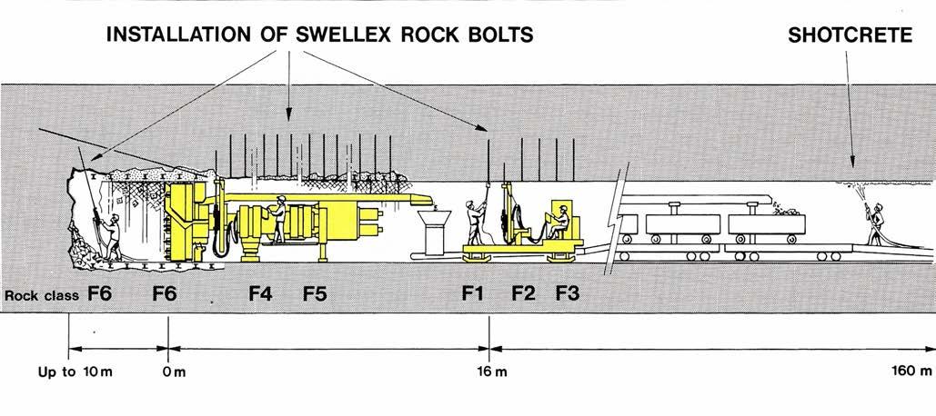
Fig 1. Major developments in TBM tunnelling technology concentrate specifically on a more successful combination of TBM excavation and the need to install rock support or apply ground consolidation measures
TBM downtime dilemma, especially when combined with the need to install immediate support. With each new generation of Jarva machines, this is a significant
design criterion. Atlas Copco's acquisition of The Robbins Company of the USA will further impact the future design and development of TBM technology.
Table 1. The seven rock classes and corresponding support measures developed by Ilbau from the Austrian Onorm rock classification system to combine NATM type support with TBM tunnelling. The chart relates specifically to a 5.8 m diameter TBM tunnel and specifies the type of support required and how quickly and where it is to be installed
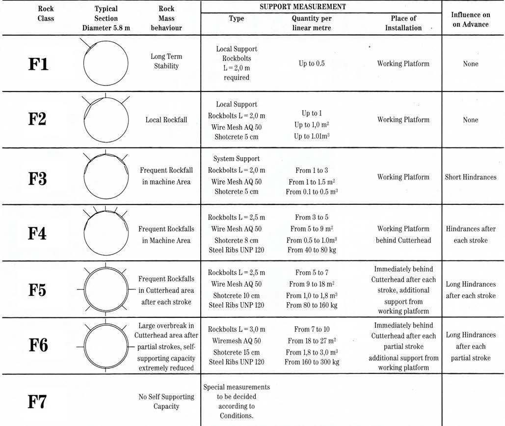
Jarva TBMs have a flatter and shorter cutterhead than other TBM designs and a relatively clutter-free torque tube area. This allows ground support and consolidation measures to be installed immediately behind the head and very close to the face. In more recent models, Atlas Copco has added several modifications to assist support installation. A retractable primary conveyor improves accessibility close to the tunnel face, particularly in the crown area. Longer torque tubes of up to 1.5m strokes provide more space and can incorporate fixed hydraulic drills to replace slower hand-held drilling equipment. Jarva machines of 4.5m diameter and more can also be provided with an overboring option. Disc cutters mounted on hydraulically extendable arms provide an increase of the bored diameter by up to 300mm to allow installation of steel rings and other full support measures without reducing the nominal bored diameter. Such as system was fitted to the Jarva TBM Itbau used to excavate the water tunnel in Sicily (see p26).
More powerful machines providing up to 19,000kN thrust and 8,000kNm torque (Jarva MK 27) with additional developments in disc cutter and mounting designs to allow up to 35 tonne load/500mm diameter disc, bring
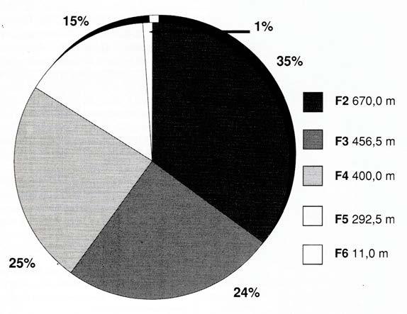
Fig 2. Rock support accounted for approximately 50% of TBM downtime on the Alassio pilot tunnel with most in support types F2 to F4, and 15% in type F5
TBM-driven pilot tunnels preceding full section drill+blast excavation appears to be the norm rather than the exception in Italy. In its unpredictable geology, most larger section road and rail tunnels from as short as 2km or so start with a pilot.
Pilot tunnels are favoured by Italian clients for several reasons, not least of which is that they reduce substantially the likelihood of excessive claims and dispute situations. The pilot reveals the exact nature of the ground allowing more accurate specification and estimation of full section excavation and support requirements. Fault zones and areas of particularly difficult ground can be consolidated prior to full section excavation and the pilot will drain and therefore reduce volumes of ground water.
Pilot tunnels have additional advantages. Excavation to full section, or reaming, becomes a faster, more controlled, less expensive and less risky operation than full section one-pass excavation. For a drill+blast reaming operation, pilots serve as huge burn or cut hole which effectively halve the amount of explosives required/m3 of muck. With a ratio of about 1:10, the charge-hole drilling time is consequently reduced, especially since most charge holes in full section excavation are concentrated in or near the middle where the pilot is now located. Less explosive/round creates less blast damage to the surrounding host material and reduced vibration causes less disturbance when working close to urban and residential areas.
Full length pilots also assist ventilation during full section excavation. Pilots are generally located about 2m from the vault of the full section excavation line to allow for temporary rockbolt support in the pilot crown yet high enough to avoid blocking off the ventilation benefit with the reamed muck pile.
In broad terms the cost of a pilot tunnel/linear metre is about 1:5 to 1:7 the cost of the reaming excavation with its necessary support and final lining requirements. While pilots bring major advantages to the full section excavation, their costs must be controlled to stay within a narrow window of cost effectiveness. Ironically, in potentially more difficult ground where a pilot would be most useful for geological investigation purposes, their price, due to necessary support measures and risks involved, render them non-cost effective. Work usually goes ahead on a full section onepass system in such cases, without pre-excavation of a pilot.
Support for in-line pilot tunnels is of a particular concern. It must be sufficient to secure the safety of workers during pilot construction but needs only to support the pilot until reamed. As such, it is the time taken to install the support elements and the impact this has on TBM productivity, which is of most concern, particularly when installation is required close to the face and involves TBM downtime. The ability to install support without causing TBM downtime is crucial. Failing that, the speed of installing rockbolts and other support elements is critical to limit expensive downtime as much as possible.
In the past, pilot tunnels in Italy were awarded usually as lump sum contracts. Today, in efforts to share the risks more equitably, llbau, for one, has convinced clients to work on unit cost type contracts, based on a fixed price/ tunnel metre, plus unit costs for installed support using its table of rock and support classes, plus a lump sum for site mobilisation. More effective methods of combining support installation with TBM tunnelling will further improve the cost effectiveness of TBM pilot tunnelling and TBM tunnelling in general.
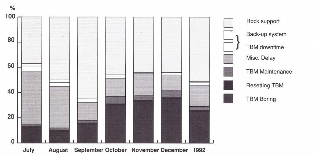
3. Analysis of rock support installation and recorded TBM downtime
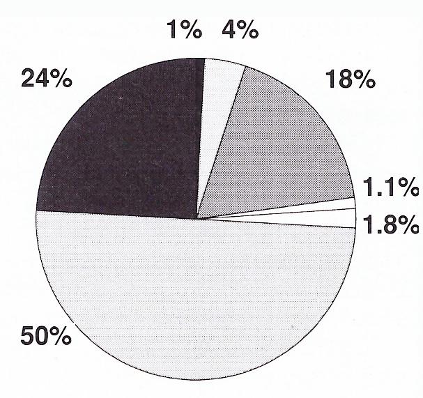
production rates in competent rock of up to 6m/hr and up to 100m/day well within reach.
Other developments in the operation and monitoring of TBM functions have dramatically increased availability to the point where labour regulations and practices now have a greater influence on TBM utilisation than mechanical breakdowns.
With a stroke of 1.2m and a cutterhead body of about 2m, the Jarva MK 12 being used at Alassio allows installation of immediate support within 3m of the face. However, since this requires TBM downtime, it is kept to a minimum with most support work carried out concurrent with TBM advance from the platform on the trailing backup some 16m back (Fig 1). This also allows installation of truly radial rockbolts in the crown.
At Alassio the owner is Autostrada dei Fiori SpA, the independent owner and operator of regional toll roads, and Ilbau's subcontract is with Villa Nova 92 BIS, a group of local contractors building the full road link. As part of its contract, Ilbau is responsible for the design of the pilot tunnel support.
For
with its client, Ilbau has developed a rock class and support measurement system specifically for TBM tunnelling (Table 1). Adapted from established Austrian practice, the table considers the most appropriate rock support for given rock conditions and specifies how quickly and where the support should be installed. In better rock conditions (Classes F1, F2, and F3) bolts, mesh and shotcrete can be installed from the working platform without interrupting TBM progress. In Classes F4, F5, and F6, support must be installed as close to the face as possible and requires a stop in TBM advance.
Class F7 constitutes rock with no self-supporting capacity. In such conditions, ground consolidation techniques or full lining support with ribs and timber lagging or bolted liner plates are required. In zones of extremely difficult ground, consolidation and support measures may be required ahead of the TBM.
"Because of the potential impact on TBM utilisation, the payment schedule for rock bolting and other support requirements is based on where it is installed, with higher unit prices for support installed close to the face requiring TBM downtime", said Ilbau's geologist in Italy.
At Alassio, the client has specified the use of Swellex for rock reinforcement and is supplying these to Ilbau for installation. Although perceived by many as more expensive than alternative rock support and reinforcement systems, the unit price of Swellex becomes substantially less significant when compared with the costs saved in labour and limited TBM downtime. The easy handling of Swellex is preferred by most tunnelling crews and its geomechanical properties, speed of installation and additional advantages are winning over consulting engineers, clients and contractors.
There is little simpler or easier in the tunnelling industry than the installation of a Swellex bolt. The deflated or folded bolt inserted easily by hand into the bolt hole and inflated with the high-pressure water pump is a one-man operation taking just minutes. When inflated, the bolt is
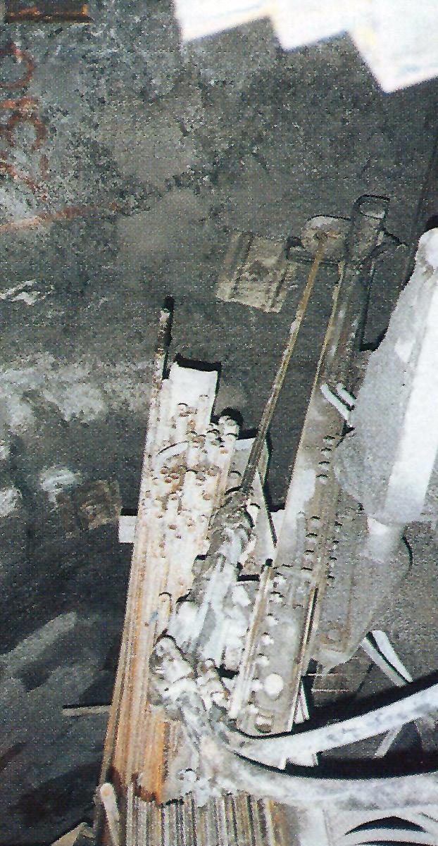
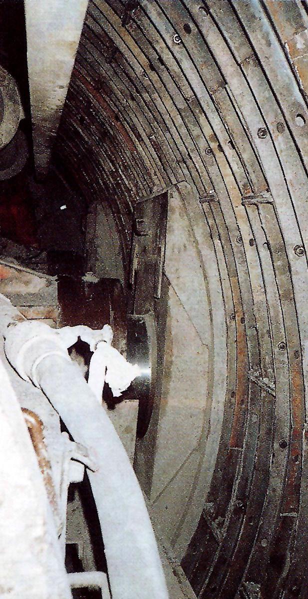
left: Once the bolt hole is drilled, Swellex bolts are inserted without mechanical assistance and inflated with a handheld high pressure water pump; The
gripper pads apply directly against steel liner plates used to line a section of
immediately operational taking load along its length. This epitomises the term immediate support. Installing cement grouted rock bolts can hardly provide immediate reinforcement when cement curing time is required.
Swellex is particularly advantageous in small diameter and pilot tunnels where the diameter determines the maximum bolt lengths. The maximum length of alternative systems which require mechanical installation is limited to about half the tunnel diameter. That is, the length of the bolt resting against the tunnel wall plus the length of the hammer needed to drive it home. With easy hand installation, the length of a Swellex bolt can almost equal the tunnel diameter.
At Alassio, the geology comprises mainly soft, dry, nonabrasive calcareous marls with defined bedding, some clay content and zones of fractured and blocky rock. Rock quality can change very rapidly and often from stroke to stroke. Such changes are felt by the TBM operator through changes in applied thrust. He advises the foreman who
then decides on the support required.
"Given the higher speed of advance, the limited space, and the more complex method of muck handling, there is little scope in a TBM tunnelling operation to completely modify the support design when facing changed rock quality," said Büchi. "It is rare to see different types of bolts or different steel arches on a TBM pilot tunnel site. The basic bolting and arch support concept chosen at design stage is used in various combinations with mesh and shotcrete to cope with the range of anticipated rock conditions. As a rock reinforcing tool, Swellex is effective over a wide range of rock and soil types. In Ilbau's table of rock support for instance, Swellex is applicable in all classes from class F1 to F6. By using Swellex there is no need to keep a stock of any other types of bolts. Together with its ease of application and immediate support potential, Swellex has the all-round advantage."
In the 1,918m of the Alassio pilot completed by the end of December 1992, support was mostly of types F2 to F4
with 15% in type F5. Swellex reinforcement over the same length averages about four bolts/linear metre, 60% of which are 1.5m long with 40% at 2.1m. "Support installed in the Alassio pilot tunnel is about 10% more than we originally estimated, with a corresponding 10% reduction in productivity."
Swellex, wire mesh and shotcrete were used in fault zones where two or three small but obvious roof falls had occurred. In other areas thin layers of shotcrete had spalled off, with small falls of rock from bedding planes. These create no serious safety hazards and confirm that Ilbau is installing adequate support for a pilot tunnel - not too much, not too little.
When originally specified, the support was designed to secure the pilot tunnel for about two years after which excavation to full section was to begin. Due to economic constraints, full tunnel excavation may now be delayed. The pilot may have to stand for a few extra years. Under the two-year design specification, some 10 linear metres needs some extra support while about 100 linear metres in total will need extra support to extend the pilot's design life to about five years.
To monitor the quantity and quality of support installed, the client's consultant geologist visits the site about twice a week. In addition, the consultant monitors geotechnical instrumentation installed by Ilbau. Along the tunnel there are 15 convergence measuring stations and three stations containing three groups of 1.5m, 3m, and 4.5m long extensometers in the crown and into each wall, as well as five tangential and five radial pressure cells. Data gathered will greatly assist design of the full tunnel support and final lining requirements.
During the site visit in February 1993, the 3.6m diameter TBM had completed 2,300m of the total 2,472m tunnel from the boring start date of July 1992 and working 127hr/ wk on a 2 x 11hr shift/day, 5.5 days/week. Breakthrough occurred as scheduled at the end of March 1993. The best advance recorded (in October 1992) was 53m/day in rock Class 2 installing 110 bolts mainly from the backup platform. This is close to the optimum 60m/day achievable in a short tunnel operating a single track muck hauling system. The average was about 15m/day. When on site, the tunnel was passing some 35m beneath a highway where the client specified the installation of bolted liner plates over a 100m length. The liner plates are installed in the torque tube area and the TBM grippers engage against the plates without causing damage.
The Jarva MK 12 being used on the job was commissioned in 1982 and was the first Jarva TBM sold after the USA company was bought by Atlas Copco in 1978. Today the machine is into its 43rd tunnel kilometre and shows little sign of being retired. Other than replacing worn cutterhead spokes and fitting a new bearing between jobs, the TBM components are basically the same.
The machine is powered by 4 x 150kW electric drive motors (600kW total) providing a maximum 635 tonne thrust. The cutterhead has a fixed rotation of 10.5 rev/ min and is dressed with a central bank of four 12in cutters and 19 face and four gauge cutters of 16.5in diameter. The installed thrust provides a maximum load of about 25 tonne/cutter. Of this, about 50% was required to drive through the marl at Alassio with each 1.2m stroke taking about 17 min on average to cut. Wear in the soft marl was
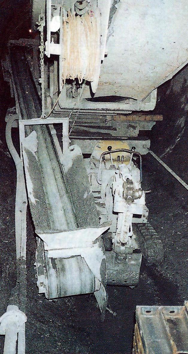
A special invert scraper has been included on new generation Jarva TBMs to replace the mini backhoe
limited to about 30 cutters over the whole 2.5km length.
According to Stefan Trenkwalder, Ilbau's plant manager, the only problem with the TBM is its grand old age. It is therefore reserved for short tunnels in softer rock. Later Jarva models have automatic thrust control systems and variable speed electric drive with a higher 12.2 rev/min cutterhead rotation. This provides more torque, greater penetration and higher production rates. There is also no need to jog motors for start up on full torque. Cutters on this MK 12 are limited to 16.25in by the size of the saddles. Having completed this latest job, the old marathon TBM may yet be made ready for the next task wherever and for whatever that may be.
Meanwhile, new generations of TBMs in conjunction with easily installed rockbolting systems such as Swellex strive for more cost-effective methods of combining hard rock TBM tunnelling with immediate support. The calculation is simple. If Swellex can contribute a 10% decrease in an average 50% of TBM availability spent on rock support, this would increase TBM utilisation by 5%. In a 20hr production day, this is equivalent to an extra production hr/day. If only 50% of this is utilised boring at a potential 4m/hr rate of penetration, this is an extra 2m/day. A goal well worth striving towards for all parties concerned. n
CASE STUDY: A delicate and cautious underground operation based on excavating in-line TBM pilot tunnels was adopted to avoid cut-and-cover construction of Milan’s third metro line through the busy commercial centre of Italy’s principal northern city. The project was among the earliest applications of TBMs for settlement-controlled metro construction.
Past experience has shown that excessive ground settlement is the greatest risk associated with large profile tunnelling under the busy narrow streets of central Milan. A receding water table in the area has taken with it fine infilling sands, leaving unconsolidated gravels which require extensive ground treatment prior to excavation. When Metropolitana Milanese (MM) - the public corporation established by the Municipality to be responsible for the planning, design and construction supervision of Milan's Metro on a turnkey basis - began working on the city's third line, a totally new tunnelling concept to those used on the previous two lines had to be developed.
All of the first Red Line was built by cut-and-cover. Started in 1957, it took six years to complete with three years of intolerable traffic chaos while the inner-city section was under construction. Most of the second Green Line was tunnelled using the top heading and benching method, but in some cases, surface settlement of ±100mm, 20 times the 5mm specified theoretical tolerance required for the third line, caused many costly problems. Much of the third 10.2km long Yellow Line, designed to link the Rogoredo Romana and Centrale mainline railway termini, and intersect with the Red Line at Duomo and the Green Line at Centrale, is being constructed under main roads by cut-and-cover (Fig 1).
But for the central 3.5km from Turati Station in the north to Medaglie d'Oro Station in the south, a completely underground operation is not only necessary to avoid disruption of the city's traffic flow and daily activities, but also because the narrowness of the streets in this, the oldest part of the city, would never accommodate the cut-andcover method. As it is, in order to keep the metro system directly beneath the streets, as is the usual accepted practice, the tracks have to be on a double-deck configuration for most of the tunnelled length.
Public inconvenience and damaging settlement on
• Client: Metropolitana Milanese (MM)
• Contractor: Lodigiani Consortium
• TBM manufacturer: Lovat
• Contractor: Torno Consortium
• TBM manufacturer: Bade & Theelen
this central section of the Yellow Line was to be further avoided by initiating the work from pilot tunnels driven approximately 9m below the surface. Once excavated, these will afford the space in which to carry out a more effective and tighter controlled ground treatment programme and even the limited traffic disruption of a surface treatment installation operation would be avoided. But excavation of these pilot tunnels has proved a delicate operation in itself.
When MM released the contract documents for the 3.5km underground section, it specified a complex programme of pre-stabilisation for the excavation of the pilots. This involved the formation of a horizontal ring of nine 600m diameter x 8.5m long concrete piles, using the jet grouting system. Following this, some 6m of the interior would be
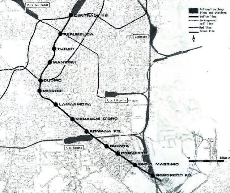
removed and the tunnel supported by a 100m thick layer of shotcrete before the process is repeated. Because ground movement is such an important consideration, a sophisticated electronic alarm system attached to the buildings along the route was also specified. With this equipment, ground movement of more than 5mm triggers a siren to warn of the danger. It was to these specifications that all competing contractors had to bid and for which two contracts were let.
The first 2km long contract from Medaglie d'Oro to Duomo was awarded to Lodigiani in JV with three local firms. The second 1.6km long section from just north of Turati to Duomo was won by Torno in joint venture with two local contractors.
From work already accomplished using the latest in fullface TBM technology, particularly in urban situations, the winning contractors were convinced that the pilots could be driven with a full-scale TBM without prior ground treatment. This would not only eliminate the cost of expensive pretreatment materials but also drive the pilots
much faster. Convincing MM of the TBM option however, was not easy. It was only after long discussions and the willingness of the contractors to stand by their convictions and agree to carry all risk for the method, including the machinery and any resulting settlement, did MM give reluctant permission for the first contractor, the Lodigianiled JV, to use a TBM. Both pilot tunnels are now complete, and the performance of the machines used by the two contractors differed enormously, bearing in mind that the acid test was to keep ground settlement within the ±5mm tolerance.
For its pilot tunnel, Lodigiani chose a 3.3m diameter Lovat shield and launched it at the bottom of an 11m deep shaft just north of Medaglie d'Oro Station to drive the 700m north to Lamarmora Station. The 1,500 tonne thrust capacity machine excavated the loose alluvial soil at an average advance rate of 12m/10hr day. A train of 3.5m3 Swiss Joung muck skips removed the excavated material. An erector arm on the TBM mechanically-built an immediate temporary lining of steel rings and wood lagging, each length erected in approximately 25min.
Left: Lamarmora open cut station box in the centre of Milan; Right top: Hole-through of the Lovat TBM in the loose dry alluvial soil; Bottom: Cutterhead of the Bade & Theelen TBM as it prepares for its next drive
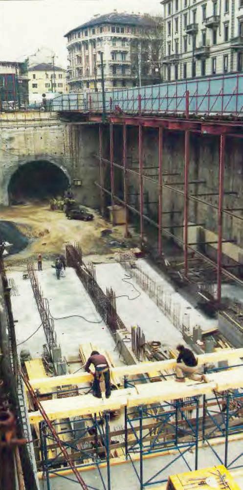
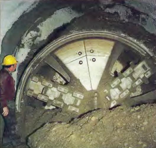
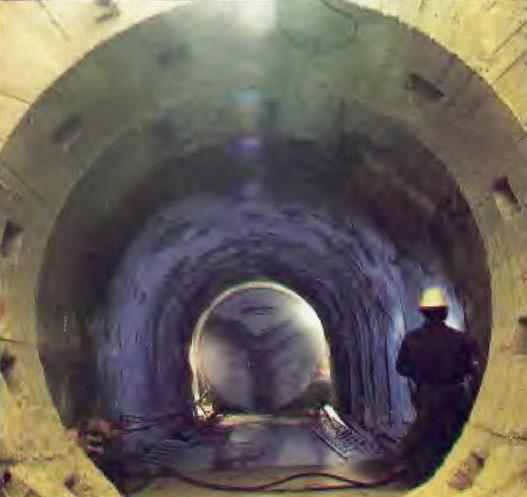
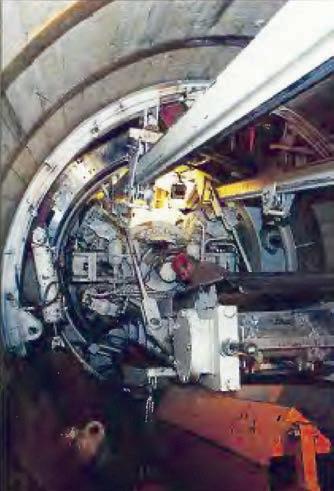
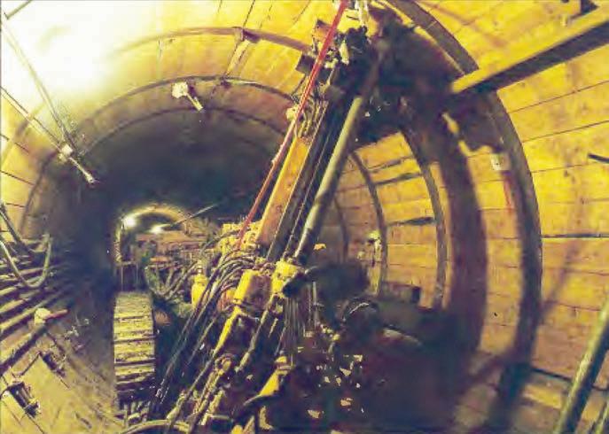
On average, each 1m advance took 50min. As the drive progressed, early ground settlement readings of 18mm were recorded. Further investigation made it clear that it was the cutting principle of the machine causing the trouble.
The teeth on the Lovat cutterhead were proud of the TBM shield resulting in a positive cutting action. That is, the teeth action at the face leaves an open cut into which the loose gravels fall. It would take a substantial increase in thrust and torque to keep the machine's cutterhead hard against the face at all times.
Not wanting to risk further settlement, the TBM was withdrawn after the first 700m drive and the jet grouting concrete pile ring method implemented for the remaining 1,100m. This more-involved technique is largely a grouting operation, and to take charge of it, Rodio was engaged as specialist grouting subcontractor.
With the jet grouting system, an 8.5m long x 5cm diameter grouting lance is inserted and the concrete mixture
injected at 400 atmosphere (4053MN/m2) pressure. Slow rotating withdrawal of the lance ensures a well-formed, full-length pile. From a central batching plant, the cement mixture was pumped along the street, down the shaft and along the tunnel to the face. Once the nine piles are complete, Lodigiani advances the tunnel by about 6.5m with a front-loading excavator which shuttles back and forth to the access shaft. From this shaft, located about midpoint between Lamarmora and Missori Stations, two faces were worked simultaneously. While Rodio installed the piles at one face, Lodigiani advanced the heading in the opposite direction.
The nine piles in fact formed a fluted pattern, each pile on a 10° angle to the horizontal allowing an overlap of approximately 2.5m. Progress with this method is much slower than the TBM drive. It takes 32hr to complete 7m of tunnel from pile formation, through excavation to immediate support shotcreting. But marked improvements in ground settlement have been recorded. Not more than 4mm of settlement has occurred with the jet grouting operation.
For Torno, pilot driving with a 3.3m diameter Bade & Theelen shield supplied by the West German company's Italian agent Tisco of Milan, was more effective. Although advance rates of 10-12m/16hr-day were slower than the Lovat machine, particularly during the relatively longer learning curve for this more complicated piece of machinery, no settlement problems occurred on this drive. Again, the cutting action is significant. The Bade & Theelen shield has a rotating cutterhead with active support panels, which provides a controlled positive cutting action. Slits in the wheel slice the ground rather than dig at it. The cutterhead is also telescopic within the shield. In the dry loose alluvial soils of Milan, it is retracted so that excavation always takes place under the protection of the shield's cutting edge. With this design, 1,500 tonne of forward thrust and a 150 tonne torque was required to keep the cutterhead in constant contact to support the face at all times.
By reversing the face plate arrangement, to have the cutting plates behind the support plates instead of in front of them, the same TBM has a negative action. This is required for excavation of soft water-bearing ground and was first successfully used when a 5.5m diameter shield drove the full profile running tunnels for the Vienna Metro.
Much of Torno's success in Milan, however, was due, to an extent, to an invaluable element of hindsight. Torno did not order its shield until July 1983. By that time, Lodigiani's Lovat was already four months into its drive. The Lovat shield started work in April 1983, ten months before the Bade & Theelen machine started in February 1984. The technical issues with the Lovat shield in this ground were recognised before the Bade & Theelen shield was manufactured and were thus avoided.
Likewise, the successful aspects of the Lovat system were also known. Remembering that there were no contract specifications to follow for the design and operation of a TBM, the diameter of the Bade & Theelen shield is the same as the Lovat shield. Mucking-out was via locodrawn skips and a device on the machine mechanically expanded steel rings between which wood lagging was placed by hand. In effect, Torno and Bade & Theelen used Lodigiani's Lovat as their prototype.
For both contracts, the pilot tunnels proceeded to the original MM specifications. As the pilots advanced, ground consolidation using the tube-a-manchette technique followed close behind. Through 24 tubes inserted on a radial pattern every 1.8m, 270 litres of fine cement grout was injected per 1m3 of ground. Interstices account for some 27% of the ground's volume with permeability of K = 103m/sec. Again, from a central batching plant, grout of 40kg or 60kg cement and 6kg-15kg of dry admixtures was mixed with 150kg of water and pumped at low pressures to the site of application. At this point, it passed through a second pump and was injected at between 12-15 bar pressure. There is one grouting valve every 330mm along the manchette tubes.
With grout injection for this purpose and for jet grouting of the piles, the opposite to ground settlement is as much a danger. Ground movement due to heave must also be just as carefully monitored and restricted to no more than 5mm. Counting the volume needed for consolidation and pile formation, hundreds of litres of grout and cement flowed distances of more than 1,000m along the streets of Milan in pipes encased in low strength concrete for protection.
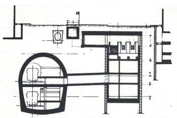
Having completed the pilot tunnels and the associated ground treatment, excavation to the full profile could then begin. Where a double-deck design was needed, the 7.5m wide x 7m high arched top heading is removed first, using a front-loading excavator or roadheader, and supported with steel arches and shotcrete. The reinforced in-situ concrete lining complete with an in-situ concrete invert slab is then cast for the entire length. Following this, the lower 6m wide x 6m high rectangular section of the lower deck will be excavated and in-situ concrete lined to the final 5.8m high x 4.5m wide internal dimensions.
Only seven of the 14 sections on the Yellow Line are being constructed by the tunnelling method. The mezzanine floor of these seven stations, located in available open spaces in the congested city, is excavated by cut-andcover from within 32m deep diaphragm walls (Fig 2).
For both tunnelling contracts, the tunnels were scheduled to be complete by September 1988, ready for a one-year fitting and finishing contract. The line is programmed to be in operation by 1990.
As a total project, the Milan Metro Yellow Line construction works constitute perhaps one of the most important current tunnelling concepts in the world, not only for the lessons learned but also for the long-term implications of TBM application in urban areas. Following the positive performance of the Bade & Theelen shield, the Torno consortium was awarded another pilot tunnel contract from the State Railway Authority using the same machine. This is for the underground rail link between the Garibaldi and Victoria mainline stations. When work started, advance rates of 16m in the two 8hr shifts/day were being achieved.
Caution, however, is still the order of the day. Although MM has since agreed in theory that such a machine could drive two full profile 6.75m diameter tunnels, one on top of the other, such as on the Antwerp Metro, it would be a completely new concept again. MM considered it too much of an unknown quantity in practice to apply it for the first time on such a sensitive project.
But in the words of Erberto Botti, MM's Technical Director for the project, the pilot tunnel experiment on this section of the metro offers encouraging prospects for the future and has uncovered some very important facts in the field of soil mechanics. n
CASE STUDY: Trouble free annular backfilling, highly reliable conveyor mucking, and cutter tools of superior durability helped achieve record breaking TBM advance rates in September 2006 using a Wirth EPBM for twin rail tunnels in Castellanza, near Milan, where the new underground alignment removes the at-grade train line through the town centre.
One of the most frequent and costliest losses of production time on a soft-ground TBM operation is downtime to clear blocked annular grout lines. Another is breakdown of the mucking system, be it derailment of muck trains or a fault trip on a continuous conveyor system. A third major contributor is the replacement of worn cutters, tools, and cutterhead furnishings.
On a tunnel project near Milan, the Strabag/Torno/ Romagnoli JV made decisions about each of these operations that contributed individually to a muchreduced downtime and collectively to impressive production rates. System providers and partners with the JV in this achievement were Häny of Switzerland for a two-component through-the-tailskin annular backfilling system, and TunnelTec of Germany for a continuous conveyor muck hauling system, and rippers, scrapers, and wear-protected cutters hardened with tungsten carbide inserts. Together, they were part of the team that prepared the 8.16m diameter Wirth EPBM to set an Italian record of completing twin 1,850mlong rail tunnels from September 2005 to November 2006.
There is no doubt that through-the-tailskin annular backfilling systems are a significant advance in the control of ground loss and surface settlement in sensitive urban areas. Blockages, however, are frequent, and the smaller diameter tailskin pipes are hard to get at to clean, taking up to five or six hours of downtime to get going again.
Most agree the solution is a two-part backfilling system using a grout mix instead of a mortar, as well as introducing a Part B accelerator as the grout mix leaves the tailskin pipe. Grout for a two-component system comprises only water, cement, and bentonite in suspension with a little stabiliser and retarder and eliminates sand and fillers, the culprits for causing blockages in onepart mortar systems. The water/ cement/bentonite grout also remains inert for at least 72hr or until accelerator is introduced. It then sets quickly to a hard annular fill within 2hr to 4hr. There is no need to clean the pipes between backfilling, or to waste batches of grout because they cannot be used before going off, and if preferred, grout can be batched and pumped from the surface in a continuous flow with the accelerator also fed continuously from a container either on the TBM backup or on the
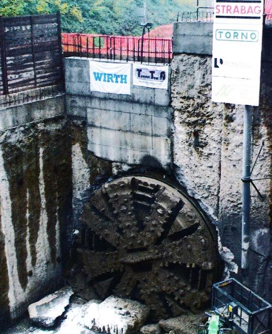
Final breakthrough of the record-setting tunnelling system Portal set-up of the rail tunnel project in Castellanza
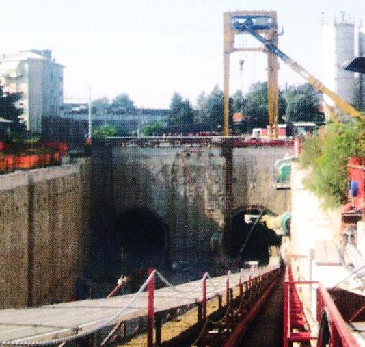
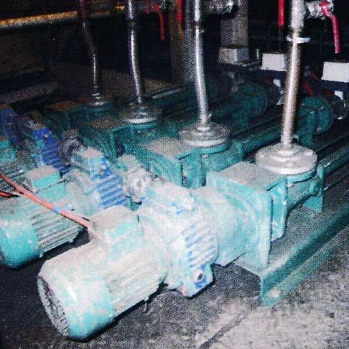
surface. The drawbackis, the two-part method has its own inherent problems, and early efforts to perfect a troublefree system have taken trial and error.
Two-part grouting systems have developed in parallel over recent years in Japan and Europe, with Häny of Switzerland leading the European effort. On the project near Milan, Rudolf Mathis, Equipment and Materials Engineer for Häny, worked with the JV’s Project Manager Salvatore Di Piazza to provide a snarl-free two-part backfill system.
The TBM was one of the two Wirth EPBMs that worked on Contract 240 of the Channel Tunnel Rail Link (CTRL) project in London, UK. The 8.16m o.d. refurbished machine was used by the Strabag/Torno/Romagnoli JV for the twin 1,850m long tunnels, which will replace the railway line through the town of Castellanza. Castellanza is on the main rail route between Malpensa Airport and a main station terminus in Milan. Every ten minutes, traffic comes to a standstill when gates at three level crossings go down for passage of the Malpensa Airport Express and other regional train services. The underground alignment will take the train line out of the middle of town and free up the traffic.
The project called for shallow tunnel drives beneath the existing rail corridor passing close to several buildings and structures, including the abutments of bridges where the line passes under the town’s river. The contract did not specify a particular backfilling system, but with an average 10m of cover through the soft waterbearing alluviums of the local geology, settlement was a major concern. For the JV, selection of the refurbished TBM had the advantage of a tailskin annular-fill system and a Häny plccontrolled annular backfilling system.
What the JV was not aware of, until assembly of the machine, was that the TBM was also equipped with all the elements for a two-component system. For CTRL, the TBM was equipped for a mortar annular-fill system using four Häny ZMP 712V single acting grout pumps to feed four mortar lines. These were later replaced with two Häny ZM 725V double acting pumps to increase the output/ pump and feed only the two upper tailshield mortar lines.
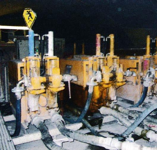
Accelerator dosing equipment was required by the CTRL contractor to provide a quicker setting time of the mortar, if needed, in London.
For the CTRL, Häny drew on the company’s first association with a two-part backfilling system on the Lot F5 high pressure tunnel contract for the Cleuson Dixence hydropower project in Switzerland in 1996. Four Häny accelerator dosing pumps were fitted to the backfilling system of the Lovat TBM that injected mortar through the steel segments of the lining. Mathis was involved on that project for Häny and developed a special adaptor to add accelerator to the mortar line just before the nozzle connection to the segment holes.
“The main problem with conventional one-part backfilling with mortar,” said Mathis, “is the mortar itself. A bad quality mortar mix, poor in either cement or fines, is unstable and can easily plug the lines and the pumps. During longer interruptions, the whole backfilling system has to be cleaned, and any prepared mortar must be wasted.”
“The biggest problem with a two-part back-filling system,” he continued, “is injecting an accurate dose of accelerator at just the right spot to achieve a well-mixed backfill material. The two pumps of the system - the grout or mortar pump and the accelerator dosing pump - must be synchronised perfectly to ensure the correct accelerator to grout or mortar ratio. In addition, the amount of accelerator must automatically adjust to any changes in the volume of grout or mortar being injected. Two-part systems must be carefully managed if they are to succeed.”
Häny’s two-component backfilling system is based on providing each grout line with its own grout pump and dedicated dosing pump. This allows the output and pressure settings of each twinned pair of pumps to be regulated independently to provide the greatest degree of control. Frequency converters fitted to the additive dosing pumps maintain the correct ratio of the Part B component, and a pressure transducer on each line in the tailshield conveys injection data to the central control panel. Dosing pumps working with single acting grout pumps are interconnected with the hydraulic drive of the
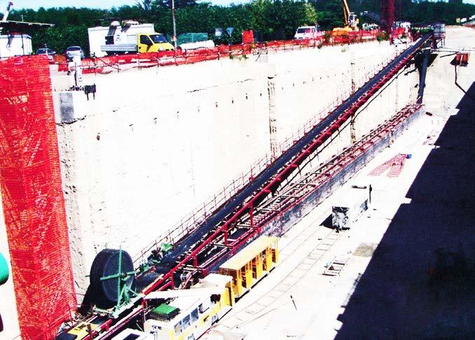
grout pump to permit the dosing of additive during the pumping stroke only.
The output of each grout line can be managed independently of pressure controls and can be programmed, and data recorded by either the stroke-counting method or by more accurate flow meters. Flow and pressure control sensors can also be fitted to the dosing pumps and interconnected with the main control panel. A main control panel at the pumping station on the TBM collects all the data from the flow meters and pressure transducers and transfers the information to the touch screen operating control panel in the TBM operator’s cabin. The panel displays all data and allows alteration of preprogrammed settings as required. On and off pressure limits, impulse values from flow meters or stroke counters, and limits for the time within which pressure should rise above the minimum or switch-on pressure values can be set. An alarm is activated should any of these values be exceeded or any process fail to operate.
For Project Manager Di Piazza, a two component backfill system was specified for the Genoa project he had worked on two years before. The metro tunnels were excavated close to the sea under a high water table. A two-part backfill system that quickly formed a gel and resisted wash-out was needed to control settlement. In Genoa the two-component backfill was injected through the segment grout holes. That was thought easier at the time than developing a two-part through-thetailskin system.
From Genoa, Di Piazza went to a project on the Milan Metro where mortar was used as the one-component backfill. “In that case, it was a big job to clean out everything after a grouting cycle and to be sure to leave nothing in at all,” he said. “Otherwise, the blockages come and there was hell to pay for the time lost for unblocking the pipes and wasting prepared mortar. Problems with the grouting system were always the cause of troubles in the excavation cycle.”
At Castellanza, the JV mobilised for a onepart mortar backfilling operation, but with the TBM set up for a twopart grouting system, Di Piazza was pleased to avoid a
repeat of the Milan experience. He also used his Genoa experience to help guarantee no plugging of the grout lines. Chief among the changes was to extend the additive feed line through the tail shield and beyond the tailseal for mixing of the two components at the outlet of both. In this way, no accelerator stays in the tailshield lines when the pumps stop. Interconnection of the grout pump and additive-dosing pump on the main control panel also ensures that the accelerator pumps stop first, leaving the grout pumps working some seconds longer to remove all two-component grout from the tail pipes. This innovation was a significant contributing factor to the TBM’s high rates of advance.
During the site visit, the TBM was into its second 1,850m long drive. The first was completed on 19 April 2006 after starting in August 2005. Following re-assembly, the TBM started the second drive on 15 July and achieved final breakthrough on 18 November. From 1 September to 5 October, when the TBM entered a shallow purposeexcavated shaft for replacing cutterhead tools, the tunnelling system and its crews completed a record 1,320m, working three 8hr shifts, 7 days/week.
At Castellanza, the annulus between the TBM’s 8.16m diameter and the 7.85m o.d. rings is about 150mm. Grout consumption is approximately 4m3/m of tunnel, and grout is transported into the tunnel in agitator cars from the portal batching plant. With no worries of having to clear the lines between backfilling cycles, the inert water/ cement/bentonite grout can remain in the pipes for days without any fear of plugging.
The original Häny dosing equipment on the TBM was designed for adding a dose of 1.5% to 2% accelerator to a mortar mix. A twocomponent grout-mix backfilling system, however, needs a B component dose of about 7%. Häny replaced the original dosing pumps with ones of higher capacity.
As well as logistical benefits, a twocomponent backfilling system offers savings in labour and materials. Where a onecomponent system requires a team of three or four workers, a two-component system is managed by the TBM operator and one other person who checks the grouting station, responds to alarms, and manages the supply of grout and accelerator, changing over the agicar and containers as they empty and full ones arrive.
In material supplies, the two-part grout system is more economical. The onecomponent mortar mix requires more cement at about 500kg/m3, plus washed sand and a filler of some kind, such as flyash, as well as heavy doses of retarder to extend the life of the mix to about 2hr and a superplasticiser to improve pumpability. A twocomponent grout mix uses less cement at about 300kg/ m3, no sand or filler, and only about 4 litres of retarder and 5 litres of stabiliser to maintain fluidity. It does, however, use more accelerator at about 7%, but accelerator is not an expensive additive. From a long life of up to three days, the grout gels within seconds of introducing the B
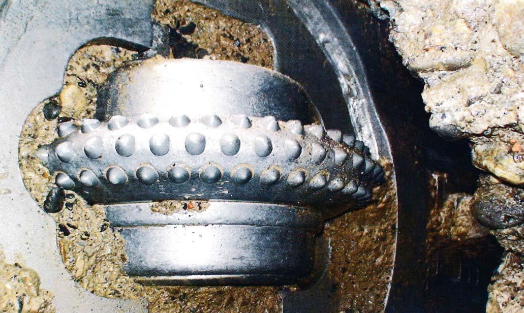
Cutterhead rippers, scrapers, and disc cutters hardened with tungsten carbide inserts
component accelerator. The accelerator at Castellanza is supplied by Sika.
At the grouting station, another advantage of the Häny system was vertical mounting of the grout pumps, which saves on back-up space. By adding a turbo mixer and an agitator, the same equipment can be used for preexcavation stabilisation grouting.
The record-setting achievement at Castellanza was enabled to a large degree by the continuous conveyor system and the cutter tools supplied, installed, and backed-up by TunnelTec of Germany.
Providing that logistics permit, many agree that a continuous conveyor muck hauling system can be significantly more efficient than rail-bound or rubber-tyred muck haulage. At Castellanza, the conveyor system was a modular design and comprised a 800mm-wide, 13mmthick, steel-cord belt powered by two 110kW drive units. With a speed of about 3.3m/sec, the belt had a carrying capacity of 350 tonne/hr.
Through the 1,850m length of each drive, the belt negotiated 600m-radius curves and “worked perfectly” it was said, without causing any muck loss or spillage. Through the 14 months of operation, the belt recorded an availability of more than 99%.
“Another significant part of our supply to the project,” said Stefan Jansen, TunnelTec representative, “was supply of our tools. The geology at Castellanza is very abrasive, and wear was going to be a major issue.” The alluvium deposits comprise largely abrasive sand, gravel, cobbles, and large boulders, some up to 1m in maximum dimension. Combined with the high groundwater table and the shallow cover, cutterhead inspections and tool changes were programmed to take place in shallow, purpose-built temporary shafts
sunk on open space in the rail corridor well ahead of the TBM.
It was following the good experience of using TunnelTec tools and cutters with tungsten carbide bullets or inserts on a previous project that the Castellanza JV decided to dress its TBM with the same tools. Cutterhead tools also included a full set of rippers and scrapers, adecision that proved its worth. Following confidence gained in the performance of the tools on the first drive, the JV set the inspection shaft on the second 1,850m long drive at the 1,300m mark. When on site in early October 2006, the TBM had just passed the inspection shaft and was heading towards the final breakthrough. When the TBM entered the inspection shaft, it was evident that the tungsten carbide hardened tools had performed well. The director of TunnelTec and project manager Di Piazza checked the tools together and “both sides were very satisfied with the result.”
“Through the full 3,700m of tunnel excavation, only 78 rippers and 26 scrapers were replaced,” said Friedhelm Allwicher, Managing Director of TunnelTec. “Tungstencarbide tipped cutters were fitted for only the last 1,850m and didn’t need any replacement. If standard tools had been used, the consumption would have been at least double and would have required several additional inspection shafts to program extra downtime sessions for inspecting and replacing worn tools.”
As technology advances and the improved operation of individual systems are incorporated into the overall performance of a TBM, tunnelling systems will improve to further eliminate avoidable downtime and maximise advance rates. The Castellanza experience is a new milestone on that development trail. The combination of trouble-free annular backfilling, reliable conveyor mucking, and cutter tools of superior durability allowed the machine to achieve 733m of advance in the 30-day month of September. Many a tunnel project around the world aspires to such impressive performance records. n