8 minute read
13 Opening and excavation of the cross-passages

from Tunnelling in the Follo Line Project - NFF Norwegian Tunnelling Society publication no 29
by TunnelTalk

Fabio Moizo, Acciona Ghella Joint Venture (AGJV) Johannes Gollegger, Bane NOR
Cross passages were excavated between the two TBM-tunnels every 480 – 500 meters. The main purpose of this cross passages is for evacuation, but electrotechnical installations are also installed in all the 54 cross passages along the tunnel. Details regarding the evacuation concept is described in chapter 19 “Safety concept for the operational phase”.
Advertisement
Design of the cross passages
The design of the cross passages opening was optimized by 2D and 3D analysis to a uniform width along the tunnel alignment, the final opening width is 3.8m. The design of the opening foresaw some assumptions to be verified during construction.
Among other design loads as weight of the segments, wedge failure and variable loads, the main assumptions for the 3D verification of the segmental lining on the acting water pressure after opening of the TBM segments were the following:
• A residual direct water pressure of 1 bar on the opposite side of the opening and atmospheric pressure on the opening side at ring -1, 0 and +1. • A uniform residual direct water pressure of 1 bar at the boundaries of the 3D model (±5 rings). • A linearly interpolated residual direct water pressure for all other rings of the model. • A uniform indirect water pressure of 3 bar on rings ±3 to ±5. • A uniform indirect water pressure of 3 bar on approximately 190° opposite the Cross Passage opening for rings from -2 to +2. • Atmospheric pressure at the opening and indirect water pressure gradually increasing to 3 bar in rings -1 to +1 • Indirect water pressure linearly interpolated between 0 and 3 bar on the remaining section of the lining.
For final states, an overall non-uniform direct water pressure was applied with a maximum of 11 bars at the opposite side of the opening, with atmospheric pressure on the opening side (see figure 13-2).
Figure 13-1: Water pressure distribution at opening (direct and indirect).

Figure 13-2: Water pressures around the tunnel in final states from hydraulic analyses.
As a result of the 3D model final analysis, the TBM segments at the cross passages (rings -1, 0 and +1) have been designed with additional reinforcement (total of 148.7 kg/m3 compared with a normal 40.7 kg/m3) and 20 kg/m3 of steel fibres B65/35. Special shear connectors between ring -1 and 0 and between ring 0 and +1 have been specified for these segments.

Figure 13-3: Opening design with additional shear connectors.
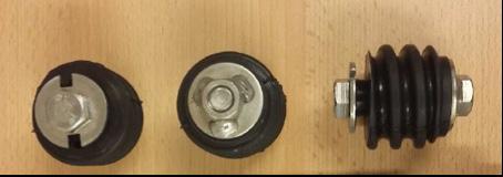
Each cone shear connector can resist to 400kN of shear force.
The design of the openings for the TBM Follobanen cross passages has been focused in avoiding additional unnecessary time consuming works for segment support before the cutting of the latter. The success of the design brought the construction team to significant time saving when starting cross passages excavation works.

Figure 13-4: Shear cone for Cross Passages openings. Figure 13-5: Shear force-displacement curve for Bi-block connectors.

Construction
Before the actual opening of the segments works could start, some measures and mitigations had to be performed: 1. To confirm the design assumptions, pressure measurements were done at ring 0. 2. To avoid lowering of the groundwater table during the excavation works of the cross passage, probe holes and possible pre-grouting works had to be performed. 3. To avoid water running behind the lining, along the tunnel to enter into the cross passage when opening, various grouting activities behind the segmental lining had to be performed in advance.
Pressure measurements
To confirm the design assumptions, manometers were installed in both the opening side and opposite the opening as shown in figure 9a-23. Manometers were normally installed from the back up of the TBM drilling to the rock profile.

Figure 13-6: Manometer locations at ring 0 before opening of Cross Passage.
When the pressure measured in any of the manometers was less than 3bar, no treatment was required. When the pressure in any of the manometer was above the 3bar, post grouting treatment of the rock mass or lowering the pressure behind the segmental lining (both on the opening side and opposite side) was foreseen. When the case of opening the grout ports to lower the pressure behind the segmental lining, ground water level was always monitored through the piezometers system installed from the surface. Lowering of the pressure behind the lining had to be performed in a uniform way (all the grout ports were opened). Water flow was also measured.
Water flow in the rock mass
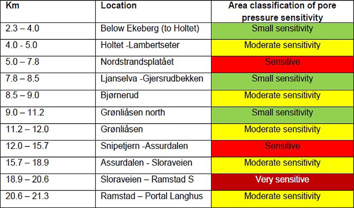
Before the opening of the cross passages and to avoid lowering of the ground water table during excavation and final state (cross passages of the Follobanen project are designed as a drained solution), probe holes had to be drilled in the cross section of the opening. Depending on the location of the cross passage, the water ingress limits were set as shown in table 13-1.

Table 13-1: Limit values for leakage in probe and control hole.
When the measured leakages in the probe holes exceeded the limit values of table 13-1, pre-grouting of the rock mass was performed. Typical drilling pattern of a pre-grouting round from the TBM tunnel can be seen in figure 13-7. Drill holes were drilled before opening of the cross passage. The packers, to allow pre-grouting injections at 40bar were placed 2m from the TBM segmental lining.

Figure 13-7: Drilling pattern for a TBM cross passage pre-grouting round.
Additional probe holes were drilled when possible fracture zones were encountered according to TBM excavation data.
Additional measures before opening of the segment rings
Before cutting of the segments, additional measures were undertaken to limit the water ingress from water running along the tunnel between the segmental lining and the rock mass. These measures can be summarized as:
1. Contact grouting of the backfilling gap from ring -10 to ring +10. 2. Polyurethane (PU) rings at ring -5 and ring +5, with a distance between the holes of 700mm around the cross passage opening. 3. Control holes inside the opening drilled, and water ingress measured. 4. If water ingress exceeded 10 l/min, additional cementitious contact grouting between the PU rings were performed. During the excavation, pre-grouting from the TBMs in the areas where cross passages should be located, was identified to be the most effective method in order to reduce the leakages for the later opening of the cross passages. When this routine was established, pre-excavation grouting from the TBMs were usually performed with two umbrellas on each side of the opening area.
Opening works
The geometry of the opening of the TBM tunnel Cross passage had been reduced to a minimum to avoid additional works to support the TBM segments until the collar was built. The opening is 3.8m width by 4.64 m height.
The TBM tunnel cross passages at the Follo Line project can be subdivided into two categories:
• Cross passages between the TBM tunnels • Cross passages between the TBM tunnels and the escape tunnel
For openings of cross passage between the TBM tunnels, the segments were cut with a diamond saw. Close to the lining, the rock was excavated by using the drill and split methodology. The length of these cross passages were normally approximately

Figure 13-8: Geometry of the TBM tunnel cross passages opening. 25 meters. For excavating the central part of these cross passages, careful blasting, within strict limits, was performed. For the last part of excavation towards the lining of the other tunnel, drill and split were used again. Finally, the lining of the other tunnel was opened by diamond sawing.
As a part of the excavation sequence in the cross passages, probe drilling was performed before the drill and split and before the careful blasting. If leakages from the probe holes exceeded the identified trigger values, pre-grouting was performed to limit the water leakages and avoid drop of the porepressure, lowering of the groundwater table and development of settlements on buildings and structures on the surface. Even though the cross passages were built as drained solutions, mitigations were required in order to limit the leakages and maintain the water balance in the sediments above the tunnel.
The opening of the cross passages between the TBM tunnels and the escape tunnel was characterized by different procedures, depending if the TBM tunnel pipes and TBM tunnel conveyors were on the opening side. When this was the case, and due to safety regulations, a 1st stage opening of 1.7m by 3.8m above the TBM pipes had to be performed.

Figure 13-9: Provisional small opening for escape tunnel cross passages with pipes.
This openings from the escape tunnel were performed with wire cutting technique.

Figure 13-10: Careful blasting, drill and split and finally wire cutting from the escape tunnel.
Figure 13-11: Open cross passage with temporary curtains during the construction phase.
The opening of the cross passages were performed approximately 300 – 500 meter behind the TBMs.